
Owner manual


MAN0855-01-EN Specifications / Installation
__________________________________________________________________________________________________________________________________________________________________
7/22/2009 Page 1 of 4 ECN # 956
1 Specifications
HE-XE102-14 Specifications
Digital DC Inputs
Inputs per Module
12 including 4 configurable HSC
inputs
Commons per Module 1
Input Voltage Range 12 VDC / 24 VDC
Absolute Max. Voltage 35 VDC Max.
Input Impedance
10 kΩ
Input Current Positive Logic Negative Logic
Upper Threshold 0.8 mA -1.6 mA
Lower Threshold 0.3 mA -2.1 mA
Max Upper Threshold 8 VDC
Min Lower Threshold 3 VDC
OFF to ON Response 1 ms
ON to OFF Response 1 ms
HSC Max. Switching Rate
10 kHz Totalizer/Pulse, Edges
5 kHz Frequency/Pulse, Width
2.5 kHz Quadrature
Digital Relay Outputs
Outputs per Module 6 relay
Commons per Module 6
Max. Output Current per Relay 3 A at 250 VAC, resistive
Max. Total Output Current 5 A continuous
Max. Output Voltage 275 VAC , 30 VDC
Max. Switched Power 1250 VA, 150 W
Contact Isolation to XLE
ground
1000 VAC
Max. Voltage Drop at Rated
Current
0.5 V
Expected Life
(See Derating section for
chart.)
No load: 5,000,000
Rated load: 100,000
Max. Switching Rate
300 CPM at no load
20 CPM at rated load
Type Mechanical Contact
Response Time
One update per ladder scan plus
10 ms
Thermistor Inputs, Medium Resolution
Number of Channels 4
Input Ranges
Input Impedance
(Clamped @ -0.5 VDC to 12
VDC)
10K OHMThermistor
Half Bridge
9.59K ohm pulled up to
4.8 VDC
Nominal Resolution
%AI at 10K Ohm
10 Bits
15,008 counts
Conversion Speed
All channels converted once per
ladder scan
Max. Error at 25°C reading /
ambient
±0.5°F or ±0.3°C
Using specified linearization
in ladder program
Filtering
160 Hz hash (noise) filter
1-128 scan digital running average
filter
General Specifications
Required Power
(Steady State)
130 mA @ 24 VDC
Required Power (Inrush) 30 A for 1 ms @ 24 VDC
Primary Power Range 10 – 30 VDC
Relative Humidity 5 to 95% Non-condensing
Operating Temperature
0°C to +50°C
Terminal Type Screw Type, 5 mm Removable
Weight 12 oz. (340.19 g)
CE
UL
See Compliance Table at
http://www.heapg.com/Pages/TechSupport/ProductCert.html
Clock Accuracy +/- 7 Minute/Month at 20C
Highest usable frequency for PWM output is 65 KHz.
2 Panel Cut-Out and Dimensions
Note: Max. panel thickness: 5 mm.
Refer to the XLe/XLt User Manual for panel box information and a handy checklist of requirements.
Note: The tolerance to meet NEMA standards is ± 0.005” (0.1 mm).
3 Ports / Connectors / Cables
Note: The case of the XLe is black, but for clarity, it is shown in a lighter gray color.
XLE OCS Model: HE-XE102-14
12 Digital DC Inputs
4 10k Thermistors
6 Digital Relay Outputs
3
.
6
2
2
[
9
2
m
m
]
3.622 [92mm]
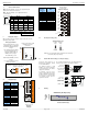
001XLE002
Power Connector
Power Up:
Connect to Earth Ground.
Apply 10 - 30 VDC.
Screen lights up.
Torque rating 4.5 – 7 Lb-In
(0.50 – 0.78 N-m)
CAN Connector
Use the CAN Connector when
using CsCAN network.
Torque Rating 4.5 – 7 Lb-In
(0.50 – 0.78 N-m)
To Remove Back Cover:
Unscrew 4 screws located
on the back of the unit.
Remove cover
.
CAUTION: Do not over
tighten screws when
replacing the back cover.
I/O Jumpers: (Not
Shown):
I/O Jumpers (JP) are
located internally. To
access, remove back cover
of unit.
Wiring Connectors (J1 /
J2):
I/O Jumpers (JP1), and
External Jumpers (RS-
485) are described in the
Wiring and Jumpers
section of this document.
Memory Slot:
Uses Removable Memory
for data logging, screen
captures, program loading
and recipes.
Horner Part No.: HE-MC1
Serial Communications:
MJ1: (RS-232 / RS-485)
Use for Cscape
programming and
Application
-Defined
Communications.
MJ2: (RS-232 / RS-485)
Use for Application-Defined
Communications.
MJ1
(RS-232 / RS-485)
MJ2
(RS-232 / RS-485)
J1
I/O
Jumper
Memory Slot
001XLE029-R2
J2
I/O
Jumper
NET 1
(CsCAN)
Power
DIP
Switch
Note – Your keypad overlay
appearance may differ.
Standard US/EU overlays
pictured here for example
.