
Service Manual
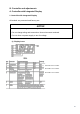
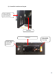
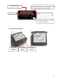
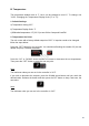
Table Of Contents

13
C. Controller Check
1. Controller
Before replacing Controller that does not show a visible defect and that you suspect is bad,
conduct the following check procedure. This procedure will help you verify your
diagnosis. Always choose a neutral to establish a good neutral connection when
checking high voltages. Also, confirm there is a good power supply and neutral connection
to controller: 115VAC at terminals #6 (Brown) to neutral #7 (White).
Alarm Reset: To silence an alarm, press and release the upper or lower button with power
on. For alarm information, see "III.D.Alarm Safeties".
Startup/Cool Down
1) Check that all wiring connections are properly connected.
2) Move the power switch to the "ON" position.
3) Check for 115VAC at terminals #6 (Brown) to neutral #7 (White). If 115VAC is not present,
check power supply, wiring connections, and power switch continuity.
4) Check that the cabinet temperature is displayed on remote display. If not replace the
controller.
5) Check that Comp icon appears in the display and the Comp and CondFM there is
energized. If not, check CTh status. See "II.D.Thermistor Check". If CTh ohm reading is
in proper range, check for 115VAC at terminals #5 (Black Smooth) to neutral #7 (White). If
115VAC is not present, replace controller.
Defrost
6) Manual Defrost Check: Press and hold the snowflake button until "Snow flake icon"
appears on display.
7) Confirm Comp, CondFM de-energize. The EvapFM must be energized during defrost
time.
8) Check that the components restart after defrost termination.
After 25-min of defrost time, the snowflake icon in the display must turn off, and the Comp
icon must be blinking in the display, 3-min. Comp delay timer starts, after the delay timers
terminate the Comp and CondFM energize.
Legend: Comp-compressor; CondFM-condenser fan motor, EvapFM-Evaporator fan
motor, CTh-cabinet thermistor.