Hoshizaki Hoshizaki America, Inc. Cubelet Icemaker/Dispenser Models DCM-751BAH(-OS) DCM-751BWH(-OS) “A Superior Degree of Reliability” INSTRUCTION MANUAL www.hoshizaki.
IMPORTANT Only qualified service technicians should install, service, and maintain the icemaker. No installation, service, or maintenance should be undertaken until the technician has thoroughly read this Instruction Manual. Likewise, the owner/manager should not proceed to operate the icemaker until the installer has instructed them on its proper operation.
IMPORTANT This manual should be read carefully before the icemaker is installed and operated. Only qualified service technicians should install, service, and maintain the icemaker. Read the warnings contained in this booklet carefully as they give important information regarding safety. Please retain this booklet for any further reference that may be necessary. CONTENTS Important Safety Information.................................................................................................. 4 I.
Important Safety Information Throughout this manual, notices appear to bring your attention to situations which could result in death, serious injury, or damage to the unit. WARNING Indicates a hazardous situation which could result in death or serious injury. CAUTION Indicates a situation which could result in damage to the unit. IMPORTANT Indicates important information about the use and care of the unit.
I. Specifications A. Electrical Data 1. DCM-751BAH (air-cooled) HOSHIZAKI ICE MAKER MODEL NUMBER DCM-751BAH SERIAL NUMBER AC SUPPLY VOLTAGE 115-120/60/1 COMPRESSOR 115V 77LRA 14.6RLA GEAR MOTOR 120V 3.0FLA 1/4HP FAN MOTOR 120V 1.0FLA 50W AGITATING MOTOR 120V 1.8FLA(TOTAL) 110W DISPENSING MOTOR 120V 0.9FLA 55W OTHER 120V 0.6A MAXIMUM FUSE SIZE 20 AMPS MAX. HACR BREAKER (USA ONLY) 20 AMPS MAX. CIRC.
2. DCM-751BAH-OS (air-cooled) HOSHIZAKI ICE MAKER MODEL NUMBER DCM-751BAH-OS SERIAL NUMBER AC SUPPLY VOLTAGE 115-120/60/1 COMPRESSOR 115V 77LRA 14.6RLA GEAR MOTOR 120V 3.0FLA 1/4 HP FAN MOTOR 120V 1.0FLA 50W AGITATING MOTOR 120V 1.8FLA(TOTAL) 110W DISPENSING MOTOR 120V 0.9FLA 55W OTHER 120V 0.6A MAXIMUM FUSE SIZE 20 AMPS MAX. HACR BREAKER (USA ONLY) 20 AMPS MAX. CIRC. BREAKER (CANADA ONLY) 20 AMPS MINIMUM CIRCUIT AMPACITY 20 AMPS DESIGN PRESSURE HI-460PSI LO-290PSI REFRIGERANT 404A 1 LB. 10 OZ.
3. DCM-751BWH (water-cooled) HOSHIZAKI ICE MAKER MODEL NUMBER SERIAL NUMBER AC SUPPLY VOLTAGE COMPRESSOR GEAR MOTOR FAN MOTOR AGITATING MOTOR DISPENSING MOTOR OTHER MAXIMUM FUSE SIZE MAX. HACR BREAKER (USA ONLY) MAX. CIRC. BREAKER (CANADA ONLY) MINIMUM CIRCUIT AMPACITY DESIGN PRESSURE REFRIGERANT DCM-751BWH 115-120/60/1 115V 77LRA 14.6RLA 120V 3.0FLA 1/4HP ---- ---- ---120V 1.8FLA(TOTAL) 110W 120V 0.9FLA 55W 120V 0.6A 20 AMPS 20 AMPS 20 AMPS 20 AMPS HI-460PSI LO-290PSI 404A 1 LB. 6 OZ.
4. DCM-751BWH-OS (water-cooled) HOSHIZAKI ICE MAKER MODEL NUMBER SERIAL NUMBER AC SUPPLY VOLTAGE COMPRESSOR GEAR MOTOR FAN MOTOR AGITATING MOTOR DISPENSING MOTOR OTHER MAXIMUM FUSE SIZE MAX. HACR BREAKER (USA ONLY) MAX. CIRC. BREAKER (CANADA ONLY) MINIMUM CIRCUIT AMPACITY DESIGN PRESSURE REFRIGERANT DCM-751BWH-OS 115-120/60/1 115V 77LRA 14.6RLA 120V 3.0FLA 1/4HP ---- ---- ---120V 1.8FLA(TOTAL) 110W 120V 0.9FLA 55W 120V 0.6A 20 AMPS 20 AMPS 20 AMPS 20 AMPS HI-460PSI LO-290PSI 404A 1 LB. 6 OZ.
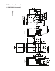
Side View Front View Top View Side View Rear View Unit: mm [in.] B. Dimensions/Connections 1.
Side View Front View Top View Side View Rear View Unit: mm [in.] 2.
Side View Front View Top View Side View Rear View Unit: mm [in.] 3.
Side View Front View Top View Side View Rear View Unit: mm [in.] 4.
II. Installation and Operating Instructions WARNING 1. This icemaker must be installed in accordance with applicable national, state, and local codes and regulations. 2. CHOKING HAZARD: Ensure all components, fasteners, and thumbscrews are securely in place after installation. Make sure that none have fallen into the storage bin. A. Checks Before Installation • Visually inspect the exterior of the shipping container and immediately report any damage to the carrier.
B. How to Remove Panels See Fig. 1 or Fig. 2 • Front Panel: Remove the screw. Lift up and towards you. Disconnect the connector on push-button models. • Top Panel: Lift up at front slightly, push rearward and lift off. • Apron Panel: Remove the screws and pull towards you. Disconnect the connectors on Opti-Serve models. • Side Panels: Remove the screws and pull towards you.
C. Location CAUTION 1. This icemaker is not intended for outdoor use. Normal operating ambient temperature should be within 45°F to 100°F (7°C to 38°C); Normal operating water temperature should be within 45°F to 90°F (7°C to 32°C). Operation of the icemaker, for extended periods, outside of these normal temperature ranges may affect icemaker performance. 2. This icemaker will not work at sub-freezing temperatures.
E. Electrical Connection WARNING 1. Electrical connection must be hard-wired and must meet national, state, and local electrical code requirements. Failure to meet these code requirements could result in death, electric shock, serious injury, fire, or extensive damage to equipment. 2. This unit requires an independent power supply. See the nameplate for proper voltage and breaker/fuse size. Failure to use a proper breaker or fuse can result in a tripped breaker, blown fuses, or damage to existing wiring.
F. Water Supply and Drain Connections See Fig. 4, 5, or 6 WARNING 1. Water supply and drain connections must be installed in accordance with applicable national, state, and local codes and regulations. 2. Normal operating water temperature should be within 45°F to 90°F (7°C to 32°C). Operation of the icemaker, for extended periods, outside of this normal temperature range may affect icemaker performance. 3.
1. Icemaker • Icemaker water supply inlet is 1/2" female pipe thread (FPT). A minimum of 1/4" nominal ID copper water tubing or equivalent is required for the icemaker water supply line. • An icemaker water supply line shut-off valve and drain valve should be installed. • Storage bin and drip tray drain outlets are 3/4" FPT. A minimum of 3/4" nominal ID hard pipe or equivalent is required for the storage bin and drip tray drain lines.
2. Water-Cooled Condenser a) Connection to an Open Drain System • Condenser water supply inlet is 1/2" female pipe thread (FPT). A minimum of 1/4" nominal ID copper water tubing or equivalent is required for the condenser water supply line. • A condenser water supply line shut-off valve and drain valve should be installed. • Condenser drain outlet is 3/8" FPT. A minimum of 1/4" nominal ID hard pipe or equivalent is required for the condenser drain line.
b) Connection to a Closed Loop System • Condenser water supply inlet is 1/2" female pipe thread (FPT). A minimum of 1/4" nominal ID copper water tubing or equivalent is required for the condenser water supply line. • Condenser return outlet is 3/8" FPT. A minimum of 1/4" nominal ID copper water tubing or equivalent is required for the condenser return line. • Shut-off valves and drain valves should be installed at both the condenser water supply inlet and condenser return outlet.
G. Final Checklist WARNING CHOKING HAZARD: Ensure all components, fasteners, and thumbscrews are securely in place after installation. Make sure that none have fallen into the storage bin.
H. Startup WARNING 1. All parts are factory-adjusted. Improper adjustments may adversely affect safety, performance, component life, and warranty coverage. 2. If the icemaker is turned off, wait for at least 3 minutes before restarting the icemaker to prevent damage to the compressor. 3. At startup, confirm that all internal and external connections are free of leaks. 1) Open the water supply line shut-off valve(s). 2) Move the control switch to the "OFF" position. See Fig. 7.
8) Remove the front panel, then remove the storage bin cover. 9) Move the control switch to the "ICE" position. 10) Confirm bin control operation: Remove the control box cover, then engage the safety switch on the front frame. See Fig. 7. After the "GM" LED on the control board turns on, bypass the 5-minute compressor startup delay by pressing the "SERVICE" button. See Fig. 8. WARNING! Risk of electric shock. Care should be taken not to touch live terminals.
III. Cleaning and Maintenance This icemaker must be cleaned and maintained in accordance with the instruction manual and labels provided with the icemaker. Consult with your local distributor about cleaning and maintenance service. To obtain the name and phone number of your local distributor, visit www.hoshizaki.com or call Hoshizaki Technical Support at 1‑800‑233‑1940 in the USA. WARNING 1. Only qualified service technicians should service this icemaker. 2.
A. Cleaning and Sanitizing Instructions Hoshizaki recommends cleaning and sanitizing this unit at least twice a year. More frequent cleaning and sanitizing, however, may be required in some existing water conditions. WARNING 1. To prevent injury to individuals and damage to the icemaker, do not use ammonia type cleaners. 2. Carefully follow any instructions provided with the bottles of cleaning and sanitizing solution. 3.
8) Allow the icemaker to sit for 10 minutes before operation. If you placed a clamp on the reservoir hose in step 6, remove it before operation. 9) In bad or severe water conditions, clean the float switch assembly as described below. Otherwise, continue to step 10. a. Remove the float switch assembly from the reservoir cover. b. Wipe down the float switch assembly with the cleaning solution. c. Rinse the float switch assembly thoroughly with clean water. d.
c) Sanitizing Solution Dilute 0.82 fl. oz. (25 ml) of a 5.25% sodium hypochlorite solution (chlorine bleach) with 1.6 gal. (6.0 l) of warm water. d) Sanitizing Procedure - Following Cleaning Procedure 1) Make sure the control switch is in the "OFF" position, the power supply is off, and the icemaker water supply line shut‑off valve is closed. 2) Remove the front and top panels, then move the power switch to the "OFF" position. 3) Remove the storage bin cover. Remove spout B, then remove spout A.
4) Remove the motor bracket thumbscrews, first from the vertical plane and then from the horizontal plane. While holding on to the corresponding agitator or auger, move the agitating motor or the dispensing motor towards you. Remove the agitators and the dispensing auger from the storage bin. See Fig. 9. 5) Remove the bin control assembly. See Fig. 10. 6) Remove the snap pin, shaft, and actuator. 7) Remove spout B, spout A, and their gaskets.
B. Maintenance The maintenance schedule below is a guideline. More frequent maintenance may be required depending on water quality, the icemaker's environment, and local sanitation regulations. WARNING 1. Only qualified service technicians should service this icemaker. 2. Move the control switch and the power switch to the "OFF" position and turn off the power supply before servicing. Lockout/Tagout to prevent the power supply from being turned back on inadvertently.
C. Preparing the Icemaker for Long Storage CAUTION When storing the icemaker for an extended time or in sub-freezing temperatures, follow the instructions below to prevent damage. When the icemaker is not used for two or three days under normal conditions, it is sufficient to only move the control switch to the "OFF" position. When storing the icemaker for extended time or in sub-freezing temperatures, follow the instructions below. 1.
2. On water-cooled model only, remove the water from the water-cooled condenser: 1) Make sure the control switch and the power switch are in the "OFF" position and that the power supply is off. Remove the top, apron, and left side panels. 2) Close the condenser water supply line shut-off valve. If connected to a closed loop system, also close the condenser return line shut-off valve. 3) Open the condenser water supply line drain valve.
HOSHIZAKI AMERICA, INC. 618 Hwy. 74 S., Peachtree City, GA 30269 USA TEL (770) 487-2331 FAX (770) 487-3360 www.hoshizaki.