
Instruction Manual


17
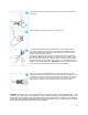
2. Using a pipe wrench, loosen the nut and disconnect the water line at the main
valve, (fig 2).
3. Next, install the “Angle Stop Valve” (C), as shown, (fig 3).
4. Locate the 3/8” flexible tube in the installation kit. Cut a short tube section to
connect the angle stop valve to the other components of the installation kit, (fig 4).
Then install the “ASSE 1032” backflow prevention valve (I), the water pressure
regulator (B) and the shutoff valve (A).
※Install (C), (I) and (B) close to each other. Install (A) close to the DWM-20A on
the countertop. Make sure (C) is installed on the cold water source under the sink,
NOT the hot water source which is often located next to the cold! Insert the other
extremity of the 3/8” tube in the elbow quick-connector in the “WATER INLET” port
located at the back of the DWM-20A. IMPORTANT: open both valves (C) and (A)
so that water from the temporary water line can enter the DWM-20A.
5. TIP: To connect the 3/8” flexible plastic tube to the other components of the
installation kit, simply push the tube into the quick-connect fitting until it stops. Then
pull out the tube to check if it is secured in its position and it is properly connected.
To disconnect it, first push in the collet as shown in the fig 5. Next, with the collet
held in position, remove the tube by pulling it away from the collet as shown.
WARNING: AS DIRECTED IN THE INTERNATIONAL PLUMBING CODE OF THE INTERNATIONAL CODE
COUNCIL AND THE FOOD CODE MANUAL OF THE FOOD AND DRUG ADMINISTRATION (FDA), THIS
DISPENSER MUST BE INSTALLED WITH ADEQUATE BACKFLOW PREVENTION TO COMPLY WITH FEDERAL,
STATE AND LOCAL CODES. FOR MODELS INSTALLED OUTSIDE THE U.S.A., YOU MUST COMPLY WITH THE
APPLICABLE PLUMBING/SANITATION CODE IN YOUR AREA.