Hoshizaki Hoshizaki America, Inc. Modular Flaker Models F-450MAH(-C) “A Superior Degree of Reliability” SERVICE MANUAL www.hoshizaki.
IMPORTANT Only qualified service technicians should install, service, and maintain the icemaker. No service or maintenance should be undertaken until the technician has thoroughly read this Service Manual. Failure to service and maintain the equipment in accordance with this manual may adversely affect safety, performance, component life, and warranty coverage. Hoshizaki provides this manual primarily to assist qualified service technicians in the service and maintenance of the icemaker.
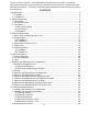
Please review this manual. It should be read carefully before the icemaker is serviced or maintenance operations are performed. Only qualified service technicians should service and maintain the icemaker. This manual should be made available to the technician prior to service or maintenance. CONTENTS I. Specifications .................................................................................................................... 4 1. F-450MAH ...........................................................
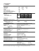
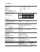
I. Specifications 1. F-450MAH AC SUPPLY VOLTAGE COMPRESSOR GEAR MOTOR FAN MOTOR OTHER MAXIMUM FUSE SIZE MAX. HACR BREAKER (USA ONLY) MAX. CIRC. BREAKER (CANADA ONLY) MINIMUM CIRCUIT AMPACITY APPROXIMATE ICE PRODUCTION PER 24 HR. lbs./day ( kg/day ) Reference without *marks SHAPE OF ICE ICE QUALITY APPROXIMATE STORAGE CAPACITY ELECTRIC & WATER CONSUMPTION ELECTRIC W (kWH/100 lbs.) POTABLE WATER gal./24HR (gal./100 lbs.
2. F-450MAH-C AC SUPPLY VOLTAGE COMPRESSOR GEAR MOTOR FAN MOTOR OTHER MAXIMUM FUSE SIZE MAX. HACR BREAKER (USA ONLY) MAX. CIRC. BREAKER (CANADA ONLY) MINIMUM CIRCUIT AMPACITY APPROXIMATE ICE PRODUCTION PER 24 HR. lbs./day ( kg/day ) Reference without *marks SHAPE OF ICE ICE QUALITY APPROXIMATE STORAGE CAPACITY ELECTRIC & WATER CONSUMPTION ELECTRIC W (kWH/100 lbs.) POTABLE WATER gal./24HR (gal./100 lbs.
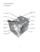
II. General Information 1.
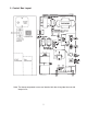
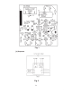
2. Control Box Layout Note: The above component names are identical with the wiring label, but not with the parts list.
3. Timer Board [a] Solid-State Control 1) A HOSHIZAKI exclusive solid-state control is employed in the self-contained flaker icemakers. 2) A printed circuit board (hereafter called “timer board”) includes a stable and high quality control system. 3) All models are pre-tested and factory-adjusted. [b] Timer Board CAUTION 1. Fragile, handle very carefully. 2. A timer board contains CMOS (Complementary Metal-Oxide Semiconductor) integrated circuits, which are susceptible to failure due to static discharge.
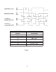
Fig. 1 [c] Sequence Fig.
PART CODE MODEL RATING T1 T2 T3 T4 T5 T6 437305-01 H2AA144C01 24 VAC 50/60Hz 60±15 sec. 90±22 sec. 150±45 sec. 1 sec. or less 6.7 sec. ± 70% 6.7 sec. ± 70% Fig.
Functions of Terminals 1) Terminals 1, 2 Power supply AC 24V. 2) Terminals 3, 4 Control X1 (GM) and X2 (CM) Relays. When closed, energize X1 (GM) in 1 sec. and X2 (CM) in 60 sec. When opened, de-energize X1 (GM) in 150 sec. and X2 (CM) in 90 sec. 3) Terminals 5, 6 Control X1 (GM) and X2 (CM) Relays. When opened, de-energize X1 (GM) and X2 (CM) immediately. When closed again, energize X1 (GM) in 1 sec. and X2 (CM) in 60 sec. 4) Terminals 7, 8, 9 X1 (GM) contacts.
III. Technical Information 1.
2.
[b] F-450MAH-C 14
3. Sequence of Electrical Circuit [a] When power switch is moved to “ON” position and flush switch to “ICE” position, water starts to be supplied to reservoir.
[b] When reservoir has been filled, gear motor starts immediately.
[c] Compressor starts about 60 sec. after gear motor starts.
[d] Bin control operates, and about 6 sec. later, compressor and gear motor stop simultaneously.
[e] Low water (except water-cooled model).
[f] When flush switch is moved to “FLUSH” position, flush water valve opens and flushes reservoir and evaporator.
[g] When flush timer operates (for 21 min. every 12 hours), flush water valve opens and flushes reservoir and evaporator.
[h] When 208-230V are supplied to circuit protect relay, it protects the circuit from being miswired. If the power supply is properly connected, the contact of circuit protect relay does not move even when the coil is energized.
[i] When pressure switch opens, power supply to the control board is cut off causing the compressor and gear motor to turn off immediately.
[j] When input voltage is too low (less than 70%) gear motor fuse (1.5A) is blown causing compressor and gear motor to turn off immediately.
4. Timing Chart Miswiring. Circuit Protect Relay operates. Proper wiring. The unit starts. BIN CONTROL OFF 1. CIRCUIT PROTECT RELAY ON ON OFF UPPER 2. WATER LEVEL UPPER 3. FLOAT SWITCH LOWER 4. WATER CONTROL RELAY 5. CONTROL WATER VALVE 6. FLUSH TIMER 7. FLUSH SWITCH 8. FLUSH WATER VALVE 9. BIN CONTROL LOWER BOTTOM ON OFF ON OFF ON OFF ON OFF 1-2 2-3 FLUSH ICE ON OFF ON OFF 1 sec 10. GEAR MOTOR RELAY 11. GEAR MOTOR 12. FAN MOTOR 6 sec OFF ON OFF ON OFF 60 sec 13.
FLUSH TIMER LOW WATER 1. CIRCUIT PROTECT RELAY ON OFF UPPER 2. WATER LEVEL UPPER 3. FLOAT SWITCH LOWER 4. WATER CONTROL RELAY 5. CONTROL WATER VALVE 6. FLUSH TIMER LOWER BOTTOM ON OFF ON OFF ON OFF ON OFF 1-2 2-3 21 min every 12 hr FLUSH 7. FLUSH SWITCH 8. FLUSH WATER VALVE 9. BIN CONTROL ICE ON OFF ON OFF 150 sec 10. GEAR MOTOR RELAY 11. GEAR MOTOR 12. FAN MOTOR 1 sec 1 sec ON OFF ON OFF ON OFF 90 sec 13. COMPRESSOR 150 sec 60 sec ON OFF 14.
FLUSH SWITCH FLUSH 1. CIRCUIT PROTECT RELAY PRESSURE SWITCH ICE OFF ON ON OFF UPPER 2. WATER LEVEL UPPER 3. FLOAT SWITCH LOWER 4. WATER CONTROL RELAY 5. CONTROL WATER VALVE 6. FLUSH TIMER LOWER BOTTOM ON OFF ON OFF ON OFF ON OFF 1-2 2-3 FLUSH 7. FLUSH SWITCH 8. FLUSH WATER VALVE 9. BIN CONTROL ICE ON OFF ON OFF 150 sec 10. GEAR MOTOR RELAY 11. GEAR MOTOR 12. FAN MOTOR 1 sec ON OFF ON OFF ON OFF 90 sec 13. COMPRESSOR 1 sec 60 sec ON OFF 14.
5. Performance Data [a] F-450MAH APPROXIMATE ICE PRODUCTION PER 24 HR. Ambient 50 Temp. (°F) 70 484 220 80 424 192 90 372 169 lbs./day kg/day 100 327 148 APPROXIMATE ELECTRIC 70 879 -CONSUMPTION 80 896 -90 912 -watts 100 937 -APPROXIMATE WATER 70 0 0 CONSUMPTION PER 24 HR. 80 53 201 90 47 176 gal./day l/day 100 41 155 EVAPORATOR OUTLET TEMP 70 3 -16 80 3 -16 90 7 -14 °F °C 100 9 -13 HEAD PRESSURE 70 225 15.8 80 256 18.0 90 286 20.1 PSIG kg/cm²G 100 324 22.8 SUCTION PRESSURE 70 28 2.0 80 31 2.1 90 33 2.
[b] F-450MAH-C APPROXIMATE ICE PRODUCTION PER 24 HR. Ambient 50 Temp. (°F) 70 430 195 80 380 170 90 135 150 lbs./day kg/day 100 300 135 APPROXIMATE ELECTRIC 70 883 -CONSUMPTION 80 906 -90 928 -watts 100 953 -APPROXIMATE WATER 70 52 195 CONSUMPTION PER 24 HR. 80 46 170 90 16 150 gal./day l/day 100 36 135 EVAPORATOR OUTLET TEMP 70 3 -16 80 3 -16 90 9 -13 °F °C 100 12 -11 HEAD PRESSURE 70 225 15.8 80 257 18.1 90 289 20.3 PSIG kg/cm²G 100 325 22.8 SUCTION PRESSURE 70 28 2 80 31 2.2 90 34 2.
IV. Service Diagnosis 1. No Ice Production PROBLEM [1] The icemaker will not start. [2] Water does not stop, and the icemaker will not start [3] Water has been supplied, but the icemaker will not start. POSSIBLE CAUSE a) Power Supply 1. OFF position. 2. Loose connection. 3. Bad contacts. REMEDY 1. Move to ON position. 2. Tighten. 3. Check for continuity and replace. 4. Blown fuse. 4. Replace. b) Power Switch 1. Off position. 1. Move to ON position. (Control Box) 2. Bad contacts. 2.
PROBLEM POSSIBLE CAUSE c) Gear Motor Relay 1. Coil winding opened. 2. Bad contacts. d) Control Timer (Printed Circuit Board) e) Gear Motor Protect Relay 1. Broken. 1. Coil winding opened. 2. Bad contacts. [4] Water has been a) Gear Motor Fuse supplied. Fan Motor (Bussman GMD starts, but 1.5A) Compressor and b) Thermal Protector Gear Motor will not (Gear Motor) start.
PROBLEM [7] Gear Motor and Compressor start but no ice is produced. POSSIBLE CAUSE a) Refrigerant Line b) Shut-off Valves on Condensing Unit REMEDY 1. Gas leaks. 1. Check for leaks with a leak detector. Reweld leak, replace drier and charge with refrigerant. The amount of refrigerant is marked on Nameplate or Label. 2. Refrigerant line clogged. 1. Closed. 2. Replace the clogged component. 1. Open.
2. Low Ice Production PROBLEM [1] Low ice production POSSIBLE CAUSE a) Refrigerant Line b) High-side Pressure Too High c) Expansion Valve (not adjustable) 1. Gas leaks. REMEDY 1. See "1. [5] a) Refrigerant Line." 2. Replace the clogged component. 3. Recharge. 1. Clean. 2. Refrigerant line clogged. 3. Overcharged. 1. Dirty Air Filter or Condenser. 2. Ambient temperature 2. Get cooler. too warm. 3. Fan rotating too slow. 4. Condensing unit out of order. 1. Low-side pressure too low. 2.
3. Other PROBLEM [1] Abnormal noise POSSIBLE CAUSE a) Fan Motor b) Compressor c) Refrigerant Lines d) Gear Motor (Ice Making) e) Evaporator 1. Bearing worn out. 2. Fan blade deformed. 3. Fan blade does not move freely. 1. Bearings worn out, or cylinder valve broken. 2. Mounting pad out of position. 1. Rub or touch lines or other surfaces. 1. Bearing or Gear worn out / damaged. 1. Low-side pressure too low. 2. [2] Overflow from Reservoir (Water does not stop.
V. Removal and Replacement of Components IMPORTANT 1. The Polyol Ester (POE) oils used in R-404A units can absorb moisture quickly. Therefore it is important to prevent moisture from entering the system when replacing or servicing parts. 2. Always install a new filter drier every time the sealed refrigeration system is opened. 3. Do not leave the system open for longer than 15 minutes when replacing or servicing parts. 1.
6) A liquid charge is recommended for charging an R-404A system. Invert the service cylinder. Open the high-side, service manifold valve. 7) Allow the system to charge with liquid until the pressures balance. 8) If necessary, add any remaining charge to the system through the low-side. Use a throttling valve or liquid dispensing device to add the remaining liquid charge through the low-side access port with the unit running.
3. Removal and Replacement of Compressor IMPORTANT Always install a new drier every time the sealed refrigeration system is opened. Do not replace the drier until after all other repair or replacement has been made. 1) Unplug the icemaker. 2) Remove the panels. 2) Remove the terminal cover on the compressor, and disconnect the compressor wiring. 3) Recover the refrigerant and store it in an approved container, if required by an applicable law.
13) Check for leaks using nitrogen gas (140 PSIG) and soap bubbles. 14) Evacuate the system, and charge it with refrigerant. See the nameplate for the required refrigerant charge and type. 15) Connect the terminals to the compressor, and replace the terminal cover in its correct position. 16) Replace the panels in their correct position. 17) Plug in the icemaker. 4. Removal and Replacement of Drier IMPORTANT Always install a new drier every time the sealed refrigeration system is opened.
5. Removal and Replacement of Expansion Valve IMPORTANT Sometimes moisture in the refrigerant circuit exceeds the drier capacity and freezes up at the expansion valve. Always install a new drier every time the sealed refrigeration system is opened. Do not replace the drier until after all other repairs or replacement have been made. 1) Unplug the icemaker. 2) Remove the panels. 3) Recover the refrigerant and store it in an approved container, if required by an applicable law.
6. Removal and Replacement of Evaporator Assembly 1) Drain the water from the evaporator by switching the flush switch to “FLUSH” on the control box. 2) Unplug the icemaker. 3) Remove the panels. 4) Remove the three thumbscrews and take off the spout from the evaporator. Cutter 5) Loosen the cutter by a wrench and remove it. 6) Remove the cylinder gasket at the top of the evaporator. Extruding Head 7) Remove the three socket head cap screws and lift off the extruding head.
11) Remove the bulb of the expansion valve. 12) Disconnect the brazing-connections of the expansion valve and the copper tubelow side from the evaporator, using brazing equipment. 13) Remove the two truss head machine screws and the bracket securing the evaporator. 14) Disconnect the three hoses from the evaporator. 15) Remove the four socket head cap screws securing the evaporator with the bearing-lower. 16) Lift off the evaporator.
23) When replacing the evaporator: (a) Braze the new evaporator with nitrogen gas flowing at the pressure of 3-4 PSIG. (b) Replace the drier. (c) Check for leaks using nitrogen gas (140 PSIG) and soap bubbles. (d) Evacuate the system. Charge it with refrigerant. See the nameplate for required refrigerant charge and type. 24) Replace the panels in their correct position. 25) Plug in the icemaker. 7. Removal and Replacement of Fan Motor 1) Unplug the icemaker. 2) Remove the panels.
6) Remove the water supply hose from the control water valve. 7) Install the new control water valve. 8) Assemble the removed parts in the reverse order of the above procedure. 9) Open the water supply line shut-off valve. 10) Check for water leaks. 11) Replace the panels in their correct position. 12) Plug in the icemaker. 9. Removal and Replacement of Flush Water Valve 1) Turn off the power supply. 2) Remove the panels. 3) Close the water supply line shut-off valve.
14) Move the flush switch to the “ICE” position. 15) Check for water leaks. 16) Move the flush switch to the “FLUSH” position, and make sure water is flushing. 17) Move the flush switch to the “ICE” position. 18) Replace the panels in their correct position. VI. Cleaning and Maintenance IMPORTANT Ensure all components, fasteners and thumbscrews are securely in place after any maintenance or cleaning is done to the equipment. 1.
9) Replace the front panel in its correct position. 10) Close the drain valve. 11) Remove all ice from the storage bin, and clean the bin. 2. Cleaning and Sanitizing Instructions WARNING 1. HOSHIZAKI recommends cleaning this unit at least once a year. More frequent cleaning, however, may be required in some existing water conditions. 2. To prevent injury to individuals and damage to the icemaker, do not use ammonia type cleaners. 3.
[b] Cleaning Procedure The cleaning process will remove lime deposits from the water system. 1) Remove the front panel and top panel, then turn off the power supply. 2) Close the water supply line shut-off valve. 3) Remove all ice from the storage bin. 4) Move the flush switch to the “FLUSH” position. 5) Turn on the power supply and drain out all water from the water line. 6) Turn off the power supply. 7) Remove the strap connecting the spout to the chute assembly.
[c] Sanitizing Solution Dilute 2.5 fl. oz. (74 ml or 5 tbs) of IMS-II Sanitizer or a 5.25% sodium hypochlorite solution (chlorine bleach) with 5 gallons (19 l) of warm water. IMPORTANT For safety and maximum effectiveness, use the solution immediately after dilution. [d] Sanitizing Procedure - Initial The sanitizing process will sanitize the icemaker. 1) Close the water supply line shut-off valve. 2) Remove the strap connecting the spout to the chute assembly.
14) Replace all parts in their correct positions. IMPORTANT When installing the baffles, make sure that the bent surface (the one without the studs) faces the actuator so that the bent surface can guide the ice to the center of the actuator. 15) Move the flush switch to the “ICE” position, then turn on the power supply. Replace the top panel and front panel in their correct positions. Make ice using the solution until the icemaker stops making ice.
16) When the gear motor starts, remove the front panel and turn off the power supply. 17) Drain out all water from the water line. See 2) and 3). 18) Move the flush switch to the “ICE” position and run the icemaker. 19) Turn off the power supply after 30 minutes. 20) Pour warm water into the storage bin to melt all ice, and then clean the bin liner with the solution. 21) Flush out any solution from the storage bin. 22) Turn on the power supply and start the automatic icemaking process. IMPORTANT 1.
3. Maintenance Instructions IMPORTANT 1. This icemaker must be maintained individually, referring to the instruction manual and labels provided with the icemaker. 2. To have the optimum performance of this icemaker, the following consumable parts need periodic inspection, maintenance and replacement: Extruding Head Housing Gear Motor Auger Mechanical Seal These parts should be inspected at least once a year or every 10,000 hours of operation.
3) Air Filter A plastic mesh air filter removes dirt or dust from the air, and keeps the condenser from getting clogged. As the filter gets clogged, the icemaker’s performance will be reduced. Check the filter at least twice a month. When clogged, use warm water and a neutral cleaner to wash the filter. 4) Condenser Check the condenser once a year, and clean if required by using a brush or vacuum cleaner. More frequent cleaning may be required depending on the location of the icemaker.