Hoshizaki Hoshizaki America, Inc. Modular Flaker Models FD-1001MAH(-C) FD-1001MWH(-C) FD-1001MRH(-C) FD-1001MLH(-C) “A Superior Degree of Reliability” SERVICE MANUAL www.hoshizaki.
IMPORTANT Only qualified service technicians should install, service, and maintain the icemaker. No service or maintenance should be undertaken until the technician has thoroughly read this Service Manual. Failure to service and maintain the equipment in accordance with this manual may adversely affect safety, performance, component life, and warranty coverage. Hoshizaki provides this manual primarily to assist qualified service technicians in the service and maintenance of the icemaker.
IMPORTANT This manual should be read carefully before the icemaker is serviced or maintenance operations are performed. Only qualified service technicians should install, service, and maintain the icemaker. Read the warnings contained in this booklet carefully as they give important information regarding safety. Please retain this booklet for any further reference that may be necessary. CONTENTS Important Safety Information....................................................................................
3. Alarm Safeties........................................................................................................ 30 a) Low Water Safety (1-beep alarm)..................................................................... 30 b) Control Switch in the "DRAIN" Position (2-beep alarm).................................... 30 c) High Pressure Switch (3 & 4-beep alarms)....................................................... 30 d) Freeze Timer (5-beep alarm)....................................................
IV. Service Diagnosis........................................................................................................... 58 A. Ice Production Check................................................................................................... 58 B. Diagnostic Procedure.................................................................................................. 58 C. Control Board Check................................................................................................... 61 D.
VI. Cleaning and Maintenance............................................................................................. 96 A. Cleaning and Sanitizing Instructions............................................................................ 96 1. Cleaning Solution................................................................................................... 96 2. Cleaning Procedure................................................................................................ 96 3. Sanitizing Solution..
Important Safety Information Throughout this manual, notices appear to bring your attention to situations which could result in death, serious injury, or damage to the unit. WARNING Indicates a hazardous situation which could result in death or serious injury. CAUTION Indicates a situation which could result in damage to the unit. IMPORTANT Indicates important information about the use and care of the unit.
I. Specifications A. Icemaker 1. FD-1001MAH (air-cooled) Awaiting Data Note: We reserve the right to make changes in specifications and design without prior notice.
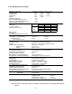
2. FD-1001MAH-C (air-cooled) AC SUPPLY VOLTAGE COMPRESSOR GEAR MOTOR FAN MOTOR OTHER MAXIMUM FUSE SIZE MAX. HACR BREAKER (USA ONLY) MAX. CIRC. BREAKER (CANADA ONLY) MINIMUM CIRCUIT AMPACITY APPROXIMATE ICE PRODUCTION PER 24 HR. lbs./day ( kg/day ) Reference without *marks SHAPE OF ICE ICE QUALITY APPROXIMATE STORAGE CAPACITY ELECTRIC & WATER CONSUMPTION ELECTRIC W (kWH/100 lbs.) POTABLE WATER gal./24HR (gal./100 lbs.
3. FD-1001MWH (water-cooled) Awaiting Data Note: We reserve the right to make changes in specifications and design without prior notice.
4. FD-1001MWH-C (water-cooled) Awaiting Data Note: We reserve the right to make changes in specifications and design without prior notice.
5. FD-1001MRH (remote air-cooled) Awaiting Data Note: We reserve the right to make changes in specifications and design without prior notice.
6. FD-1001MRH-C (remote air-cooled) AC SUPPLY VOLTAGE COMPRESSOR GEAR MOTOR FAN MOTOR REMOTE OTHER MAXIMUM FUSE SIZE MAX. HACR BREAKER (USA ONLY) MAX. CIRC. BREAKER (CANADA ONLY) MINIMUM CIRCUIT AMPACITY APPROXIMATE ICE PRODUCTION PER 24 HR. lbs./day ( kg/day ) Reference without *marks SHAPE OF ICE ICE QUALITY APPROXIMATE STORAGE CAPACITY ELECTRIC & WATER CONSUMPTION ELECTRIC W (kWH/100 lbs.) POTABLE WATER gal./24HR (gal./100 lbs.
7. FD-1001MLH (low side, parallel rack system) Awaiting Data Note: We reserve the right to make changes in specifications and design without prior notice.
8. FD-1001MLH-C (low side, parallel rack system) Awaiting Data Note: We reserve the right to make changes in specifications and design without prior notice.
B. Condenser Unit 1. URC-5F a) Specifications AC SUPPLY VOLTAGE 115/60/1 (Connection to Icemaker) FAN MOTOR 115 V EXTERIOR DIMENSIONS (WxDxH) 21-15/16" x 15-11/16" x 17-7/8" (557 x 398 x 454 mm) DIMENSIONS INCLUDING LEGS (WxDxH) 24" x 18-1/8" x 32-13/16" (610 x 460 x 834 mm) EXTERIOR FINISH Galvanized Steel WEIGHT Net 61 lbs. ( 28 kg ) CONNECTIONS - ELECTRIC Permanent - Connection - REFRIGERANT Total 1.3FLA 65W Shipping 68 lbs.
b) Dimensions 24" (610 mm) 15-11/16" (398 mm) 14-1/8" (358 mm) 14-9/16" (370 mm) 17-1/8" (435 mm) 6/16" × 3/4" (10×20 mm) 4×2 (SLOTTED HOLES) 18-1/8" (460 mm) 20-15/32" (520 mm) 2-1/2" (63 mm) 17-7/8" (454 mm) 21-15/16" (557 mm) 14-15/16" (380 mm) 18-1/8" (460 mm) 19-11/16" (500 mm) 14-15/16" (380 mm) Unit: in. (mm) 23-1/32" (585 mm) 7/8" DIA. HOLE (23 mm DIA.
II. General Information A. Construction 1.
2.
3.
4.
5.
B. Sequence of Operation The steps in the sequence are as outlined below. This unit utilizes a control board to switch the components on and off as needed. When power is supplied, the power switch is in the "ON" position, and the control switch is in the "ICE" position, CB "POWER OK" LED comes on. 1. Sequence Cycles and Shutdown a) Fill Cycle "WTRIN" LED is on. WV energizes and fill cycle begins. UF/S closes and WV de‑energizes. 30-second GM delay timer starts.
(3) Manual Drain: Manual drain is used when servicing evaporator components and cleaning and sanitizing the unit. When the unit is making ice and the control switch is moved to the "DRAIN" position, there is a 3-second delay, then CR (X1 on CB) and Comp (LLV and SLV on MLH models) de‑energize and the 5-minute ice purge timer begins. When the 5-minute ice purge timer terminates, GMR (X2 on CB), GM, GMPR, and FM/FMR de-energize. DV energizes to drain the evaporator and reservoir.
Maximum 90 seconds 1. Fill Cycle 25 Legend: Comp-compressor CR-compressor relay DC-drain cycle DT-drain timer DV-drain valve FM-fan motor FMR-fan motor-remote FT-fill timer (low water safety) GM-gear motor GMPR-gear motor protect relay (S1 dip switch 4) 3.
C. Control Board • A Hoshizaki exclusive control board is employed in FD-1001MAH(-C), FD‑1001MWH(-C), FD-1001MRH(-C), and FD-1001MLH(-C) Modular Flakers. • All models are pre-tested and factory set. CAUTION 1. The control board is fragile; handle very carefully. 2. The control board contains integrated circuits, which are susceptible to failure due to static discharge. It is especially important to touch the metal part of the icemaker before handling or replacing the control board. 3.
1.
2. Features a) Low Water Safety When the inlet water valve opens during fill and refill, a 90-second low water safety timer starts. Once the upper float switch closes the 90-second low water safety timer terminates. If the upper float switch remains open longer than 90 seconds, a 1-beep alarm sounds. The water valve and 1-beep alarm continue until the upper float switch closes.
f) High Voltage and Low Voltage Cut-outs The maximum and minimum allowable supply voltages of this icemaker are limited by the high voltage (147Vac±5% or more) and low voltage (92Vac±5% or less) cut-outs. When high voltage (147Vac±5% or more) is present, the icemaker automatically stops and the control board signals with a 7-beep alarm every 3 seconds. When low voltage (92Vac±5% or less) is present, the icemaker automatically stops and the control board signals with a 6-beep alarm every 3 seconds.
3. Alarm Safeties a) Low Water Safety (1-beep alarm) (1) Fill Cycle: If upper float switch remains open 90 seconds after the inlet water valve has energized, the control board sounds a 1-beep alarm every 5 seconds. The alarm resets and the icemaker automatically starts running again once water is restored or the float switch is cleaned or replaced.
f) High Voltage (7-beep alarm) The maximum allowable supply voltage for this icemaker is limited by the high voltage cut‑out. When high voltage (147.5Vac ±5% or more) is present, the "POWER OK" LED turns off and the control board shuts down the unit and sounds a 7-beep alarm every 5 seconds. When the proper supply voltage resumes, the unit automatically starts running again. g) Gear Motor (8-beep alarm) Gear motor operation is confirmed through the gear motor protect relay (control board K1 connector).
b) Infrared Sensor Shutdown Delay (S1 dip switch 1, 2, & 3) Infrared sensor shutdown delay is the delay between the infrared sensor detecting ice (yellow LED flashing or steady) and the start of the shutdown sequence. For dispenser unit applications, the ice level at shutoff may need to be adjusted depending on the dispenser agitation or dispense method. Increasing the shutdown delay setting allows for a higher level of ice in the bin before the icemaker shuts down.
e) Bin Control Selector (S1 dip switch 7) This unit is factory set for infrared sensor bin control operation. No adjustment is required. When used on a standard ice storage bin, the mechanical bin control may be used instead of the infrared sensor by moving S1 dip switch 7 to the off position. In the factory default position (S1 dip switch 7 in the on position), the gear motor delay after the upper float switch closes is 30 seconds.
D. Bin Control An infrared sensor is used to control the level of ice in the dispenser unit/ice storage bin (S1 dip switch 7 in the "ON" position). The infrared sensor is the primary bin control device. 20VDC powers the infrared sensor from the control board K6 connector. A green power LED and a yellow ice detection LED are located on the infrared sensor. See Fig. 1. The paddle‑actuated mechanical bin control is used as a backup bin control and safety device. See Fig. 2. For further details, see "IV.D.
III. Technical Information A. Water Circuit and Refrigeration Circuit 1.
2. FD-1001MWH(-C) (water-cooled) Inlet Water Valve Spout Float Switch Water Supply Line Insulation Water Level Reservoir Evaporator Expansion Valve Overflow Gear Motor Drain Valve Drain Outlet Drain Pan Drier Pressure Switch Cond. Water Inlet Cond.
3.
4.
B. Wiring Diagrams 1.
2.
3. Sequence Wiring Diagram a) Fill Cycle. Power supply is turned on. Inlet water valve energizes and reservoir fills.
b) Ice Purge Cycle Upper float switch closes, 30-second gear motor delay timer starts. After 30-second gear motor delay timer terminates, 5-minute ice purge timer starts, gear motor, fan motor/ fan motor-remote energize. Note: The 30-second gear motor delay is active when S1 dip switch 7 is in the on position. Otherwise, gear motor has a 5-second delay when upper float switch closes.
c) Freeze Cycle 5-minute ice purge timer terminates, compressor energizes (liquid line valve, and suction line valve on MLH models).
d) 1-in-1 Drain Cycle Compressor, (liquid line valve, suction line valve on MLH models), fan motor/fan motor‑remote, and gear motor continue. Drain valve energizes for 2 seconds every hour.
e) 1-in-12 Drain Cycle 1-in-12 drain cycle initiates (S1 dip switch 4). Compressor and fan motor/fan motor‑remote de-energize. 5-minute ice purge timer starts and gear motor continues. 5‑minute ice purge timer terminates, gear motor de-energizes. Drain valve opens for 10 minutes.
f) Infrared Sensor Shutdown Ice fills storage bin to level of activating infrared sensor, infrared sensor yellow LED turns on (flashing or steady). Infrared sensor shutdown sequence begins. For further information, see "II.B.1.e) Shutdown Cycle.
g) Mechanical Bin Control Shutdown Ice fills the chute to the point of engaging the mechanical bin control. Dip Switch 7 "ON": The icemaker shuts down within 10 seconds of the mechanical bin control opening and a 9-beep alarm sounds. Dip Switch 7 "OFF": Hoshizaki ice storage bin applications only. The icemaker shuts down within 10 seconds of the mechanical bin control opening.
h) Low Water Safety During fill or refill, should the upper float switch fail to close within 90 seconds after the water valve energizes, a 1-beep alarm sounds. The water valve remains open until the upper float switch closes. If this occurs during refill, the icemaker cycles down.
i) High Pressure Switch If pressure on the refrigeration circuit high-side exceeds Hoshizaki specifications, a high pressure switch activates. The control board then shuts down the unit until the high-side pressure returns to an acceptable level. See "II.C.3.c) High Pressure Switch (3 & 4-beep alarms).
C. Performance Data 1. FD-1001MAH (air-cooled) Awaiting Data Note: We reserve the right to make changes in specifications and design without prior notice.
2. FD-1001MAH-C (air-cooled) APPROXIMATE ICE PRODUCTION PER 24 HR. lbs./day (kg/day) APPROXIMATE ELECTRIC CONSUMPTION watts APPROXIMATE WATER CONSUMPTION PER 24 HR. gal./day (l/day) EVAPORATOR OUTLET TEMP. °F (°C) HEAD PRESSURE PSIG (kg/cm²G) SUCTION PRESSURE PSIG ( kg/cm²G ) TOTAL HEAT OF REJECTION Ambient Temp. (°F) 70 80 90 100 70 80 90 100 70 80 90 100 70 80 90 100 70 80 90 100 70 80 90 100 Water Temp.
3. FD-1001MWH (water-cooled) Awaiting Data Note: We reserve the right in make changes to specifications and design without prior notice.
4. FD-1001MWH-C (water-cooled) Awaiting Data Note: We reserve the right to make changes in specifications and design without prior notice.
5. FD-1001MRH (remote air-cooled) Awaiting Data Note: We reserve the right to make changes in specifications and design without prior notice.
6. FD-1001MRH-C (remote air-cooled) APPROXIMATE ICE PRODUCTION PER 24 HR. lbs./day (kg/day) APPROXIMATE ELECTRIC CONSUMPTION watts APPROXIMATE WATER CONSUMPTION PER 24 HR. gal./day (l/day) EVAPORATOR OUTLET TEMP. °F (°C) HEAD PRESSURE Ambient Temp. (°F) 70 80 90 100 70 80 90 100 70 80 90 100 70 80 90 50 *930 *(423) 825 (375) (332) 730 (294) 645 *1401 -1422 -1442 -1440 -*112 *(423) (375) 99 (332) 88 (294) 78 *5 *(-15) 5 (-15) (-13) 9 Water Temp.
7. FD-1001MLH (low side, parallel rack system) Awaiting Data Note: We reserve the right to make changes in specifications and design without prior notice.
8. FD-1001MLH-C (low side, parallel rack system) Awaiting Data Note: We reserve the right to make changes in specifications and design without prior notice.
IV. Service Diagnosis WARNING 1. This unit should be diagnosed and repaired only by qualified service personnel to reduce the risk of death, electric shock, serious injury, or fire. 2. Risk of electric shock. Use extreme caution and exercise safe electrical practices. 3. Moving parts (e.g., fan blade) can crush and cut. Keep hands clear. 4. CHOKING HAZARD: Ensure all components, fasteners, and thumbscrews are securely in place after the unit is serviced.
5) Turn on the power supply, then move the power switch to the "ON" position. Make sure the control switch is in the "ICE" position. CB "POWER OK" LED and IS green LED turn on. Diagnosis "POWER OK" LED: Check that CB "POWER OK" LED is on. If not, check for proper supply voltage (115VAC) input to the control transformer. If 115VAC is not present, check the power switch and breaker. Next, check that the circuit protect relay is de-energized (closed between terminals #1 and #5).
7) Ice Purge Cycle – "GM" LED is on. 30-second GM delay timer and 30‑minute freeze timer start. WV de-energizes and "WTRIN" LED turns off. Once the 30‑second GM delay timer terminates, the 5-minute ice purge timer starts. GMR (X2 on CB), GM, GMPR, FM/FMR, and EHH (‑C model only) energize. Diagnosis: If "GM" LED is off, check that WV de‑energizes and UF/S closes. If "GM" LED is on and GM is off, confirm 115VAC at CB K1 connector pin #3 black (BK) to white (W) neutral.
10) Shutdown – See "IV.D. Bin Control Check." Legend: CB–control board; Comp–compressor; DV–drain valve; EHH–extruding head heater (-C model only); FM–fan motor; FMR–fan motor-remote; GM–gear motor; GMPR–gear motor protect relay; GMR–gear motor relay; IS–infrared sensor; LF/S–lower float switch; LLV–liquid line valve (MLH model only); MBC–mechanical bin control; SLV–suction line valve (MLH model only); UF/S–upper float switch; WV–inlet water valve C.
4) Infrared Sensor (K6 connector): Check that the infrared sensor green LED is on. If not, check for 20VDC from the black K6 connector dark blue wire (DBU) to the K6 connector brown (BR) wire. See Fig. 4. If 20VDC is not present, the control board is bad and must be replaced. Next, confirm that the yellow LED is not flashing or steady. If IS yellow LED is on or flashing, move ice away from IS lens. If no ice is present, clean the lens with a warm, clean damp cloth.
a. Control Switch (K9 connector pins #1 and #2 white/black (W/BK) wires): 5VDC is present from the white K5 connector pin closest to red K4 connector to the K9 connector pin #1 white/black (W/BK) wire at all times. If 5VDC is not present, the control board is bad and must be replaced. When the control switch is in the "ICE" position, the control switch contacts are open. 0VDC is present from the white K5 connector pin closest to red K4 connector to the K9 connector pin #2 white/black (W/BK) wire.
e. Float Switch (K8 connector pins #5 black (BK) wire, #6 red (R) wire (upper), and #7 dark blue (DBU) wire (lower)): 5VDC is present from the white K5 connector pin closest to red K4 connector to the K8 connector pin #5 (black (BK) wire). If 5VDC is not present, the control board is bad and must be replaced. For further float switch diagnostics, see "IV.E. Float Switch Check and Cleaning.
Control Switch #1 to #2 (white/black) "ICE"-Open-5VDC "DRAIN"-Closed-0VDC High Pressure Switch #3 to #4 (yellow) Open-5VDC Closed-0VDC Gear Motor Protect Relay Circuit #5 to #6 (white/orange) Relay De-Energized-Open-5VDC Relay Energized-Closed-0VDC • K9 Connector • "SERVICE" Button (Ice Purge Cycle Bypass) • K8 Connector (24VAC and 5VDC) • K1 Connector (115VAC) #3 Input (black) #2 GM, FMR, FMS (brown) Transformer 24VAC Input #1 (white/red) Transformer 24VAC Neutral #2 (light blue) • K2 Connector Me
D. Bin Control Check 1. Infrared Sensor Check IMPORTANT Make sure S1 dip switch 7 is in the "ON" position. This allows the control board to monitor the infrared sensor along with the mechanical bin control. 1) Turn off the power supply. 2) Remove the front panel, top panel, and control box cover. 3) Confirm that S1 dip switch 1, 2, & 3 are in the proper position for your application. See "II.C.4.b) Infrared Sensor Shutdown Delay (S1 dip switch 1, 2, & 3).
9) Remove the object covering the infrared sensor. If you removed the infrared sensor housing from the base, replace it in its correct position, and secure it with the thumbscrew. 10) Move the power switch to the "OFF" position. Turn off the power supply, then proceed to "IV.D.2. Mechanical Bin Control Check." Infrared Sensor LED Infrared Sensor Thumbscrew Infrared Sensor LED Infrared Sensor Housing Fig. 7 Lens 2.
5) Make sure the "GM" LED is on. There is a delay of at least 30 seconds before the "GM" LED turns on after power‑up. After the "GM" LED turns on, press the "SERVICE" button on the control board to bypass the 5-minute compressor delay. WARNING! Risk of electric shock. Care should be taken not to touch live terminals. The "COMP" LED turns on. 6) Press the actuator paddle located in the top of the chute.
E. Float Switch Check and Cleaning 1. Float Switch Check 1) Remove the front panel and move the power switch to the "OFF" position. Move the control switch to the "DRAIN" position. 2) Move the power switch to the "ON" position. 3) Allow the water to drain from the reservoir, then move the power switch to the "OFF" position and the control switch to the "ICE" position. 4) Remove the molex plug from the control box and check continuity across the float switch wires.
Red (R) (upper float switch) Black (BK) (common) Dark Blue (DBU) (lower float switch) Magnet (towards top) Upper Float (blue) Spring Retainer Clip Magnet (towards top) Lower Float (white) Plastic Retainer Clip Fig. 9 Float Switch Assembly Reservoir Cover Reservoir Fig.
F. Diagnostic Charts 1. No Ice Production Problem Possible Cause [1] The icemaker will not a) Power Supply start. Remedy 1. Off, blown fuse, or tripped breaker. 1. Turn on, replace, or reset. 2. Loose connection. 2. Tighten. 3. Bad contacts. 3. Check for continuity and replace. 4. Not within specifications. 4. Refer to nameplate and correct. b) Water Supply 1. Water supply off or pressure too low. 1. Check and get recommended pressure. c) Power Switch (Control Box) 1. "OFF" position. 1.
Problem Possible Cause Remedy 7. Check and get [1] The icemaker will not i) High Pressure Switch 7. Condenser water (continued) pressure too low or off recommended pressure. start (continued). (water-cooled model). 8. Water regulating 8. Adjust it lower. valve set too high (water‑cooled model). j) Control Switch [2] Fill cycle will not terminate. [3] Ice purge cycle will not start. 1. "DRAIN" position. 1. Move to "ICE" position. 2. Bad contacts. 2. Check for continuity and replace.
Problem [4] Freeze cycle will not start (compressor) (continued). Possible Cause d) Compressor Remedy 1. Wiring to compressor. 1. Check for loose or open connection, repair or replace. 2. Loose connections. 2. Tighten. 3. Motor winding opened 3. Replace. or grounded. [5] Freeze cycle starts, but no ice is produced. 4. Compressor locked and motor protector tripped. 4. Replace. e) Power Supply 1. Not within specifications. 1. Refer to nameplate and correct. a) Refrigerant Line 1. Gas leaks. 1.
2. Low Ice Production Problem [1] Low ice production. Possible Cause Remedy a)Evaporator 1. Dirty. 1. Clean. See "VI.A. Cleaning and Sanitizing Instructions." b)Bin Control 1. Erratic, sticking, defective. 1. See "IV.D. Bin Control Check." c) Losing Water 1. Drain valve leaking. 1. Clean or replace. 2. Mechanical seal leaking. 2. Replace. 3. O-ring leaking. 3. Replace. d)Expansion Valve (TXV) 1. Low-side pressure too 1. Replace. (not adjustable) low. 2. Low-side pressure too 2.
3. Other Problem Possible Cause Remedy [1] Icemaker will not stop a)Bin Control when bin is filled with ice. 1. Erratic or defective. 1. See "IV.D. Bin Control Check." [2] Abnormal noise 1. Bearing worn out. 1. Replace. a)Fan Motor (except water‑cooled model) b)Compressor 2. Fan blade deformed. 2. Replace fan blade. 3. Fan blade does not move freely. 3. Replace. 1. Bearings worn out, or 1. Replace. cylinder valve broken. 2. Mounting pad out of position. 2. Reinstall.
V. Removal and Replacement of Components WARNING 1. This unit should be diagnosed and repaired only by qualified service personnel to reduce the risk of death, electric shock, serious injury, or fire. 2. Move the power switch to the "OFF" position and turn off the power supply before servicing. Lockout/Tagout to prevent the power from being turned back on inadvertently. 3. CHOKING HAZARD: Ensure all components, fasteners, and thumbscrews are securely in place after the equipment is serviced.
2. Brazing WARNING 1. R-404A itself is not flammable at atmospheric pressure and temperatures up to 176°F (80°C). 2. R-404A itself is not explosive or poisonous. However, when exposed to high temperatures (open flames), R-404A can be decomposed to form hydrofluoric acid and carbonyl fluoride both of which are hazardous. 3. Do not use silver alloy or copper alloy containing arsenic. 4. Use an electronic leak detector or soap bubbles to check for leaks.
5) Disconnect the gauge manifold hose from the vacuum pump and attach it to a refrigerant service cylinder. Remember to loosen the connection and purge the air from the hose. For air‑cooled and water-cooled models, see the nameplate for the required refrigerant charge. For remote air-cooled models, see the rating label inside the icemaker. Hoshizaki recommends only virgin refrigerant or reclaimed refrigerant which meets ARI Standard 700 (latest edition) be used.
4) Close the low-side valve and high-side valve on the gauge manifold. 5) Disconnect the gauge manifold hose from the vacuum pump and attach it to a refrigerant service cylinder. Remember to loosen the connection and purge the air from the hose. Hoshizaki recommends only virgin refrigerant or reclaimed refrigerant which meets ARI Standard 700 (latest edition) be used. 6) A liquid charge is recommended for charging an R-404A system. Invert the service cylinder and place it on scales.
6) Remove the hold-down bolts, washers, and rubber grommets. 7) Remove the compressor. Unpack the new compressor package. 8) Attach the rubber grommets of the prior compressor to the new compressor. 9) Place the compressor in position and secure it using the bolts and washers. 10) Place the new drier in position. 11) Remove plugs from the suction, discharge, and process pipes. 12) Braze all fittings while purging with nitrogen gas flowing at a pressure of 3 to 4 PSIG.
8) Use an electronic leak detector or soap bubbles to check for leaks. Add a trace of refrigerant to the system (if using an electronic leak detector), and then raise the pressure using nitrogen gas (140 PSIG). DO NOT use R-404A as a mixture with pressurized air for leak testing. 9) Evacuate the system, and charge it with refrigerant. For air-cooled and water-cooled models, see the nameplate for the required refrigerant charge. For remote air-cooled model, see the rating label inside the icemaker.
1. Upper Bearing Wear Check To ensure that the bearing inside the extruding head does not exceed the wear tolerance of .02", follow the instructions below. 1) Turn off the power supply. 2) Remove the panels. 3) Remove the strap connecting the spout to the chute assembly, then remove the spout. 4) Remove the bolt from the auger and lift off the cutter. .02" Round Stock 5) Replace the bolt in the auger.
3. Removal and Replacement of Extruding Head 1) Drain the water from the evaporator. a) Move the power switch to the "OFF" position. b) Move the control switch to the "DRAIN" position. c) Move the power switch to the "ON" position and allow the water to drain from the evaporator. d) Move the power switch to the "OFF" position, then turn off the power supply. 2) Remove the panels. 3) Remove the strap connecting the spout to the chute assembly, then remove the spout.
5. Removal and Replacement of Evaporator CAUTION 1. Always install a new drier every time the sealed refrigeration system is opened. 2. Do not replace the drier until after all other repair or replacement has been made. Install the new drier with the arrow on the drier in the direction of the refrigerant flow. 3. When brazing, protect the drier by using a wet cloth to prevent the drier from overheating. Do not allow the drier to exceed 250°F (121°C). 1) Drain the water from the evaporator.
16) Evacuate the system, and charge it with refrigerant. For air-cooled and water-cooled models, see the nameplate for the required refrigerant charge. For remote air-cooled models, see the rating label inside the icemaker. 17) Replace the removed parts in the reverse order of which they were removed. 18) Replace the panels in their correct positions. 19) Move the drain switch to the "ICE" position. Then, turn on the power supply. 6. Removal and Replacement of Mechanical Seal and Lower Housing 6a.
6b. Lower Housing 10) Remove the bolts securing the housing to the gear motor and remove the housing from the gear motor. If inspection of the upper bearing inside the extruding head (see "V.D.1. Upper Bearing Wear Check") indicates that it is out of tolerance, replace both it and the bearing inside the lower housing. Note: Replacing the bearing requires a bearing press adaptor. If one is not available, replace the whole extruding head and housing. 11) Mount the lower housing on the gear motor.
E. Removal and Replacement of Air-Cooled Condenser CAUTION 1. Always install a new drier every time the sealed refrigeration system is opened. 2. Do not replace the drier until after all other repair or replacement has been made. Install the new drier with the arrow on the drier in the direction of the refrigerant flow. 3. When brazing, protect the drier by using a wet cloth to prevent the drier from overheating. Do not allow the drier to exceed 250°F (121°C). 1) Turn off the power supply.
F. Removal and Replacement of Water-Cooled Condenser CAUTION 1. Always install a new drier every time the sealed refrigeration system is opened. 2. Do not replace the drier until after all other repair or replacement has been made. Install the new drier with the arrow on the drier in the direction of the refrigerant flow. 3. When brazing, protect the drier by using a wet cloth to prevent the drier from overheating. Do not allow the drier to exceed 250°F (121°C). 1) Turn off the power supply.
G. Removal and Replacement of Water Regulating Valve Water‑Cooled Model CAUTION 1. Always install a new drier every time the sealed refrigeration system is opened. 2. Do not replace the drier until after all other repair or replacement has been made. Install the new drier with the arrow on the drier in the direction of the refrigerant flow. 3. When brazing, protect WRV and drier by using wet cloths to prevent the WRV and drier from overheating. Do not allow the WRV or drier to exceed 250°F (121°C).
18) Open the condenser water supply line shut-off valve. If connected to a closed loop water supply, also open the condenser return outlet shut-off valve. 19) Check for water leaks. 20) Replace the panels in their correct positions. 21) Turn on the power supply. H. Adjustment of Water Regulating Valve - Water-Cooled Model The water regulating valve (also called "water regulator") is factory-adjusted. No adjustment is required under normal use.
J. Removal and Replacement of Headmaster (Condensing Pressure Regulator - C.P.R.) - Remote Air-Cooled Model CAUTION 1. Always install a new drier every time the sealed refrigeration system is opened. 2. Do not replace the drier until after all other repair or replacement has been made. Install the new drier with the arrow on the drier in the direction of the refrigerant flow. 3. When brazing, protect the C.P.R. and drier by using wet cloths to prevent the C.P.R. and drier from overheating.
K. Removal and Replacement of Liquid Line Valve or Suction Line Valve ‑ MLH Model (low side, parallel rack system) CAUTION 1. Always replace the strainer when replacing the liquid line valve. 2. Always install a new drier every time the sealed refrigeration system is opened. 3. Do not replace the drier until after all other repair or replacement has been made. Install the new drier with the arrow on the drier in the direction of the refrigerant flow. 4.
L. Removal and Replacement of Evaporator Pressure Regulator (E.P.R.) MLH Model (low side, parallel rack system) CAUTION 1. Always install a new drier every time the sealed refrigeration system is opened. 2. Do not replace the drier until after all other repair or replacement has been made. Install the new drier with the arrow on the drier in the direction of the refrigerant flow. 3. When brazing, protect the E.P.R. and drier by using wet cloths to prevent the E.P.R. and drier from overheating.
6) Loosen the fitting nut on the inlet water valve, and remove the inlet water valve. Do not lose the packing inside the fitting nut. 7) Remove the water supply hose from the inlet water valve. 8) Install the new inlet water valve. 9) Replace the removed parts in the reverse order of which they were removed. 10) Close the water supply line drain valve. 11) Open the water supply line shut-off valve. 12) Check for water leaks. 13) Replace the panels in their correct positions. 14) Turn on the power supply. 2.
N. Removal and Replacement of Control Board 1) Turn off the power supply. 2) Remove the front panel and the control box cover. 3) Disconnect the control board connectors from the control board. 4) Remove the control board. 5) Adjust the dip switches on the new control board to the factory default settings. See "II. C.4.a) Default Dip Switch Settings." 6) Install the new control board taking care not to damage it. 7) Connect the control board connectors to the new control board.
VI. Cleaning and Maintenance WARNING CHOKING HAZARD: Ensure all components, fasteners, and thumbscrews are securely in place after any cleaning or maintenance is done to the unit. Make sure that none have fallen into the dispenser unit/storage bin. A. Cleaning and Sanitizing Instructions Hoshizaki recommends cleaning and sanitizing this icemaker at least twice a year. More frequent cleaning and sanitizing, however, may be required in some existing water conditions. WARNING 1.
6) Remove the strap connecting the spout to the chute assembly, then remove the spout. Proximity Switch Packing Actuator Bin Control Assembly Mount Shaft Plate Spout Packing Chute Insulation Rubber O‑Ring Nylon O‑Ring (if applicable) Strap Extruding Head Baffle Ties (Hook and Loop) Reservoir Evaporator Assembly Chute Fig.
11) Wipe down the infrared sensor's lens (located on the bottom of the icemaker) with the cleaning solution. See Fig. 16. Next, rinse the cleaning solution off of the infrared sensor's lens with a clean, damp cloth. Infrared Sensor Infrared Sensor Housing Lens Fig. 16 12) Move the control switch to the "ICE" position, then move the power switch to the "ON" position. Replace the panels in their correct positions. Turn on the power supply and make ice using the solution until the icemaker stops making ice.
4) Remove the proximity switch from the chute assembly, then remove the chute assembly from the icemaker. 5) Remove the packing at the bottom of the ice chute. Remove the 3 ties and the chute insulation. 6) Remove the 2 baffles. 7) Remove the plate and the packing from the top of the ice chute, then remove the backup bin control assembly by sliding it slightly towards the chute opening and lifting it off. 8) Disassemble the backup bin control assembly by removing the 2 snap pins, shaft, and actuator.
position. Replace the panels in their correct positions, then turn on the power supply. Make ice using the solution until the icemaker stops making ice. 8) Turn off the power supply, then remove the front panel. Move the control switch to the "DRAIN" position, then replace the front panel in its correct position. 9) Turn on the power supply and allow the solution to drain for 5 minutes. 10) Turn off the power supply, then remove the front panel.
Maintenance Schedule Frequency Area Every 2 Weeks Monthly Every 6 Months Yearly Task Air Filter(s) Inspect. Wash with warm water and neutral cleaner if dirty. External Water Filters Icemaker and Dispenser Unit/ Storage Bin Exterior Infrared Sensor Lens; Underside of Icemaker and Top Kits; Bin Door and Snout (if applicable) Icemaker and Dispenser Unit/ Storage Bin Evaporator Condensate Drain Pan and Gear Motor Drain Pan Check for proper pressure and change if necessary.
C. Preparing the Icemaker for Long Storage CAUTION When storing the icemaker for an extended time or in sub-freezing temperatures, follow the instructions below to prevent damage. When the icemaker is not used for two or three days under normal conditions, it is sufficient to only move the power switch to the "OFF" position. When storing the icemaker for extended time or in sub-freezing temperatures, follow the instructions below. 1.
3. On water-cooled model only, first remove the water from the water-cooled condenser: 1) Make sure the power supply is off, then remove the front and right side panels. 2) Close the condenser water supply line shut-off valve. If connected to a closed loop system, also close the condenser return line shut-off valve. 3) Open the condenser water supply line drain valve. If connected to a closed loop system, also open the condenser return line drain valve.