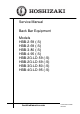
Service Manual Back Bar Equipment Models HBB-2-59 (-S) HBB-2-69 (-S) HBB-3-80 (-S) HBB-4-95 (-S) HBB-2G-LD-59 (-S) HBB-2G-LD-69 (-S) HBB-3G-LD-80 (-S) HBB-4G-LD-95 (-S) hoshizakiamerica.
WARNING Only qualified service technicians should install and service the appliance. To obtain the name and phone number of your local Hoshizaki Certified Service Representative, visit www.hoshizaki.com. No installation or service should be undertaken until the technician has thoroughly read this Instruction Manual. Likewise, the owner/manager should not proceed to operate the appliance until the installer has instructed them on its proper operation.
IMPORTANT This manual should be read carefully before the appliance is serviced. Read the warnings and guidelines contained in this manual carefully as they provide essential information for the continued safe use, service, and maintenance of the appliance. Retain this manual for any further reference that may be necessary. CONTENTS Important Safety Information............................................................................................ 4 I. General Information...............................
Important Safety Information Throughout this manual, notices appear to bring your attention to situations which could result in death, serious injury, damage to the appliance, or damage to property. WARNING NOTICE IMPORTANT Indicates a hazardous situation which could result in death or serious injury. Indicates a situation which could result in damage to the appliance or property. Indicates important information about the use and care of the appliance.
WARNING, continued • Do not use an extension cord. • If the power cord is damaged, replace with factory-specified cord. • Do not use an appliance with a damaged power cord. The power cord should not be altered, jerked, bundled, weighed down, pinched, or tangled. Such actions could result in electric shock or fire. To unplug the appliance, be sure to pull the plug, not the cord, and do not jerk the cord. • Do not splash, pour, or spray water directly onto or into the appliance.
WARNING, continued • Do not block air inlets or outlets, otherwise cooling performance may be reduced. • Do not tightly pack the cabinet. Allow some space between items to ensure good air flow. Also allow space between items and interior surfaces. • Do not store unpackaged product in the appliance; the appliance is for prepackaged food and beverages only. • Certain products, if not stored in sealed containers, may accelerate corrosion of the evaporator, resulting in failure; keep all containers closed.
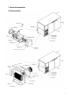
I. General Information A.
B.
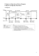
II. Sequence of Operation and Service Diagnosis A. Sequence of Operation Flow Charts 1.
B. Service Diagnosis WARNING The appliance should be diagnosed and repaired only by qualified service personnel to reduce the risk of death, electric shock, serious injury, or fire. Risk of electric shock. Use extreme caution and exercise safe electrical practices. Moving parts (e.g., fan blade) can crush and cut. Keep hands clear. Make sure all food zones are clean after the appliance is serviced. NOTICE The appliance is not intended for outdoor use.
1. Factory Default Setting: a) Temperature Settings: 32°F. b) Temperature Display Scale: °F. For further details, see "II.C.Controller Check" or "III.Controller and Adjustments." Note: • When exposed to high temperatures, a high-temperature alarm "Hi" may occur at startup. To silence the alarm, press and release the “SET” button. Alarm automatically resets when temperature drops to an acceptable range. • There is a minimum 3-min. Comp on time and 3-min. Comp off time.
c) Comp and CondFM Diagnosis: Confirm Comp and CondFM energize after the 3-min. of delay at the power on. If not, check if the compressor icon appears in the remote display, if not check the set point and the temperature in the remote display, if the temperature is not in proper range check the CTh status. See "II.D. Thermistor check”, If CTh ohm reading is in proper range replace controller.
C. Controller Check 1. Controller Before replacing Controller that does not show a visible defect and that you suspect is bad, conduct the following check procedure. This procedure will help you verify your diagnosis. Always choose a neutral to establish a good neutral connection when checking high voltages. Also, confirm there is a good power supply and neutral connection to controller: 115VAC at terminals #6 (Brown) to neutral #7 (White).
D. Thermistor Check The cabinet thermistor (NTC type) is used for cabinet temperature control; the thermistor resistance varies depending on temperature. The controller monitors the thermistors to control system operation. No adjustment is required; the controller has the adjustment from factory. In the event the cabinet thermistor reading is out of range (E0 alarm), the compressor operates on a fixed time basis of 20-min. on and 15-min. off. To check thermistor resistance, follow the steps below.
E. Diagnostic Tables Check for correct appliance installation per the instruction manual and proper voltage per appliance nameplate. 1. Not Cooling Not Cooling - Possible Cause 1. Power Supply 2. Cord and Plug On threesection model, check receptacle box cord and plug and one-section and two-section cords and plugs 3. Power Switch (control box) 4. Wiring 5. Controller, See "III.D. Alarm Safeties" and "II.C. Controller Check" 6. Evaporator Fan Motor 7. Compressor Relay 8. Compressor Protector 9.
2. Evaporator Frozen Up Evaporator Frozen Up - Possible Cause 1. Evaporator a) Dirty. 2. Evaporator Fan Motor a) Fan blades binding. b) Defective. 4. Controller a) Defective. 5. Compressor Relay a) Defective. 6. Refrigerant Charge/Refrigerant a) Low. Lines b) Component restriction (cap tube, drier). 3. Defrost: Controller Refrigerator Defrost Fails to Initiate - Possible Cause 1. Compressor Relay a) Defective. 2. Controller a) Defective. b) Energy loss or restored before the compliance of 6-hr.
III. Controller and adjustments A. Controller with Integrated Display 1. Controller with Integrated Display All models are pretested and factory set. NOTICE • The controller is fragile, handle very carefully. • Do not change wiring and connections. Never misconnect terminals. • Do not short out power supply to test for voltage.
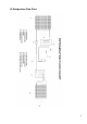
b) Controller Location and Layout Door to access condensing unit and control box.
In setpoint mode press to raise temperature, otherwise press and hold to turn compressor on or off without unplugging or using power switch. Cabinet Temperature Compressor Icon Press to change the temperature setpoint. In setpoint mode press to lower temperature, otherwise press and hold to initiate manual defrost.
B. Temperature The temperature default scale is °F, but it can be changed to read °C. To change, see "III.B.3. Changing the Temperature Display Scale (°F or °C)". 1. Default Settings a) Temperature Setting: 32°F. b) Temperature Display Scale: °F. c) Differential temperature: 6°F (3.3°C) to turn ON the Comp and CondFM. 2. Temperature Set Point The unit comes with a factory default setpoint of 32°F. If setpoint needs to be changed, follow the steps below. Press the “SET” button for two seconds.
3. Changing the Temperature Display Scale (°F or °C) To change from °F to °C, access the controller program mode. Press and hold the "SET" button for 5 sec. "PS" appears in the display. Release the "SET" button. Press the "SET" button again, "0" is displayed. With the "UP" arrow button, scroll until "22" is displayed, then press the "SET" button. "PS" is displayed. With the "DOWN" arrow button, scroll until "EZY" is displayed. Press the "SET" button. "1" is displayed.
D. Alarms Safeties Alarm signals are designed to protect the appliance and the beverage product. These alarms give information or warnings in the event the appliance is operating out of acceptable parameters. Should one of the alarms occur, follow the instructions in the table below to address the alarm. The alarm code flashes once every second with audible alarm. To silence the alarm, press and release the “SET” button. 1.
IV. Replace of Components WARNING • The appliance should be diagnosed and repaired only by qualified service personnel to reduce the risk of death, electric shock, serious injury, or fire. • Move the power switch to the "OFF" position then unplug the appliance from the electrical outlet before servicing. • Make sure all food zones in the appliance are clean after the appliance is serviced. A.
1. Refrigerant Recovery The appliance is provided with refrigerant access valves. Using proper refrigerant practices recover the refrigerant from the access valves and store it in an approved container. Do not discharge the refrigerant into the atmosphere. 2. Brazing WARNING • R-134a is not flammable at atmospheric pressure and temperatures up to 176°F (80°C). • R-134a is not explosive or poisonous.
3. Evacuation and Recharge 1) Attach a vacuum pump to the system. Be sure the charging hoses are connected to low-side access valves. NOTICE The vacuum level and vacuum pump may be the same as those for current refrigerants. However, the rubber hose and gauge manifold to be used for evacuation and refrigerant charge should be exclusively for POE oils 2) Turn on the vacuum pump. Open the gauge manifold valves. Never allow the oil in the vacuum pump to flow backwards.
B. Important Notes for Component Replacement WARNING • When replacing a component listed below, see the notes to help ensure proper operation. Components Notes Compressor Install a new start relay, start capacitor, and compressor protector (compressor protector is integrated with the start relay). Compressor, WARNING! To reduce the risk of electric shock, be sure to Evaporator reconnect the component's ground wire.
VI. Preparing the Appliance for Periods of Non-Use WARNING • When preparing the appliance for long storage, prevent the doors from closing to reduce the risk of children getting trapped. • To reduce the risk of electric shock, do not touch the attachment plug or power witch with damp hands. • When shutting down the appliance for more than one week, move the power switch to the "OFF" position and unplug the appliance. • Do not plug in/unplug the appliance to start/stop operation.
VIII. Technical Information A. Electrical and Refrigeration Data See the nameplate for electrical and refrigerant data. The nameplate is located inside the cabinet at the left side. BACK BAR Models (Solid Doors) HBB-2-59 (-S) HBB-3-69 (-S) HBB-3-80 (-S) HBB-4-95 (-S) BACK BAR Models (Glass Doors) HBB-2G-LD-59 (-S) HBB-3G-LD-69 (-S) HBB-3G-LD-80 (-S) HBB-4G-LD-95 (-S) Operation Temp Max. Amps 5.1 5.1 5.1 5.
B.