NO. J002-794 ISSUED: APR. 1, 2011 REVISED: SEP.
IMPORTANT Only qualified service technicians should install, service, and maintain the unit. No service or maintenance should be undertaken until the technician has thoroughly read this Service Manual. Failure to service and maintain the equipment in accordance with this manual may adversely affect safety, performance, component life, and warranty coverage. Hoshizaki provides this manual primarily to assist qualified service technicians in the maintenance and service of the unit.
IMPORTANT This manual should be read carefully before the unit is serviced or maintenance operations are performed. Only qualified service technicians should install, service, and maintain the unit. Read the warnings contained in this booklet carefully as they give important information regarding safety. Please retain this booklet for any further reference that may be necessary. CONTENTS I. Specifications ------------------------------------------------------------------------------------------------ 1 A.
12. Special Modes ---------------------------------------------------------------------------------------22 III. Service Diagnosis ----------------------------------------------------------------------------------------24 A. Diagnostic Procedure ---------------------------------------------------------------------------------24 B. Error Codes ----------------------------------------------------------------------------------------------26 1.
Important Safety Information Throughout this manual, notices appear to bring your attention to situations which could result in death, serious injury, or damage to the unit. WARNING Indicates a hazardous situation which could result in death or serious injury. NOTICE Indicates a situation which could result in damage to the unit or property. IMPORTANT Indicates important information about the use and care of the unit.
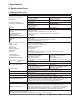
I. Specifications A. Specification Sheet 1.
2. JWE-2400CUA-R-25B AC SUPPLY VOLTAGE POWER SUPPLY CAPACITY AMPERAGE STARTING AMPERAGE ELECTRICAL COMSUMPTION HEATER RACK SIZE NUMBER OF LARGE DISHES / RACK CAPACITY WATER COMSUMPTION PASSING HEIGHT DIRECTION OF OPERATION OUTSIDE DIMENSIONS EXTERIOR DOOR LEG WASH SYSTEM ,RINSE SYSTEM PUMP DRAIN SYSTEM START DRY SYSTEM REFUSE DISPOSAL DETERGENT DISPLAY TANK CAPACITY HOT WATER SUPPLY TEMPERATURE CONTROL DISHWASHER SIDE BOOSTER SIDE 3 phase 3-wire 208-230V/60Hz (±10%) / 2 power supply lines㩷 208V : 18.
B. Nameplate Rating For certification marks, see the nameplate on the dishwasher. We reserve the right to make changes in specifications and design without prior notice.
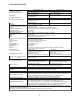
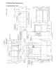
C. Dimensions/Connections Units: mm [in.] 1.
Units: mm [in.] 2.
II. General Information A. Construction 1. Dishwasher The illustration below shows JWE-2400CUA-L-25B (left-to-right rack flow).
Sheathed Heater [H7 - 15] 2.
Fan Buzzer Fan Motor 8 Control Transformer (Control Board) Control Board Conveyor Speed Switch Terminal Block TB1: For Dishwasher TB2: For Booster Tank Phase Reversal Relay Main Transformer (Control Supply) Magnetic Contactor MC5 - 7: Booster Tank Heater Contactors (MC5: upper, MC6: lower left, MC7: lower right) Terminal Block TB3: Detergent/Rinse Aid Feeder Inverter * NOTICE: To prevent failure, do not change settings.
B. Functions Upper Rinse Spray Arm 1. Increasing Rinse Water Flow Rate Clean Pipe The rinse water flow rate is factory adjusted to 1.90 gal/min (7.2 L/min). To increase the flow rate to 3.17 gal/min (12 L/ min), follow the steps below. Hot water supply of at least Lower Rinse 3.44 gal/min (13 L/min) and 113°F (45°C) will be required. Spray Arm 1) 2) 3) 4) Nut Remove the upper and lower rinse spray arms. Spacer Loosen the clean pipe nut, and remove the clean pipe. Remove the spacer (with 4.
4. If BT WLF/S fails, BT BUWLF/S assumes control. If BT BUWLF/S remains closed for 1 minute, o1 or o2 error appears in the display. For details, see "III.B. Error Codes." 5. The wash/rinse start switch is inactive during the auto fill cycle. 2. Ready Cycle (Unit Inactive) "READY" lamp and "RINSE TEMP." or "WASH TEMP." lamp on. WT WLS closed. After a rinse cycle, RPM de-energizes, and the "READY" lamp comes on. WTH energizes when WT water temperature is at the wash temperature setpoint or lower.
WT. The conveyor does not start during the supplementary fill cycle. "A3" appears in the display and the "AUTO FILL" lamp flashes. BZ beeps three times only at the beginning. If WT WLS is still open after the supplementary fill cycle, another cycle starts. If WT WLS still does not close, "A3" appears in the display, BZ beeps and the unit shuts down. For adjustment of the supplementary fill cycle time, see "Supplementary Fill Cycle Time" (service menu item 07) in "II.F.7.b) Service Menu Chart.
Initial startup begins here Cycle Steps WT WLS check 12 Legend: BT–internal booster tank BTH–internal booster tank heater DFT–detergent feeder terminals GM-gear motor (conveyor) RFT–rinse aid feeder terminals RPM–rinse pump motor RSS-rinse start switch SPS–service panel switch VFCT-vent fan control terminals WLF/S–water level float switch WLS–water level sensor WLSF/S-water level safety float switch WPM–wash pump motor WSS-wash start switch WT–wash tank WTH–wash tank heater WV–inlet water valve "A1" er
ON OFF ON OFF ON OFF CLOSED OPEN ON OFF ON OFF "AUTO FILL" Lamp "READY" Lamp "WASH" Lamp Service Panel Switch Rinse Pump Water Valve CLOSED OPEN Booster Tank 13 CLOSED OPEN ON OFF ON OFF Water Level Sensor Buzzer Wash Tank Heater Note 1 * Factory default, adjustable by service menu Note 3 Service menu item 03 Approx. 13 gal (50L) water level Note 1 (Repeat) Auto Fill Cycle Rinse Time (*13 min) 2 gal (7.
14 ON OFF Wash Tank Heater Delay Time (0.5 sec) * Factory default, adjustable by service menu Load rack Note 4 Note 3 Note 2 Service menu item 02 Note 4 Extended Rinse Cycle Time (*15 sec) Service menu item 01 Extended Wash Cycle Time (*30 sec) Note 1 Note 4: The rack handle shape opens the wash/rinse start switch for a moment. But the extended wash/rinse cycle time prevents interruption of the wash/rinse cycle.
F. Control Board and Operation Board • A Hoshizaki exclusive solid-state control board and operation board are employed in all Hoshizaki dishwasher units. • All models are pretested and factory set. NOTICE 1. The control board and operation board are fragile; handle very carefully. 2. The control board and operation board contain integrated circuits, which are susceptible to failure due to static discharge.
2. Control Board Layout Inputs and outputs are laid out on the control board as illustrated below.
3. Control Board Diagram 200VAC from Transformer Transformer 11V 7.
4. Operation Panel Layout The operation panel is mounted on top of the unit (wash compartment exit side) and is connected to the CN5 connector on the control board. Up Button Water Temperature Lamps Down Button "AUTO FILL" Lamp Display "READY" Lamp "CHANGE" Button "WASH" Lamp "ON/OFF" Button 5. Features a) Display This operation board uses an LED display to show system details and diagnostic information.
c) "READY" Lamp Lights up when the auto fill cycle completes and the dishwasher is ready to wash. d) "WASH" Lamp Lights up during washing operation. e) Up Button, Down Button Indicates the total hours of operations in six digits by two digits each time. Example: 123,456 hours are indicated by Press to stop the beep in case of error. Service personnel also use these buttons to change the controller settings.
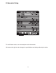
b) Service Menu Chart Service Item and Details Menu 01 Extended Wash Cycle Time Setting Range Display Factory Default 30 1 to 99 seconds 1 to 99 (in 10 second steps) 02 Extended Rinse Cycle Time 1 to 99 seconds 1 to 99 15 (in 1 second steps) 03 Auto Fill Cycle Rinse Time 0 to 99 minutes 0 to 99 13 (in 1 minute steps) 04 Wash Temperature Setpoint Fahrenheit 32 to 176°F 32 to 176 163 (in 1°F steps) Celsius 0 to 80° 0 to 80 73 (in 1°C steps) 05 Rinse Temperature Setpoint Fahrenheit 32 to 185°F 32 to 185 18
8. Temperature Display • Indicates the average water temperature read by the wash tank or booster tank thermistor. Indicates water temperature selected by the water temperature lamps beside the display. The factory default setting is to indicate wash water temperature and rinse water temperature alternately every 5 seconds.
11. Operation Time Display To indicate the total hours of operation in the display, press the up button on the operation panel. The number appears from the hundred-thousands place by two digits each for 1 second. The maximum number is 999,999 hours, and the display does not change for the higher numbers. Example: 19,302 hours are indicated as 12. Special Modes OFF OFF a) Continuous Wash Mode The continuous wash mode (also used when descaling) allows the wash pump motor to run continuously.
4) Set service menu item 19 to ON to stop the beep when the "ON/OFF" button is switched off but to resume flashing "Ch" when the "ON/OFF" button is switched back on unless the wash water tank is refilled (factory default: OFF). Press the emergency stop button or turn off the external power supply to stop both the beep and "Ch" indication. Set service menu item 19 to OFF to stop both the beep and "Ch" indication once the "ON/ OFF" button is switched off.
III. Service Diagnosis WARNING 1. This unit should be diagnosed and repaired only by qualified service personnel to reduce the risk of death, electric shock, serious injury, or fire. 2. Risk of electric shock. Use extreme caution and exercise safe electrical practices. 3. Moving parts (e.g., fan blade) can crush and cut. Keep hands clear. 4. Do not make any alterations to the unit. This could cause water leak, electric shock, or fire. 5.
It is recommended to conduct this sequence check in the auto fill cycle after draining the wash tank and booster tank. See “II.C. Sequence of Operation” for further details. 1) 2) 3) 4) 5) 6) Use the “ON/OFF” button on the operation panel to turn off the unit. Pull out the overflow pipe to drain the wash tank. Drain the booster tank through the drain hose. Replace the overflow pipe and drain hose in their correct positions. Enter the switch open/closed display mode according to the above procedure.
B. Error Codes In the event of operation outside of normal parameters, the control board identifies the issue with an error code. For further service information, see "III.C. Service Flow Charts." 1. Error Code Table Error Problem Code Wash Tank Auto Fill Error A1 A2 A3 o1 o2 H1 H2 H3 Water level in wash tank does not reach water level sensor after rinse pump has run for preset time.
Error Problem Code Booster Tank Thermistor Error (open) H4 H5 H6 L1 L2 b1 b2 Thermistor senses abnormal temperature (at or below -6°F (-21°C)). ROM/RAM Error Control board ROM/RAM fails. EEPROM Error EEPROM fails. Conveyor Overload or Table Limit Error 1 Operation Reset Normal (Booster tank heaters off) After replacing failed component, alarm resets. Whole unit stops After replacing control board, alarm resets. Whole unit stops After replacing control board, alarm resets.
3. Error Code Details a) Auto Fill Error (A1) • If the water level sensor in the wash tank is not closed at the end of the auto fill cycle, the unit shuts down, "A1" appears in the display, and the buzzer sounds. • To reset, use the "ON/OFF" button to turn the unit off and then back on. • See the chart below for possible causes and remedies. Code A1 Error Wash tank water level sensor is open at the end of the auto fill cycle. Operation Unit stops.
Continue Booster Tank Water Level Float Switch Sticking (with float in “ON” position). Check and clean. See “III.D. Float Switch Check and Cleaning.” Defective (with internal contacts in “ON” position). Replace.
b) Booster Tank Auto Fill Error (A2) • In the auto fill cycle, if the booster tank water level float switch does not close within 10 minutes (or 20 minutes in "READY" mode) after the cycle starts, the unit shuts down, "A2" appears in the display, and the buzzer sounds. • To reset, use the "ON/OFF" button to turn the unit off and then back on. • See the chart below for possible causes and remedies.
c) Wash Tank Water Level Error (A3) • If the water level in the wash tank goes below the water level sensor in "READY" mode or during operation, the supplementary fill cycle starts, "A3" appears in the display, the "AUTO FILL" lamp flashes, and the buzzer sounds three times only at the beginning. • If the wash tank water level sensor is closed after the supplementary fill cycle, the alarm resets. If the wash tank water level sensor is still open after the supplementary fill cycle, another cycle starts.
d) Booster Tank Water Level Error 1 (Booster Tank Water Level Float Switch Closed) (o1) • If both the booster tank water level float switch and the booster tank backup water level float switch have remained closed for 1 minute, the booster tank heaters de-energize, "o1" appears in the display, and the buzzer sounds. • The error resets if the booster tank backup water level float switch opens or when the "ON/ OFF" button is used to turn the unit off and then back on.
e) Booster Tank Water Level Error 2 (Booster Tank Water Level Float Switch Open) (o2) • If the booster tank water level float switch is open and the booster tank backup water level float switch has remained closed for 1 minute, the booster tank heaters de-energize, "o2" appears in the display, and the buzzer sounds. • The error resets if the booster tank backup water level float switch opens or when the "ON/ OFF" button is used to turn the unit off and then back on.
f) Wash Tank Thermistor Error (H1, H2) • If the wash tank thermistor senses a temperature at or above 231°F (111°C) (2.4kΩ), the thermistor leads are considered shorted and the wash tank heaters de-energize, "H1" appears in the display, and the buzzer sounds. • If the wash tank thermistor senses a temperature at or below -6°F (-21°C) (517kΩ), the thermistor leads are considered open and the wash tank heaters de-energize, "H2" appears in the display, and the buzzer sounds.
g) Booster Tank Thermistor Error (H3, H4) • If the booster tank thermistor senses a temperature at or above 231°F (111°C) (2.4kΩ), the thermistor leads are considered shorted and the booster tank heaters de-energize, "H3" appears in the display, and the buzzer sounds. • If the booster tank thermistor senses a temperature at or below -6°F (-21°C) (517kΩ), the thermistor leads are considered open and the booster tank heaters de-energize, "H4" appears in the display, and the buzzer sounds.
h) ROM/RAM Error (H5) • If a ROM/RAM error is detected, the unit shuts down, "H5" appears in the display, and the buzzer sounds. • After replacing the failed component, the alarm resets. • See the chart below for possible causes and remedies. Code H5 Operation Error ROM/RAM on control board fails. Unit stops. Item Possible Cause Defective. Control Board Remedy Replace. i) EEPROM Error (H6) • If an EEPROM error is detected, the unit shuts down, "H6" appears in the display, and the buzzer sounds.
j) Conveyor Overload or Table Limit Error 1 (L1) • If the inverter sends an overload signal or the table limit switch closes, the unit shuts down, "L1" appears in the display, and the buzzer sounds. • After removing the jammed rack or the cause of the overload (the table limit switch opens or the inverter stops sending the overload signal), the alarm resets after 3 seconds, and the unit is ready to resume operation.
k) Conveyor Overload or Table Limit Error 2 (L2) • If the unit shuts down with "L1" in the display and restarts in 3 seconds after the cause of the overload is removed, and the inverter sends another overload signal within 3 seconds after the conveyor moves, the unit completely shuts down, "L2" appears in the display, and the buzzer sounds. • To reset, use the "ON/OFF" button to turn the unit off and then back on.
l) Booster Tank Error (b1) • If the booster tank error input contacts stay open for more than 2 seconds, "b1" appears in the display, and the buzzer sounds. • If the booster tank error input contacts stay closed for more than 2 seconds, the alarm resets. Note: The booster tank error input must be connected to indicate this error code. Code b1 Operation Error Booster tank sends error signal. Continues. Item Booster Tank Control Board Connection Cable Possible Cause Remedy Defective.
m) Booster Tank Water Level Safety Error (b2) • If the booster tank water level safety float switch opens after the booster tank water level float switch closes, the unit shuts down, "b2" appears in the display, and the buzzer sounds. • To reset, use the "ON/OFF" button to turn the unit off and then back on. Code b2 Error Booster tank water level safety float switch opens after booster tank water level float switch closes.
C. Service Flow Charts 1. Unit Will Not Start Unit will not start Problem Main Power Supply Emergency Stop Button ON/OFF Button Possible Cause Off, blown fuse, or tripped or defective circuit breaker. Turn on, replace, or check and reset. Call electrician if breaker trips repeatedly. Loose connection. Tighten. Not within specifications. Refer to nameplate and correct. Pressed. Turn clockwise to reset. “OFF” position. Move to “ON” position. Wait for recovery.
Continue Transformer Wiring to Control Board Control Board Open coil winding. Replace. Loose connections or open. Check continuity and repair or replace. In alarm. See “III.B. Error Codes.” Defective. Replace.
2. Dishes Not Clean Dishes not clean Problem Low Wash Pump Output Wash Spray Arms Filter Dish Rack Dishes Possible Cause Remedy Clogged with foreign matter. Clean. Voltage drop. Remove cause. Vapor lock due to clogged tank filter. Clean tank filter. Vapor lock due to use of neutral cleaner. Stop using neutral cleaner. Wash pump defective. Replace. Clogged. Clean. Out of position. Set in position. Low pump output. See “Low Wash Pump Output”. Out of position. Place in position.
Continue Detergent Wash Tank Water Heater Not Energized Conveyor Speed Voltage No supply. See “III.C.5. No or Inadequate Detergent/Rinse Aid Supply.” Insufficient supply. Refill or adjust detergent feeder. Unspecified detergent used. Use specified detergent only. Dirty. Drain wash tank and supply fresh hot water. Temperature too low. Raise setting or see “Heater Not Energized”. Temperature will not rise. Reset overheat thermostat. Control output error.
3. Inadequate Rinse Inadequate rinse Problem Low Rinse Pump Output Rinse Spray Arms Dish Rack Rinse (Booster Tank) Water Rinse Cycle Time Voltage Possible Cause Remedy Clogged with foreign matter. Clean. Rinse water line scaled. Clean. Voltage drop. Remove cause. Rinse pump defective. Replace. Clogged. Clean. Out of position. Set in position. Low pump output. See “Low Rinse Pump Output.” Improperly loaded. Load correctly. Temperature too low.
4. Dishwasher Will Not Start Wash/Rinse Cycle Dishwasher will not start wash/rinse cycle Problem Wash Pump Inoperative Rinse Pump Inoperative Service Panel Magnet Detection Error Wash Start Switch Rinse Start Switch Possible Cause Remedy Protector tripped. Wait until wash pump cools. Locked with foreign matter. Remove obstacles. Controller input/output error. Check input/output and repair or replace. Magnetic contactor defective. Replace. Protector tripped. Wait until Rinse Pump cools.
5. No or Inadequate Detergent/Rinse Aid Supply No or inadequate detergent/rinse aid supply Problem Detergent/Rinse Aid Supply Line (Injector, Vinyl Hose, Strainer) Detergent Pump Possible Cause Remedy Empty. Refill. Clogged or kinked. Clean or straighten. Air in line. Purge air. Supply volume too low. Set to proper volume. Defective. Replace. 6.
7. Wash Tank Water Not Draining Wash tank water not draining Problem Drain Hose Drain Pipe (Overflow Pipe) Possible Cause Remedy Clogged. Unclog. Pinched. Correct. Raised. Correct. Clogged. Unclog.
D. Float Switch Check and Cleaning (for Booster Tank Water Level Float Switch and Backup Water Level Float Switch) If an abnormal input signal is found by “III.A. Diagnostic Procedure” or the error code “o1” or “o2” is displayed, check and clean/replace the float switches according to the procedure below. 1. Float Switch Check To check the float switches, follow the steps below.
E. Thermistor Check If the error code “H1” “H2” “H3” or “H4” or an abnormal temperature [above 231°F (111° C) or below -6°F (-21°C)] appears in the display, or the wash tank water boils, check the thermistor(s) according to the procedure below. If replacement is required, see “IV.H. Removal and Replacement of Thermistor.” 1) Use the “ON/OFF” button on the operation panel to turn off the unit, then turn off the dishwasher and booster tank power supplies.
IV. Removal and Replacement of Components WARNING 1. This unit should be diagnosed and repaired only by qualified service personnel to reduce the risk of death, electric shock, serious injury, or fire. 2. Use the “ON/OFF” button on the operation panel to turn off the unit, then turn off the dishwasher and booster tank power supplies. Lockout/Tagout to prevent the power supplies from being turned back on inadvertently. 3.
4) Make sure the O-rings are in place, and attach the wash pump motors to the tank discharge outlets and suction inlets. Secure the connections with the bands. 5) Tighten the bracket mounting screws. 6) Fill the tank with water, then check for water leaks from the joints. If there is a water leak, check the connections, and retighten the bands. If there are no water leaks, drain the tank. 7) Connect the wiring.
6) Disconnect the rinse pump motor wiring at the closed end connectors. 7) Remove the nut from the flexible tube at the rinse pump motor discharge outlet and the bolts securing the bracket to the unit base. 8) Remove the band from the pipe joint of the booster tank discharge pipe behind the rinse pump motor and the flexible tube at the rinse pump motor suction inlet. Pull the end of flexible tube out of the booster tank discharge pipe. Note: Use a hand mirror for easy removal.
[JWE-2400CUA-L-25B] * View without rinse pump motor Booster Tank Discharge Pipe Band Rinse Pump Motor Suction Inlet Flexible Tube Rinse Pump Motor Band Booster Tank Discharge Pipe Rinse Pump Motor Suction Inlet Flexible Tube 54
D. Removal and Replacement of Gear Motor 1) Use the “ON/OFF” button on the operation panel to turn off the unit, then turn off the dishwasher and booster tank power supplies. Lockout/Tagout to prevent the power supplies from being turned back on inadvertently. 2) Remove the front panel. 3) The gear motor is located behind the control box and at the rear left side of the machine compartment (JWE-2400CUA-L-25B) or located at the rear right side of the machine compartment (JWE-2400CUA-R-25B).
E. Removal and Replacement of Conveyor 1) 2) 3) 4) 5) Remove the 4 bolts (2 at rear, 2 at both sides) securing the rear rack rail. Hold the conveyor, and lift off the rear rack rail. Slider Take out the conveyor. Remove the left and right frames from the conveyor. Remove the 5 nuts each of the conveyor rails to release the hooks and the bearings. 6) To replace, reverse the above procedure. Note: Be careful of the slider direction when fitting the conveyor on the crankshaft slider.
F. Removal and Replacement of Crankshaft To remove: 1) Remove the front panel. 2) Remove the conveyor. 3) Loosen the 6 hexagon socket set screws for the stopper and the coupling. 4) Lift off the crank together with the shaft. 5) Loosen the screw securing the crank to release the crank from the shaft. Note: Do not disassemble the housing, oil seals and bearing. To replace: 1) Fit the housing (up) on the housing, and put the sleeve bearing and the crankshaft into the housing.
G. Removal and Replacement of Control Box WARNING Do not touch the live parts during a trial run or servicing operations. NOTICE Be careful not to damage the wiring when handling the control box. 1) Use the “ON/OFF” button on the operation panel to turn off the unit, then turn off the dishwasher and booster tank power supplies. Lockout/Tagout to prevent the power supplies from being turned back on inadvertently. 2) Remove the front panel. 3) Slide out the control box. 4) Remove the control box cover.
2) Remove the front panel. 3) Slide out the control box. 4) Remove the plastic bag covering the thermistor connector, then disconnect the thermistor connector. If replacing the wash tank thermistor, disconnect the leads from the wash tank electrode. If replacing the booster tank thermistor, disconnect the closed end connectors for the booster tank water level float switch and the booster tank backup water level float switch.
3) 4) 5) 6) Disconnect the control board connectors from the control board. Slide out the control board. Install the new control board. To replace, reverse the above procedure. 2. Operation Board 1) Use the “ON/OFF” button on the operation panel to turn off the unit, then turn off the dishwasher and booster tank power supplies. Lockout/Tagout to prevent the power supplies from being turned back on inadvertently.
J. Removal and Replacement of Heater When replacing the wash tank heater or the booster tank heater, remove the nuts using a 7/8" crowfoot wrench. When replacing the booster tank heater, move the clean dishtable above the booster tank before following the procedure below. 1) Use the “ON/OFF” button on the operation panel to turn off the unit, then turn off the dishwasher and booster tank power supplies. Lockout/Tagout to prevent the power supplies from being turned back on inadvertently.
* The illustration shows the boster tank heater Bolt Heater Band Nut Cross-section: band fitting Washer Band Heater Square Hole K. Removal and Replacement of Float Switch When replacing the float switch, move the clean dishtable above the booster tank before following the procedure below. 1) Use the “ON/OFF” button on the operation panel to turn off the unit, then turn off the dishwasher and booster tank power supplies.
L. Removal and Replacement of Thermostat NOTICE Always use the recommended sealant (high thermal conductive type), Model KE4560RTV manufactured by SHINETSU SILICONE, Part Code 60Y000-11, or Part Code 4A0683-01 or equivalent. When replacing the thermostat in the wash water tank or the booster tank, remove the thermostat, clear any remaining sealant from the tank walls, apply a proper amount of the above recommended sealant to the new thermostat bulb, then install the new thermostat in its correct position.
V. Cleaning and Maintenance Instructions A. Daily Maintenance IMPORTANT Be sure to clean the dishwasher after closing time every day. It is difficult to remove heavy soils left overnight. In high temperature conditions, food scraps will rot and affect sanitary operation. 1) Remove the three curtains at the entrance, center, and exit of the wash compartment. 2) Open the service panel.
6) To remove the lower rinse spray arm, push down the rising part to unhook, pull off the end of the pipe towards you, then take it out from between the rack rails. 7) Remove the separators. 8) Take out scraps from the removed tank filters, drain pipe and separators, and wash them clean with a scouring pad. IMPORTANT To prevent damage, do not hit the filters on the sink to drop scraps or to drain the filters.
11) Clean the wash compartment. Remove any scraps from inside the wash compartment and wash tank. Use a scouring pad to wash off heavy soils. Remove any silverware left inside the wash compartment. Silverware 12) Check the pump filters inside the wash tank. If they are clogged, clean them with a scouring pad. Pump Filter 13) Check the water level sensor. If it is dirty, clean it with a soft brush. IMPORTANT Do not use a metal brush to clean the water level sensor.
17) To replace the upper wash spray arm, hold it with the nozzles facing down, and insert the joint into the pipe located at the back of the wash compartment. Lift up the front, then securely hook in the square hole. Hook 18) To replace the lower wash spray arm, hold both sides with the nozzles facing up, and put it under the rack rails from the front. Insert the joint into the pipe located at the back of the wash compartment. Fit the holes on the pins at the front of the wash tank.
20) To replace the lower rinse spray arm, put it between the rack rails, insert the end of the pipe into the joint, then turn and hook the front. Ring 21) Install the curtain (L) in the wash compartment. Curtain Rod (longer) 22) Install the curtains (S) at the entrance and exit of the wash compartment.
23) Close the service panel. WARNING To prevent entrance of dust or insects and injuries by a sudden drop, do not leave the service panel open. B. Weekly Maintenance 1. Heater WARNING To prevent burns, wait for 10 minutes after draining the unit to clean the interior. Soft Brush Remove any scraps from the heater, and use a soft brush to wash off residue. Heater Do not use a metal brush which may damage the surface. 2. Exterior 1) Wipe the exterior with a soft cloth.
D. Descaling (As Required) Use a descaler according to the supplier’s instructions. WARNING 1. Carefully follow any instructions provided with the descaler. 2. Always wear liquid-proof gloves and goggles to prevent the descaler from coming into contact with skin or eyes. 3. To prevent generation of toxic chlorine gas, do not mix a descaler with a chlorinated cleaner. 1) Pull out the drain pipe to drain water from the wash tank. Start the auto fill cycle to fill the wash tank with hot water.
1) Press the “ON/OFF” button on the operation panel. The display and lamps go off. 2) Turn off the water heater. 3) Turn off the gas and water supplies. IMPORTANT To operate the water heater, follow its instruction manual. Service Panel 4) Open the service panel. Hook IMPORTANT Be sure to hook the service panel in its open position. 5) Pull out the drain pipe to drain water from the wash tank. WARNING When pulling out the drain pipe, be careful not to touch the wash water.
F. Long Storage, Relocation, Disposal, Transfer When preparing the unit for long storage, shut down and clean the unit according to sections A - E. If something seems wrong when restarting the unit after long storage, turn off the power supply, and immediately contact an authorized Hoshizaki service company. WARNING 1. When restarting the unit after long storage, contact an authorized Hoshizaki service company. To prevent electric shock, do not restart the unit by yourself. 2.
VII. Technical Information A.
B.