Hoshizaki Hoshizaki America, Inc. Stackable Crescent Cuber Models KMH-2000SWH/3 KMH-2000SRH/3 “A Superior Degree of Reliability” INSTRUCTION MANUAL www.hoshizaki.
IMPORTANT Only qualified service technicians should install, service, and maintain the icemaker. No installation, service, or maintenance should be undertaken until the technician has thoroughly read this Instruction Manual. Likewise, the owner/ manager should not proceed to operate the icemaker until the installer has instructed them on its proper operation.
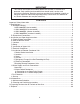
IMPORTANT This manual should be read carefully before the icemaker is installed and operated. Only qualified service technicians should install, service, and maintain the icemaker. Read the warnings contained in this booklet carefully as they give important information regarding safety. Please retain this booklet for any further reference that may be necessary. CONTENTS Important Safety Information.................................................................................................. 4 I.
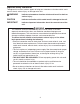
Important Safety Information Throughout this manual, notices appear to bring your attention to situations which could result in death, serious injury, or damage to the unit. WARNING Indicates a hazardous situation which could result in death or serious injury. CAUTION Indicates a situation which could result in damage to the unit. IMPORTANT Indicates important information about the use and care of the unit.
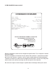
I. Specifications A. Nameplate Rating 1. KMH-2000SWH (water-cooled) HOSHIZAKI ICE MAKER MODEL NUMBER SERIAL NUMBER AC SUPPLY VOLTAGE KMH-2000SWH COMPRESSOR PUMP FAN OTHER MAXIMUM FUSE SIZE MAX. HACR BREAKER(USA ONLY) MAX. CIRC. BREAKER (CANADA ONLY) MINIMUM CIRCUIT AMPACITY DESIGN PRESSURE REFRIGERANT 208-230/60/1 (3 WIRE WITH NEUTRAL FOR 115V) 230V 11.1RLA 73LRA 120V 1.2FLA 60W - - 115V 0.3A 30 AMPS 30 AMPS 30 AMPS 30 AMPS HI-427PSI LO-230PSI 404A 3 LB. 1.4 OZ.
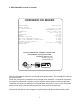
2. KMH-2000SWH3 (water-cooled) HOSHIZAKI ICE MAKER MODEL NUMBER SERIAL NUMBER AC SUPPLY VOLTAGE COMPRESSOR PUMP FAN OTHER MAXIMUM FUSE SIZE MAX. HACR BREAKER(USA ONLY) MAX. CIRC. BREAKER (CANADA ONLY) MINIMUM CIRCUIT AMPACITY DESIGN PRESSURE REFRIGERANT KMH-2000SWH3 208-230/60/3 230V 7.8RLA 66LRA 120V 1.2FLA 60W - - 115V 0.3A 20 AMPS 20 AMPS 20 AMPS 20 AMPS HI-427PSI LO-230PSI 404A 3 LB. 1.4 OZ. MOTOR-COMPRESSOR THERMALLY PROTECTED, NOT INTENDED FOR OUTDOOR USE! Hoshizaki America, Inc.
3. KMH-2000SRH (remote air-cooled) HOSHIZAKI ICE MAKER MODEL NUMBER SERIAL NUMBER AC SUPPLY VOLTAGE KMH-2000SRH COMPRESSOR PUMP FAN REMOTE OTHER MAXIMUM FUSE SIZE MAX. HACR BREAKER(USA ONLY) MAX. CIRC. BREAKER (CANADA ONLY) MINIMUM CIRCUIT AMPACITY DESIGN PRESSURE REFRIGERANT 208-230/60/1 (3 WIRE WITH NEUTRAL FOR 115V) 230V 10.9RLA 73LRA 120V 1.2FLA 60W 3A MAX 115V 0.
4. KMH-2000SRH3 (remote air-cooled) HOSHIZAKI ICE MAKER MODEL NUMBER SERIAL NUMBER AC SUPPLY VOLTAGE COMPRESSOR PUMP FAN REMOTE OTHER MAXIMUM FUSE SIZE MAX. HACR BREAKER(USA ONLY) MAX. CIRC. BREAKER (CANADA ONLY) MINIMUM CIRCUIT AMPACITY DESIGN PRESSURE REFRIGERANT KMH-2000SRH3 208-230/60/3 230V 7.9RLA 66LRA 120V 1.2FLA 60W 3A MAX 115V 0.3A 20 AMPS 20 AMPS 20 AMPS 20 AMPS HI-467PSI LO-230PSI 404A MOTOR-COMPRESSOR THERMALLY PROTECTED, NOT INTENDED FOR OUTDOOR USE! Hoshizaki America, Inc.
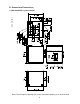
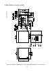
B. Dimensions/Connections Unit: mm [in.] 1. KMH-2000SWH/3 (water-cooled) Note: The storage bin opening must match the bottom opening as in the illustration.
Unit: mm [in.] 2. KMH-2000SRH/3 (remote air-cooled) Note: The storage bin opening must match the bottom opening as in the illustration.
II. Installation and Operating Instructions WARNING 1. This icemaker must be installed in accordance with applicable national, state, and local regulations. 2. CHOKING HAZARD: Ensure all components, fasteners, and thumbscrews are securely in place after installation. Make sure that none have fallen into the storage bin. A. Checks Before Installation • Visually inspect the exterior of the shipping container and immediately report any damage to the carrier.
C. Location CAUTION 1. This icemaker is not intended for outdoor use. Normal operating ambient temperature should be within 45°F to 100°F (7°C to 38°C); Normal operating water temperature should be within 45°F to 90°F (7°C to 32°C). Operation of the icemaker, for extended periods, outside of these normal temperature ranges may affect icemaker performance. 2. This icemaker will not work at sub-freezing temperatures.
b. Remove the tie securing the bin control thermostat assembly. Remove the 2 thumbscrews and the "Z" bracket. See Fig. 3. c. Remove the bin control thermostat assembly from the shipping hook. Lower the thermostat extension bracket (stainless) with the thermostat bulb attachment and thermostat bulb through the hole located at the bottom of the icemaker. Next, lower the thermostat bracket (plastic) through the hole. d.
6) Confirm that the icemaker and storage bin are level in both the left-to-right and front‑to‑rear directions. If necessary, level the storage bin in both the left‑to-right and front-to‑rear directions according to the storage bin manufacturer's instructions. 7) Replace the panels and baffle (if applicable) in their correct positions (unless you are installing an upper unit). See "II.E. Installation of Upper Unit." E. Installation of Upper Unit 1) See "II.D. Setup" for the lower unit installation.
7) Install the bin control thermostat as follows: a. Remove the thermostat bulb attachment (plastic) of the upper unit from the thermostat extension bracket (stainless). See Fig. 6. b. Carefully remove the thermostat bulb from the thermostat bulb attachment (plastic) of the upper unit, then remove the silicone hose from the capillary tube. c. Carefully route the thermostat bulb and capillary tubing of the upper unit through the bottom hole of the upper unit.
F. Electrical Connection WARNING For All Models 1. Electrical connection must be hard-wired and must meet national, state, and local electrical code requirements. Failure to meet these code requirements could result in death, electric shock, serious injury, fire, or extensive damage to equipment. 2. This unit requires an independent power supply. See the nameplate for proper voltage and breaker/fuse size.
• On three phase models, the transformer's voltage tap switch must be positioned to match incoming voltage at startup. • CAUTION! On three phase models, connect the highest incoming voltage supply ("stinger leg") to the red power supply wire (red common wire to the compressor). • The opening for the power supply connection is 7/8" DIA to fit a 1/2" trade size conduit.
G. Installation of Remote Condenser Unit WARNING 1. Installation of remote condenser unit must be performed by properly trained and EPA-certified service personnel. 2. Failure to install the equipment within these guidelines may adversely affect safety, performance, component life, and warranty coverage. 1. Checks Before Installation 1) Remove the shipping carton, tape, and packing material. 2) Check that the refrigerant lines do not rub or touch lines or other surfaces, and that the fan blades move freely.
3. Setup 1) Secure the legs to the remote condenser unit with the 8 bolts and nuts provided. See Fig. 10. 2) The legs have 8 mounting holes. Secure the legs with 8 bolts (not included). Bolts with Split Lock Washer and Flat Washer Fig. 10 Nuts Mounting Holes 4. Line Set CAUTION The icemaker, line set, and remote condenser unit must contain the same type of refrigerant. Mixing of refrigerants will result in improper operation and possible damage to the refrigeration system.
c. Make sure the male fitting and female coupling are properly aligned, then start the connection by hand to ensure that it is not cross threaded. d. Tighten the connection with a wrench until it is tight. At this point, the nut has covered most of the threads on the male fitting. e. Mark a reference line on the female coupling and the remote condenser unit or icemaker panel. Using a backup wrench on the back of the female coupling, tighten the six-sided nut of the female coupling an additional 1/6 turn.
6) Evacuate through the Schrader access ports on the Parker quick connect couplings and charge with R-404A refrigerant vapor to a pressure of 15 to 30 PSIG. 7) Connect the refrigerant lines to the appropriate male fittings on the remote condenser unit first and then at the icemaker. Make a proper connection as follows: a. Remove the protective covers from the male fitting and female coupling. b.
5. Refrigerant Charge (Line Set Exceeding 66 Feet) CAUTION The icemaker, line set, and remote condenser unit must contain the same type of refrigerant. Mixing of refrigerants will result in improper operation and possible damage to the refrigeration system. The maximum line length for the standard refrigerant charge is 66 feet. Should an installation require a longer line length, additional refrigerant must be added. Add 0.4 oz. of R-404A for each foot over 66 feet to a maximum of 100 feet.
4) Connect the fan motor leads in the junction box of the remote condenser unit to the fan motor leads in the fan motor junction box of the icemaker. Use wire of an appropriate gage and outdoor rating. 5) Replace the junction box covers and the louver panel in their correct positions. Remote Condenser Unit Icemaker Junction Box Cover Fan Motor Junction Box Cover Fig. 14 Screw Screws Louver Panel 7.
H. Water Supply and Drain Connections See Fig. 16, 17, or 18 WARNING 1. Water supply and drain connections must be installed in accordance with applicable national, state, and local regulations. 2. Normal operating water temperature should be within 45°F to 90°F (7°C to 32°C). Operation of the icemaker, for extended periods, outside of this normal temperature range may affect icemaker performance. 3.
1. Icemaker • Icemaker water supply inlet is 1/2" female pipe thread (FPT). A minimum of 1/2" nominal copper water tubing is recommended for the icemaker water supply line. • An icemaker water supply line shut-off valve and drain valve should be installed. • Icemaker drain outlet is 3/4" FPT. A minimum of 3/4" nominal hard pipe is recommended for the icemaker drain line. Condensation drain outlet is 3/8" OD hard tube.
2. Water-Cooled Condenser a) Connection to an Open Drain System • Condenser water supply inlet is 1/2" female pipe thread (FPT). A minimum of 3/8" nominal copper water tubing is recommended for the condenser water supply line. • A condenser water supply line shut-off valve and drain valve should be installed. • Condenser drain outlet is 3/8" FPT. A minimum of 3/8" nominal hard pipe is recommended for the condenser drain line.
b) Connection to a Closed Loop System • Condenser water supply inlet is 1/2" female pipe thread (FPT). A minimum of 3/8" nominal copper water tubing is recommended for the condenser water supply line. • Condenser return outlet is 3/8" FPT. A minimum of 3/8" nominal copper water tubing is recommended for the condenser return line. • Shut-off valves and drain valves should be installed at both the condenser water supply inlet and condenser return outlet.
I. Final Checklist WARNING CHOKING HAZARD: Ensure all components, fasteners, and thumbscrews are securely in place after installation. Make sure that none have fallen into the storage bin.
J. Startup WARNING 1. All parts are factory-adjusted. Improper adjustments may adversely affect safety, performance, component life, and warranty coverage. 2. If the icemaker is turned off, wait for at least 3 minutes before restarting the icemaker to prevent damage to the compressor. 3. To prevent damage to the water pump, do not leave the control switch in the "WASH" position for extended periods of time when the water tank is empty. 4.
III. Maintenance The appliance must be maintained in accordance with the instruction manual and labels provided. Consult with your local Hoshizaki Certified Service Representative about maintenance service. WARNING • Only qualified service technicians should service the appliance. • To reduce the risk of electric shock, do not touch the control switch with damp hands. • Move the control switch to the "OFF" position and turn off the power supply before servicing.
B. Cleaning and Sanitizing Instructions The icemaker must be cleaned and sanitized at least once a year. More frequent cleaning and sanitizing may be required in some water conditions. WARNING • To prevent injury to individuals and damage to the icemaker, do not use ammonia type cleaners. • Carefully follow any instructions provided with the bottles of cleaning and sanitizing solution.
Cleaning 4) Remove the front insulation panel, then remove the drain plug See Fig. 19. After the water tank has drained, replace the drain plug and front insulation panel. NOTICE! Be careful not to cross thread the drain plug. 5) To fill the water tank, move the control switch to the "ICE" position, then replace the front panel. After 3 min., remove the front panel, then move the control switch to the "OFF" position. 6) Remove the front insulation panel, then pour 43 fl. oz.
16) NOTICE! To avoid excessive foaming, wait 1 min. before proceeding. After 1 min., move the control switch to the "WASH" position, then replace the front panel. 17) After 45 min., remove the front panel, then move the control switch to the "OFF" position. 18) Remove the front insulation panel, then remove the drain plug. After the water tank has drained, replace the drain plug and front insulation panel. Sanitizing Rinse 1 19) Turn the cleaning valve to the right until completely horizontal (closed).
IV. Preparing the Icemaker for Periods of Non-Use NOTICE • When storing the icemaker for an extended time or in sub-freezing temperatures, follow the instructions below to prevent damage. • To prevent damage to the water pump seal, do not leave the control switch in the "WASH" position for extended periods when the water tank is empty. When the icemaker is not used for two or three days under normal conditions, it is sufficient to move the control switch to the "OFF" position.
3. On water-cooled model only, first remove the water from the water-cooled condenser: 1) Make sure the power supply is off, then remove the front, top, and right side panels. 2) Close the condenser water supply line shut-off valve. If connected to a closed loop system, also close the condenser return line shut-off valve. 3) Open the condenser water supply line drain valve. If connected to a closed loop system, also open the condenser return line drain valve.
V. Disposal The appliance contains refrigerant and must be disposed of in accordance with applicable national, state, and local codes and regulations. Refrigerant must be recovered by properly certified service personnel.
HOSHIZAKI AMERICA, INC. 618 Hwy. 74 S., Peachtree City, GA 30269 USA TEL (770) 487-2331 FAX (770) 487-3360 www.hoshizaki.