Hoshizaki Hoshizaki America, Inc. Modular Crescent Cuber Serenity Series Model KMS-1400MLH Including Condensing Unit Model SRK-14H/3 “A Superior Degree of Reliability” INSTRUCTION MANUAL www.hoshizaki.
IMPORTANT Only qualified service technicians should attempt to install, service, or maintain this icemaker. No installation, service, or maintenance should be undertaken until the technician has thoroughly read this Instruction Manual. Likewise, the owner/manager should not proceed to operate the icemaker until the installer has instructed them on its proper operation.
IMPORTANT This manual should be read carefully before the icemaker is installed and operated. Only qualified service technicians should install, service, and maintain the icemaker. Read the warnings contained in this booklet carefully as they give important information regarding safety. Please retain this booklet for any further reference that may be necessary. CONTENTS I. Specifications......................................................................................................................
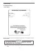
I. Specifications A. Nameplate Rating 1. KMS-1400MLH HOSHIZAKI ICE MAKER MODEL NUMBER SERIAL NUMBER AC SUPPLY VOLTAGE PUMP OTHER DESIGN PRESSURE REFRIGERANT KMS-1400MLH 115-120V/60/1 120V 1.2FLA 60W 115V 0.8A HI-467PSI LO-230PSI R-404A NOT INTENDED FOR OUTDOOR USE! WARNING: RISK OF ELECTRICAL SHOCK, WHICH CAN CAUSE INJURY OR DEATH. DISCONNECT ALL REMOTE ELECTRICAL POWER SUPPLIES BEFORE SERVICING UNIT. Hoshizaki America, Inc. Peachtree City, GA www.hoshizaki.
2. Condensing Unit Model SRK-14H MODEL NUMBER SERIAL NUMBER AC SUPPLY VOLTAGE SRK-14H 208-230/60/1 (3 WIRE WITH NEUTRAL FOR 115V) 230V 10.3RLA 54.0LRA COMPRESSOR FAN 115V 2.6FLA (total) 126W OTHER 115V 0.4A MAXIMUM FUSE SIZE 20 AMPS MAX. HACR BREAKER(USA ONLY) 20 AMPS MAX. CIRC. BREAKER (CANADA ONLY) 20 AMPS MINIMUM CIRCUIT AMPACITY 20 AMPS DESIGN PRESSURE HI-467PSI LO-230PSI REFRIGERANT R-404A 16LBS. 5oz.
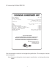
3. Condensing Unit Model SRK-14H3 MODEL NUMBER SERIAL NUMBER AC SUPPLY VOLTAGE SRK-14H3 208-230/60/3 COMPRESSOR 230V 7.5RLA 65.5LRA FAN 115V 2.6FLA (total) 126W OTHER 115V 0.4A MAXIMUM FUSE SIZE 20 AMPS MAX. HACR BREAKER(USA ONLY) 20 AMPS MAX. CIRC. BREAKER (CANADA ONLY) 20 AMPS MINIMUM CIRCUIT AMPACITY 20 AMPS DESIGN PRESSURE HI-467PSI LO-230PSI REFRIGERANT R-404A 16LBS. 5oz.
B. Dimensions/Connections Unit: mm [inches] 1.
Note: Legs are included with condensing unit. Leg height is 380 mm (14.96 in.). Unit: mm [inches] 2.
II. Installation and Operating Instructions IMPORTANT 1. Install in accordance with all applicable national, state, and local regulations. 2. Remove the shipping carton, tape, and packing material. If any are left in the units, they will not work properly. 3. Ensure all components, fasteners, and thumbscrews are securely in place after installation. A. Location 1. Icemaker CAUTION 1. This icemaker is not intended for outdoor use.
2. Condensing Unit IMPORTANT This condensing unit is intended for outdoor use. Normal operating ambient temperature should be within -20°F to +122°F (-29°C to 50°C). Operation of the unit, for extended periods, outside of these normal temperature ranges may affect icemaker performance. The icemaker must be coupled with the appropriate condensing unit as listed below.
B. Checks Before Installation IMPORTANT 1. Install in accordance with all applicable national, state, and local regulations. 2. Remove the shipping carton, tape, and packing material. If any are left in the icemaker or condensing unit, it will not work properly. 3. Ensure all components, fasteners, and thumbscrews are securely in place after installation. 1. Icemaker 1) Remove the panels to prevent damage when installing the icemaker. (See "II.C. How to Remove Panels.
C. How to Remove Panels 1. Icemaker • Front Panel: Remove the screw. Lift up and towards you. • Top Panel: Lift off. • Side Panel (R): Remove the screw. Slide forward slightly and lift off. • Insulation Panel: Remove the thumbscrews. Lift up slightly and pull towards you. Top Panel Side Panel (R) Insulation Panel Front Panel Icemaker Fig. 2 2. Condensing Unit • Top Panel: Remove the screws and lift off. • Front Panel: Remove the screws and lift off.
D. Installation of the Icemaker CAUTION 1. Power supply and ground wire to the icemaker are supplied from the condensing unit. For details, see section "II.F. Electrical Connection." 2. Before operating the icemaker, the bin control must be installed correctly. Failure to properly install the bin control could result in ice backup and unit damage. 1. Setup 1) If mounting the unit on top of a dispenser unit, follow the dispenser unit's setup procedure.
2) Disconnect the pump suction hose from the plastic pipe. 3) Disconnect the drain pipe from the plastic pipe. Pump Suction Hose Drain Pipe 2 3 4) Disconnect the float connection hose from the plastic pipe. 5) Disconnect the tank drain hose from the tank. Although the tank can be removed at this point, do not remove it yet because the bin control is taped to the tank. Float Connection Hose Tank Drain Hose 4 5 CAUTION The bin control lead is routed through the back of the icemaker.
10) Slightly loosen the outer 2 thumbscrews. 11) Slide the thumbscrews into the slots on the bin control bracket. The bin control bracket is located on the back wall of the icemaker. Thumbscrews Slots 11 10 CAUTION If a gap is left between the bin control and the wall of the dispenser, ice may get between them and damage the bin control. Therefore, make sure there is no gap. 12) Make sure the bin control is flush with the dispenser unit/storage bin wall, then tighten the 2 thumbscrews.
E. Installation of the Condensing Unit CAUTION 1. Failure to install the equipment within these guidelines may adversely affect performance, component life, and warranty coverage 2. Power supply and ground wire to the icemaker are supplied from the condensing unit. For details, see section "II.F. Electrical Connection." 1. Setup 1) Secure the condensing unit to the stand with sixteen M8×16 mm hexagon bolts and M8 nuts as shown in the illustration. See Fig. 4. 2) The legs have eight mounting holes.
Factory Line Set Installation 1) Route the factory line set (5/8" OD suction line and a 1/2" OD liquid line) from the condensing unit to the icemaker. Factory fabricated line sets are precharged and do not need to be evacuated. Note: Care should be taken that the icemaker, line set, and remote condenser unit contain the same type of refrigerant prior to making connections. Mixing of refrigerants will result in improper operation and possible damage to the refrigeration system.
F. Electrical Connection WARNING 1. Electrical connections must be made in accordance with the instructions on the "WARNING" tag, provided with the pig tail leads in the condensing unit junction box. 2. Electrical connections must meet national, state, and local electrical code requirements. Failure to meet these code requirements could cause severe injury to individuals or extensive damage to equipment. 3. Be sure to install a proper ground to the condensing unit. 4.
2. Condensing Unit 1) Connect the wire harness wires to the appropriate terminals on the condensing unit's terminal board using the wiring label or Fig. 8 as a reference. Be sure to connect the ground wire (included in the wire harness). 2) Supply power from the electrical panel to the condensing unit. (This differs from KM style installations.) 3) Connect the wire leads in the power supply junction box to the power supplied from the disconnect or electrical panel. Connect a ground wire to the ground screw.
V V P P Wire Color Code: BK-black BR-brown GN-green P-pink V-violet W-white L2 HGV or Contactor L3 BR BR BK W GN Neutral W GN GND Legend: GND-ground HGV-hot gas valve CB-control board LLV-liquid line valve L2-single phase power supply L3-three phase power supply LLV BK SRK Condensing Unit GND V CB BR Fuse 10A BR GN V KMS Icemaker Unit (factory connected) Wire Harness Connections HGV P P LLV BK BK W Neutral W Fig.
G. Water Supply and Drain Connections See Fig. 9 IMPORTANT To prevent damage to the equipment, do not operate the icemaker when the water supply is off, or if the pressure is below 10 PSIG. Do not run the icemaker until the proper water pressure is reached. • The icemaker must be installed in accordance with applicable national, state, and local regulations. • A plumbing permit and services of a licensed plumber may be required in some areas. • Water supply inlet is 1/2" female pipe thread (FPT).
H.
I. Startup IMPORTANT 1. Electrical power must be on at the condensing unit for a minimum of 4 hours prior to startup to prevent compressor damage. 2. All parts are factory-adjusted. Improper adjustments may result in failure. 3. If the unit is turned off, wait for at least three minutes before restarting the icemaker to prevent damage to the compressor. 4. Do not operate the unit in the "WASH" position without water in the water tank. This will cause damage to the water pump seal.
III. Cleaning and Maintenance IMPORTANT Ensure all components, fasteners, and thumbscrews are securely in place after any cleaning or maintenance is done to the equipment. A. Cleaning and Sanitizing Instructions HOSHIZAKI recommends cleaning this unit at least once a year. More frequent cleaning, however, may be required in some existing water conditions. WARNING 1. To prevent injury to individuals and damage to the icemaker, do not use ammonia type cleaners. 2.
e. Reassemble the float switch. Replace the rubber boot and the float switch in their correct positions. Reconnect the vent tube. f. Replace the right-side panel in its correct position. 9) Remove the insulation panel by removing the thumbscrews, then pour the cleaning solution into the water tank. 10) Move the service switch to the "WASH" position. 11) Replace the insulation panel and the front panel in their correct positions. 12) Turn on the power supply to start the washing process.
2. Sanitizing Procedure - Following Cleaning Procedure 1) Dilute 2 fl. oz. (60 ml or 4 tbs) of a 5.25% sodium hypochlorite solution (chlorine bleach) with 4 gal. (15 l) of warm water. 2) Remove the insulation panel if it is in its normal position. 3) Pour the sanitizing solution into the water tank. 4) Move the service switch to the "WASH" position. 5) Replace the insulation panel and the front panel in their correct positions. 6) Turn on the power supply to start the sanitizing process.
C. Preparing the Icemaker for Long Storage CAUTION When shutting off the icemaker for an extended time, drain out all water from the water tank and remove the ice from the dispenser unit/storage bin. The dispenser unit/storage bin should be cleaned and dried. Drain the icemaker to prevent damage to the water supply line at sub-freezing temperatures, using air or carbon dioxide. Shut off the icemaker until the proper ambient temperature is resumed.
15) Move the control switch to the "OFF" position. 16) Disconnect the float switch vent hose from the drain hose tee. Move the service switch to the "DRAIN" position and the control switch to the "SERVICE" position. 17) From the tee on the drain hose, blow the drain water valve out using compressed air or carbon dioxide. 18) Move the service switch to the "CIRC" position and the control switch to the "OFF" position. 19) Reconnect the thermistor to the K3 connector on the control board.
HOSHIZAKI AMERICA, INC. 618 Hwy. 74 S., Peachtree City, GA 30269 USA TEL (770) 487-2331 FAX (770) 487-3360 www.hoshizaki.