Hoshizaki Hoshizaki America, Inc. Low-Profile Modular Crescent Cuber Models KML-250MAH, MWH KML-351MAH, MWH KML-451MAH, MWH KML-631MAH, MWH, MRH “A Superior Degree of Reliability” INSTRUCTION MANUAL www.hoshizaki.
WARNING Only qualified service technicians should install and service the appliance. To obtain the name and phone number of your local Hoshizaki Certified Service Representative, visit www.hoshizaki.com. No installation or service should be undertaken until the technician has thoroughly read this Instruction Manual. Likewise, the owner/manager should not proceed to operate the appliance until the installer has instructed them on its proper operation.
IMPORTANT This manual should be read carefully before the appliance is installed and operated. Read the warnings and guidelines contained in this manual carefully as they provide essential information for the continued safe use and maintenance of the appliance. Retain this manual for any further reference that may be necessary. CONTENTS Important Safety Information.................................................................................................. 4 I. Specifications..........................
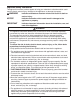
Important Safety Information Throughout this manual, notices appear to bring your attention to situations which could result in death, serious injury, damage to the appliance, or damage to property. WARNING Indicates a hazardous situation which could result in death or serious injury. NOTICE Indicates a situation which could result in damage to the appliance or property. IMPORTANT Indicates important information about the installation, use, and care of the appliance.
WARNING, continued • Children should be properly supervised around the appliance. • Do not climb, stand, or hang on the appliance or allow children or animals to do so. Serious injury could occur or the appliance could be damaged. • Do not use combustible spray or place volatile or flammable substances near the appliance. They might catch fire. • Keep the area around the appliance clean. Dirt, dust, or insects in the appliance could cause harm to individuals or damage to the appliance.
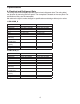
I. Specifications A. Electrical and Refrigerant Data The rating label and nameplate provide electrical and refrigerant data. The rating label can be seen by removing the front panel. The nameplate is located on the rear panel. For certification marks, see the nameplate. We reserve the right to make changes in specifications and design without prior notice. 1. KML-250M_H Model Number AC Supply Voltage Compressor Pump Fan Other Maximum Fuse Size Max. HACR Breaker (USA Only) Max.
3. KML-451M_H Model Number AC Supply Voltage Compressor Pump Fan Other Maximum Fuse Size Max. HACR Breaker (USA Only) Max. Circuit Breaker (Canada Only) Minimum Circuit Ampacity Design Pressure Refrigerant KML-451MAH 115/60/1 115-120V 7.9RLA 54.5LRA 120V 0.5FLA 23W 120V 0.85FLA 50W 115-120V 0.15A 20 AMPS 20 AMPS KML-451MWH 115/60/1 115-120V 9.0RLA 70LRA 120V 0.5FLA 23W --- --- --115-120V 0.15A 20 AMPS 20 AMPS 20 AMPS 20 AMPS 20 AMPS 20 AMPS HI-467PSI LO-230PSI 404A 1 LB. 8.7 OZ.
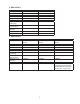
B. Dimensions/Connections Units: mm [in.] 1. Air-Cooled Models (MAH) Rear Side Model Shown: KML-451MAH KML-250MAH KML-351MAH KML-451MAH A 559 [22] B 515 [20-1/4] C 505 [19-7/8] KML-631MAH Model Shown: KML-451MAH 659 [26] 615 [24-1/4] 605 [23-7/8] Bottom Model Shown: KML-451MAH NOTICE • Allow 6" (15 cm) clearance at rear, sides, and top for proper air circulation and ease of maintenance and/or service should they be required.
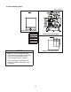
2. Water-Cooled Models (MWH) Units: mm [in.] Rear KML-250/351/451/MWH Side Model Shown: KML-451MWH A B C D E KML-250MWH KML-351MWH KML-451MWH 559 [22] 515 [20-1/4] 505 [19-7/8] 403 [15-7/8] 55 [2-1/8] KML-631MWH Model Shown: KML-451MWH 659 [26] 615 [24-1/4] 605 [23-7/8] 504 [19-7/8] - Rear KML-631MWH NOTICE • Allow 6" (15 cm) clearance at rear, sides, and top for proper air circulation and ease of maintenance and/or service should they be required.
3. Remote Models (MRH) Units: mm [in.] Rear Side Model Shown: KML-631MRH A B C D E F G KML-631MRH 659 [26] 615 [24-1/4] 605 [23-7/8] 448 [17-5/8] 41 [1-5/8] 63 [2-1/2] 75 [3] NOTICE Model Shown: KML-631MRH Bottom Model Shown: KML-631MRH • Allow 6" (15 cm) clearance at rear, sides, and top for proper air circulation and ease of maintenance and/or service should they be required. • The ice storage bin opening must match the bottom opening as in the illustration.
4. Remote Condenser Unit URC-9F (use with KML-631MRH) Units: mm [in.] NOTICE Allow 24" (61 cm) clearance at front and rear for proper air circulation and ease of maintenance and/or service should they be required.
II. Installation and Operating Instructions WARNING • The appliance must be installed in accordance with applicable national, state, and local codes and regulations. • Failure to install, operate, and maintain the appliance in accordance with this manual will adversely affect safety, performance, component life, and warranty coverage and may result in costly water damage. • CHOKING HAZARD: Ensure all components, fasteners, and thumbscrews are securely in place after installation.
• Check that the refrigerant lines do not rub or touch lines or other surfaces, and that the fan blade (if applicable) turns freely. • Check that the compressor is snug on all mounting pads. • The icemaker can be installed on a dispenser unit or ice storage bin. The ice storage bins listed below are recommended. Model Number Bin Width Recommended Hoshizaki Ice Storage Bin KML-250M_H 30" or Wider B-500 Series KML-351M_H KML-451M_H KML-631M_H For further options, contact your local Hoshizaki distributor.
D. Setup 1. Dispenser Unit/Ice Storage Bin and Icemaker Setup WARNING The installer must ensure the dispenser unit/ice storage bin is compatible with the icemaker, and the dispenser unit/ice storage bin and icemaker are properly attached and secured. 1a) Dispenser Unit: Follow the dispenser unit's setup procedure. 1b) Ice Storage Bin: Unpack the ice storage bin and attach the 4 adjustable legs provided (bin accessory) to the bottom of the ice storage bin.
Intentionally Left Blank 15
E. Electrical Connection WARNING For All Models • Electrical connection must be hard-wired and must meet national, state, and local electrical code requirements. Failure to meet these code requirements could result in death, electric shock, serious injury, fire, or damage. • The icemaker requires an independent power supply of proper capacity. See the nameplate for electrical specifications.
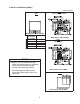
KML-250M_H KML-351M_H KML-451M_H KML-631M_H WARNING ELECTRICAL CONNECTION THIS UNIT MUST BE GROUNDED Failure to properly ground or wire this unit could result in death, serious injury, or severe damage to the icemaker. The white lead must be connected to the neutral conductor of the power source. See diagram below. 115-120/60/1 JUNCTION BOX 115-120V L N BROWN WHITE Based on 435005 4Axxxx-010 Fig.
F. Water Supply and Drain Connections See Figs. 4 through 8 WARNING Water supply and drain connections must be installed in accordance with applicable national, state, and local regulations. NOTICE • Normal operating water temperature should be within 45°F to 90°F (7°C to 32°C). Operation of the appliance, for extended periods, outside of this normal temperature range may affect appliance performance. • Water supply pressure must be a minimum of 10 PSIG and a maximum of 113 PSIG.
1. Icemaker Icemaker Water Supply Inlet 1/2" Female Pipe Thread (FPT) Minimum Icemaker Water Supply Line Size 1/4" Nominal ID Copper Water Tubing or Equivalent Icemaker Drain Outlet 3/4" Female Pipe Thread (FPT) Minimum Icemaker Drain Line Size 3/4" Nominal ID Hard Pipe or Equivalent • An icemaker water supply line shut-off valve and drain valve must be installed. • Be sure there is sufficient extra water supply line and drain line for the appliance to be pulled out for service.
2. Water-Cooled Condenser a) KML-250/351/451MWH (1) Connection to an Open Drain System Condenser Water Supply Inlet 1/2" Female Pipe Thread (FPT) Minimum Condenser Water Supply Line Size 1/4" Nominal ID Copper Water Tubing or Equivalent Condenser Drain Outlet 3/8" Female Pipe Thread (FPT) Minimum Condenser Drain Line Size 1/4" Nominal ID Hard Pipe or Equivalent • A condenser water supply line shut-off valve and drain valve must be installed.
(2) Connection to a Closed Loop System Condenser Water Supply Inlet 1/2" Female Pipe Thread (FPT) Minimum Condenser Water Supply Line Size 1/4" Nominal ID Copper Water Tubing or Equivalent Condenser Return Outlet 3/8" Female Pipe Thread (FPT) Minimum Condenser Return Line Size 1/4" Nominal ID Copper Water Tubing or Equivalent • Shut-off valves and drain valves must be installed at both the condenser water supply inlet and condenser return outlet. • Minimum water flow to the condenser is 4 GPM.
b) KML-631MWH (1) Connection to an Open Drain System Condenser Water Supply Inlet 1/2" Female Pipe Thread (FPT) Minimum Condenser Water Supply Line Size 1/4" Nominal ID Copper Water Tubing or Equivalent Condenser Drain Outlet 3/8" Female Pipe Thread (FPT) Minimum Condenser Drain Line Size 1/4" Nominal ID Hard Pipe or Equivalent • A condenser water supply line shut-off valve and drain valve must be installed. • In some areas, a back flow preventer may be required in the cooling water circuit.
(2) Connection to a Closed Loop System Condenser Water Supply Inlet 1/2" Female Pipe Thread (FPT) Minimum Condenser Water Supply Line Size 1/4" Nominal ID Copper Water Tubing or Equivalent Condenser Return Outlet 3/8" Female Pipe Thread (FPT) Minimum Condenser Return Line Size 1/4" Nominal ID Copper Water Tubing or Equivalent • Shut-off valves and drain valves must be installed at both the condenser water supply inlet and condenser return outlet. • Minimum water flow to the condenser is 4 GPM.
G. Installation of Remote Condenser Unit WARNING • Installation of remote condenser unit must be performed by properly trained and EPA-certified service personnel. • The remote condenser unit must be installed in accordance with applicable national, state, and local codes and regulations. • Failure to install the remote condenser unit within these guidelines may adversely affect safety, performance, component life, and warranty coverage.
2. Checks Before Installation 1) Remove the shipping carton, tape, and packing material. 2) Check that the refrigerant lines do not rub or touch lines or other surfaces, and that the fan blade moves freely. 3. Setup 1) Assemble 2 sets of legs using the legs, bolts, and nuts provided. See Fig. 11. 2) Position 1 of the plates provided between a set of legs and the remote condenser unit, then secure the legs to the remote condenser unit with the bolts and nuts provided.
5. Line Set Installation Precharged factory line sets, available as optional equipment from Hoshizaki America, are recommended. For details, see "II.G.5.a) Factory Line Set Installation." Field fabricated line sets are allowed. For details, see "II.G.5.b) Field Fabricated Line Set Installation." a) Factory Line Set Installation 1) Route the factory line set (see "II.G.4 Line Set Size and Refrigerant Charge" for details) from the remote condenser unit to the icemaker.
3) Evacuate through the Schrader access ports on the Parker quick connect couplings and charge with R-404A refrigerant vapor to a pressure of 15 to 30 PSIG. Go to step 2 in "II.G.5.a) Factory Line Set Installation." b) Field Fabricated Line Set Installation 1) Route the copper tube liquid line and copper tube discharge line (see "II.G.4 Line Set Size and Refrigerant Charge" for details) from the remote condenser unit to the icemaker.
Remote Condenser Unit Icemaker Male Fitting Female Coupling Fig. 12 Discharge Line (Insulated) See "II.G.4 Line Set Size and Refrigerant Charge" for details. Liquid Line (Insulated) See "II.G.4 Line Set Size and Refrigerant Charge" for details. Service Loop DO NOT USE THREAD SEALANT Male Fitting Brush Fig. 13 Threads Diaphragm Apply POE Oil or Parker Super O Lube to Entire Male Fitting O-Ring Reference Line Fig.
6. Electrical Connection WARNING • Electrical connection must meet national, state, and local electrical code requirements. Failure to meet these code requirements could result in death, electric shock, serious injury, fire, or damage. • To reduce the risk of electric shock, make all remote condenser unit connections before connecting the icemaker power supply. • THE REMOTE CONDENSER UNIT MUST BE GROUNDED.
3) Install a ground wire from the icemaker fan motor junction box to the remote condenser unit junction box. Use wire of an appropriate gage and outdoor rating. 4) Install line and neutral wires from the fan motor leads in the icemaker fan motor junction box to the leads in the remote condenser unit junction box. Use wire of an appropriate gage and outdoor rating. 5) Replace the junction box covers and the louver panel in their correct positions. 7.
H. Final Checklist WARNING CHOKING HAZARD: Ensure all components, fasteners, and thumbscrews are securely in place after installation. Make sure that none have fallen into the dispenser unit/ice storage bin.
I. Startup WARNING All parts are factory-adjusted. Improper adjustments may adversely affect safety, performance, component life, and warranty coverage. NOTICE • If the icemaker is turned off, wait for at least 3 minutes before restarting the icemaker to prevent damage to the compressor. • To prevent damage to the water pump, do not leave the control switch in the "SERVICE" position for extended periods when the water tank is empty.
III. Maintenance The appliance must be maintained in accordance with the instruction manual and labels provided. Consult with your local Hoshizaki Certified Service Representative about maintenance service. WARNING • Only qualified service technicians should service the appliance. • To reduce the risk of electric shock, do not touch the control switch or service switch with damp hands. • Move the control switch to the "OFF" position and turn off the power supply before servicing.
B. Cleaning and Sanitizing Instructions The icemaker must be cleaned and sanitized at least once a year. More frequent cleaning and sanitizing may be required in some water conditions. WARNING • To prevent injury to individuals and damage to the icemaker, do not use ammonia type cleaners. • Carefully follow any instructions provided with the bottles of cleaning and sanitizing solution.
9) Pour the cleaning solution into the water tank. 10) Move the service switch to the "WASH" position. 11) Replace the front insulation panel and the front panel in their correct positions. 12) Turn on the power supply to start the washing process. 13) Turn off the power supply after 30 minutes. 14) Remove the front panel. 15) Move the service switch to the "DRAIN" position. 16) Replace the front panel in its correct position, then turn on the power supply for 2 minutes.
4) Move the service switch to the "WASH" position. 5) Replace the front insulation panel and the front panel in their correct positions. 6) Turn on the power supply to start the sanitizing process. 7) Turn off the power supply after 15 minutes. 8) Remove the front panel. 9) Move the service switch to the "DRAIN" position. 10) Replace the front panel in its correct position, then turn on the power supply for 2 minutes. 11) Turn off the power supply. 12) Remove the front panel.
IV. Preparing the Icemaker for Periods of Non-Use NOTICE • When storing the icemaker for an extended time or in sub-freezing temperatures, follow the instructions below to prevent damage. • To prevent damage to the water pump, do not leave the control switch in the "SERVICE" position for extended periods when the water tank is empty. When the icemaker is not used for two or three days under normal conditions, it is sufficient to move the control switch to the "OFF" position.
3) Open the condenser water supply line drain valve. If connected to a closed loop system, also open the condenser return line drain valve. 4) Attach a compressed air or carbon dioxide supply to the condenser water supply line drain valve. 5) Open the water regulating valve by using a screwdriver to pry up on the spring retainer underneath the spring. While holding the valve open, blow out the condenser using the compressed air or carbon dioxide supply until water stops coming out.
V. Disposal The appliance contains refrigerant and must be disposed of in accordance with applicable national, state, and local codes and regulations. Refrigerant must be recovered by properly certified service personnel.
HOSHIZAKI AMERICA, INC. 618 Hwy. 74 S., Peachtree City, GA 30269 USA TEL (770) 487-2331 FAX (770) 487-3360 www.hoshizaki.