Hoshizaki Hoshizaki America, Inc. Modular Crescent Cuber Serenity Series Model KMS-1400MLH Including Condensing Unit Model SRK-14H/3 “A Superior Degree of Reliability” SERVICE MANUAL www.hoshizaki.
IMPORTANT Only qualified service technicians should attempt to install, service, or maintain this icemaker. No service or maintenance should be undertaken until the technician has thoroughly read this Service Manual. Failure to service and maintain the equipment in accordance with this manual may adversely affect safety, performance, and warranty coverage. HOSHIZAKI provides this manual primarily to assist qualified service technicians in the service and maintenance of the icemaker.
IMPORTANT This manual should be read carefully before the icemaker is serviced or maintenance operations are performed. Only qualified service technicians should install, service, and maintain the icemaker. Read the warnings contained in this booklet carefully as they give important information regarding safety. Please retain this booklet for any further reference that may be necessary. CONTENTS I. Specifications...............................................................................................
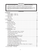
E. Float Switch................................................................................................................. 23 1. Explanation of Operation........................................................................................ 23 2. Cleaning................................................................................................................. 23 3. Float Switch Check Procedure .............................................................................. 23 F. Bin Control.....
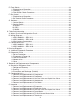
VI. Cleaning and Maintenance ............................................................................................ 52 A. Cleaning and Sanitizing Instructions............................................................................ 52 1. Cleaning Procedure................................................................................................ 52 2. Sanitizing Procedure - Following Cleaning Procedure........................................... 54 B. Maintenance................................
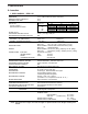
I. Specifications SPECIFICATION DATA NO. 08A001 ISSUED: January 22,2008 A. Icemaker REVISED: ITEM: HOSHIZAKI MODULAR CRESCENT CUBER WITH REMOTE COMPRESSOR/CONDENSER UNIT MODEL: KMS-1400MLH – with SRK-14H 1. KMS-1400MLH SRK-14H AC SUPPLY VOLTAGE AMPERAGE MINIMUM CIRCUIT AMPACITY MAXIMUM FUSE SIZE APPROXIMATE ICE PRODUCTION PER 24 HR. lbs./day ( kg/day ) Reference without *marks 208-230/60/1 ( 3 wire with neutral for 115V ) 15 A ( 5 Min. Freeze AT 104°F / WT 80°F ) 20 A 20 A Ambient WATER TEMP.
2. KMS-1400MLH – SRK-14H3 Intentionally Left Blank Note: We reserve the right to make changes in specifications and design without prior notice.
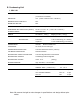
B. Condensing Unit 1. SRK-14H AC SUPPLY VOLTAGE 208-230/60/1 ( 3 wire with neutral for 115V ) ( Connection to icemaker ) AMPERAGE 15 A ( 5 Min. Freeze AT 104°F / WT 80°F ) MINIMUM CIRCUIT AMPACITY 20 A MAXIMUM FUSE SIZE 20 A EXTERIOR DIMENSIONS ( WxDxH ) 50" x 17" x 28" ( 1270 x 432 x 711 mm ) DIMENSIONS INCLUDING LEGS ( WxDxH ) 52-3/8" x 19-1/2" x 43" ( 1330 x 495 x 1092 mm ) EXTERIOR FINISH Galvanized steel WEIGHT Net 230 lbs.
2. SRK-14H3 Intentionally Left Blank Note: We reserve the right to make changes in specifications and design without prior notice.
II. General Information A. Construction 1.
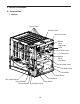
2. Condensing Unit Condenser Liquid Line Valve Headmaster (C.P.
B. Sequence of Operation The steps in the sequence are as outlined below. When power is supplied, the red POWER OK LED and the green BC CLOSED LED on the control board come on (If the yellow BC OPEN LED is on, the unit will not start. In this case clear ice away from the bin control actuator in the bin area). A 5-second delay occurs at startup. Note that the order of the green sequence LEDs from the outer edge of the board is 1, 4, 3, 2. 1. One Minute Fill Cycle LED 4 is on.
5. Normal Harvest Cycle LEDs 1, 4 and 2 are on. Comp, FMR and HGVs remain energized. HWV and X1 relay energize, PM stops. As the evaporator warms, the thermistor reaches 48°F (9°C). The control board then receives the thermistor's 3.9 kΩ signal and starts the harvest timer. When the harvest timer completes its count down, the harvest cycle is complete. The minimum total time allowed by the board for a complete harvest cycle is 2 minutes.
LF/S closed Thermistor in control 4. Pump-Out Cycle Freeze cycle operation turned over to LF/S PM de-energizes 2 sec. , energizes for 10 sec. Comp continues FMR continues DWV energized HGV energized LLV de-energized Power is supplied to the pump and drain valve. This drains the water tank. Power is supplied to the pump only. This operation can be used to circulate cleaner and sanitizer for extended periods of time over the outside surface of the evaporator.
C. Control Board • A HOSHIZAKI exclusive solid-state control is employed in the KMS-1400MLH Modular Crescent Cuber. • All models are pretested and factory-adjusted. CAUTION 1. Fragile, handle very carefully. 2. A control board contains integrated circuits, which are susceptible to failure due to static discharge. It is especially important to touch the metal part of the unit when handling or replacing the board. 3.
1.
2. Features a) Maximum Water Supply Period – 6 minutes The harvest water valve will be open during harvest for 6 minutes or the length of harvest minus 50 seconds, whichever is shorter. b) Harvest Backup Timer and Freeze Timer The harvest backup timer shuts down the icemaker if, for two cycles in a row, the harvest cycle takes more than 20 minutes to complete. The control board will signal this problem using 2 beeps every 3 seconds.
f) LED Lights and Audible Alarm Safeties The control board includes LED indicator lights, audible alarm safeties, and an output test. The red LED indicates control voltage and will remain on unless a control voltage problem occurs. At startup a 5-second delay occurs while the board conducts an internal timer check. A beep occurs when the control switch is moved to the "ICE" position. The green LEDs 1 through 4 energize and sequence from initial startup as listed in the table below.
3. Controls and Adjustments a) Default Dip Switch Settings The dip switches are factory-adjusted to the following positions: S4 Dip Switch Dip Switch No. 1 KMS-1400MLH 2 3 4 OFF OFF OFF ON 5 6 ON ON 7 8 9 10 ON OFF OFF ON S5 Dip Switch (Do Not Adjust) Dip Switch No.
c) Pump-Out Timer (S4 dip switch 3 & 4) During cycles when a pump out is called for, the pump motor drains the water tank for the time determined by the pump-out timer (T1). The pump-out timer's harvest timer (T2) acts in place of the harvest timer (S4 dip switch 1 & 2) during cycles with a pump out. The pump-out timer is factory-adjusted, and no adjustment is required. Dip Switch Setting Time (seconds) No. 3 No.
f) Freeze Timer (S4 dip switch 9 & 10) CAUTION Adjust to proper specification, or the unit may not operate correctly. The freeze timer setting determines the maximum allowed freeze time to prevent possible freeze-up issues. Upon termination of freeze timer, the control board initiates the harvest cycle. After 2 consecutive timer terminations, the control board shuts the machine down. In this case, see "IV.B.3. Low Ice Production" for possible solutions.
5. Control Board Replacement The dip switches should be adjusted to the factory default settings as outlined in this manual. S4 dip switch #8 must remain off. D. Harvest Control – Thermistor A thermistor (semiconductor) is used for a harvest control sensor. The resistance varies depending on the suction line temperatures. The thermistor detects the temperature of the evaporator outlet to start the harvest timer. No adjustment is required.
E. Float Switch 1. Explanation of Operation The float operates 2 switches within the float switch. The lower switch (black and blue wires) is used for low water safety protection, initiating the freeze cycle refill and terminating the freeze cycle. The upper switch (black and red wires) is used to terminate the freeze cycle refill only. Refill will last until the upper float switch closes or the 1 minute countdown timer ends, whichever comes first. 2.
Black - Common Blue - Lower Switch Red - Upper Switch Mechanical Lock Housing Upper Switch Lower Switch Retainer Clip Float Fig.
F. Bin Control This machine uses a lever-actuated proximity switch (mechanical bin control) to control the ice level in the storage bin. No adjustment is required. 1. Explanation of Operation The bin control is connected to the red K4 connector on the control board. When the bin control is calling for ice (proximity switch closed; green LED, BC CLOSED, on), the control board continues icemaking operations.
G. Switches Two control switches are used to control operation in KMS Series Modular Crescent Cubers. These switches are referred to as the "control switch" and the "service switch" and are located on the control box. 1. Control Switch The control switch has three positions: "OFF" for power off; "ICE" for icemaking, and "SERVICE" to activate the service switch. 2.
Water Tank Fill Water Valve Evaporator Pump Motor Spray Tube Drain Fan Compressor High Pressure Switch Fusible Plug Strainer Hot Gas Valve Access Valve Check Valve Headmaster (C.P.
** * Pressure Switch Cut-out 412±21 0 PSIG Cut-in 327±21 PSIG 1. KMS-1400MLH – SRK-14H Transformer Output 10.5V at 115V ** Thermostat Switch Cut-out 266°F±9°F Cut-in 239°F±9°F B.
** * Pressure Switch Cut-out 412±21 0 PSIG Cut-in 327±21 PSIG Transformer Output 10.5V at 115V ** Thermostat Switch Cut-out 266°F±9°F Cut-in 239°F±9°F 2.
V V P P Wire Color Code: BK-black BR-brown GN-green P-pink V-violet W-white L2 HGV or Contactor L3 BR BR BK W GN Neutral W GN GND Legend: GND-ground HGV-hot gas valve CB-control board LLV-liquid line valve L2-single phase power supply L3-three phase power supply LLV BK SRK Condensing Unit GND V CB BR Fuse 10A BR GN V KMS Icemaker Unit (factory connected) Wire Harness Connections HGV P P LLV BK BK W Neutral W 3.
C. Performance Data DATA 08A001 1.PERFORMANCE KMS-1400MLH – NO. SRK-14H ISSUED: January 22,2008 REVISED: ITEM: HOSHIZAKI MODULAR CRESCENT CUBER WITH REMOTE COMPRESSOR/CONDENSER UNIT MODEL: KMS-1400MLH with SRK-14H APPROXIMATE ICE WATER TEMP. (ºF/ºC) AMBIENT TEMP. PRODUCTION PER 24 HR. (ºF/ºC) 50/10 70/21 90/32 70/21 582 1242 564 1164 528 1284 lbs./day kg./day APPROXIMATE ELECTRIC CONSUMPTION watts APPROXIMATE WATER CONSUMPTION PER 24 HR. 3 gal./day m /day FREEZING CYCLE TIME min.
2. KMS-1400MLH – SRK-14H3 Intentionally Left Blank Note: 1. Pressure data is recorded at 5 minutes into freezing cycle. The data not in bold should be used for reference only. 2. We reserve the right to make changes in specifications and design without prior notice.
IV. Service Diagnosis A. 10-Minute Diagnostic Procedure The 10-minute check out procedure is basically a sequence check which can be used at unit start-up or for system diagnosis. Using this check out procedure will allow you to diagnose electrical system and component failures in approximately 10 minutes under normal operating conditions of 70°F (21°C) or warmer air and 50°F (10°C) or warmer water temperatures.
5) Freeze Cycle – LED 1 is on. The compressor, fan motors and pump motor remain energized. The liquid line valves energize and the hot gas valves de-energize (also de-energizing the X1 relay). The lower float switch activates (open) 2 times during the course of a freeze cycle; the first is for refill, the second is for freeze termination. After the second lower float switch activation, the control board terminates freeze and initiates harvest.
6) Pump-Out Cycle – The 1st pump out occurs after the 11th freeze cycle and every 10th cycle thereafter. LEDs 1, 3, 2 are on. The compressor and fan motors remain energized. The drain water valve, hot gas valves and X1 relay energize, the liquid line valves de-energize. The pump motor stops for 2 seconds then restarts for 10 seconds (pump out frequency can be adjusted on S4 dip switches 5 and 6).
B. Diagnostic Charts 1. No Ice Production Problem Possible Cause [1] The icemaker will not a) Power Supply start. (Condensing Unit) b) Water Supply c) High Pressure Control Remedy 1. Off, blown fuse, or tripped breaker. 2. Loose connections. 1. Turn on, replace, or reset. 3. Bad contacts. 3. Check for continuity and replace. 4. Not within specifications. 4. Refer to nameplate and correct. 1. Water supply off or pressure too low. 1. Open contacts. 1. Check and get recommended pressure. 1.
Problem Possible Cause Remedy [1] The icemaker will not l) Fill Water Valve start. (continuted) [2] Water continues to be supplied, and the icemaker will not start. [3] Compressor will not start or stops operating. 1. Mesh filter or orifice clogged. 1. Clean. 2. Coil winding opened. 2. Replace. 3. Wiring to water valve. 3. Check for loose connection or open, and replace. 1. Defective. 1. See "II.C.4. Control Board m) Control Board Check Procedure". 1. See "II.C.2.
Problem Possible Cause [4] Water continues to a) Fill or Harvest Water be supplied in freeze Valve cycle (outside of b) Control Board refill). [5] No water comes from a) Water Supply Line spray tubes. Water pump will not start, or freeze cycle time is b) Fill or Harvest Water too short. Valve c) Water System d) Pump Motor Remedy 1. Diaphragm does not close. 1. Defective. 1. Check for water leaks with icemaker off. 1. See "II.C.4. Control Board Check Procedure". 1. Water pressure too 1.
2. Evaporator is Frozen Up Problem Possible Cause [1]Freeze cycle time is too long. a) Float Switch 1. Check and replace. 2. Float does not move freely. 2. Clean or replace. b) Fill or Harvest Water Valve 1. Diaphragm does not close. 1. Check for water leaks. c) Control Board 1. Defective. 1. See "II.C.4. Control Board Check Procedure". 1. Scaled up. 1. Clean. 1. Water pressure too low. 1. Check and get recommended pressure. 1. Dirty/restricted. 1. Replace filter. 1.
3. Low Ice Production Problem Possible Cause Remedy [1] Freeze cycle time is long. a) See chart 1.[3]. Also check dirty condenser coil, ambient temperature and refrigerant charge. b) See chart 2.[1] and check float switch, water valves and control board. [2] Harvest cycle time is a) See chart 2.[2] and check evaporator, water supply line, harvest water valve, long. ambient and/or water temperature, liquid line valve, thermistor, and control board. 4.
V. Removal and Replacement of Components IMPORTANT 1.Ensure all components, fasteners, and thumbscrews are securely in place after the equipment is serviced. 2. The Polyol Ester (POE) oils used in R-404A units can absorb moisture quickly. Therefore it is important to prevent moisture from entering the system when replacing or servicing parts. 3. Always install a new drier every time the sealed refrigeration system is opened. Do not replace the drier until after all other repair or replacement has been made.
2. Brazing. WARNING 1. Refrigerant R-404A itself is not flammable at atmospheric pressure and temperatures up to 176°F (80°C). 2. Refrigerant R-404A itself is not explosive or poisonous. However, when exposed to high temperatures (open flames), R-404A can be decomposed to form hydrofluoric acid and carbonyl fluoride both of which are hazardous. 3. Always recover the refrigerant and store it in an approved container. Do not discharge the refrigerant into the atmosphere. 4.
5) Disconnect the vacuum pump and attach a refrigerant service cylinder to the high‑side line. Remember to loosen the connection and purge the air from the hose. For the required refrigerant charge, see the rating label inside the front panel on the icemaker or on the nameplate on the condensing unit. Hoshizaki recommends only virgin refrigerant or reclaimed refrigerant which meets ARI Standard No. 700-88 be used. 6) A liquid charge is recommended for charging an R-404A system.
11) Remove the plugs from the suction, discharge, and process pipes. 12) Braze all fittings while purging with nitrogen gas flowing at a pressure of 3 to 4 PSIG. 13) Use an electronic leak detector or soap bubbles to check for leaks. Add a trace of refrigerant to the system (if using an electronic leak detector), and then raise the pressure using nitrogen gas (140 PSIG). DO NOT use R-404A as a mixture with pressurized air for leak testing. 14) Evacuate the system and charge it with refrigerant.
3. Removal and Replacement of Hot Gas Valve and Liquid Line Valve CAUTION 1. The condensing unit has 1 hot gas valve and 1 liquid line valve. Both valves have a strainer prior to the valve body. It is advisable to change the strainer when replacing the hot gas or liquid line valve. 2. Always use a copper tube of the same diameter and length when replacing the hot gas and liquid lines; otherwise performance may be reduced. 3. Always install a new drier every time the sealed refrigeration system is opened.
4. Removal and Replacement of Headmaster (Condensing Pressure Regulator ‑ C.P. Regulator) IMPORTANT Always install a new drier every time the sealed refrigeration system is opened. Do not replace the drier until after all other repair or replacement has been made. Install the new drier with the arrow on the drier in the direction of the refrigerant flow. 1) Turn off the power supply. 2) Remove the panels. 3) Recover the refrigerant and store it in an approved container.
5) Install the new fan motor and replace the removed parts in the reverse order of which they were removed. 6) Replace the panels in their correct positions. 7) Turn on the power supply. C. Icemaker IMPORTANT Always install a new drier every time the sealed refrigeration system is opened. Do not replace the drier until after all other repair or replacement has been made. Install the new drier with the arrow on the drier in the direction of the refrigerant flow.
2. Removal and Replacement of Expansion Valve IMPORTANT 1. Sometimes moisture in the refrigerant circuit exceeds the drier capacity and freezes up at the expansion valve. Always install a new drier every time the sealed refrigeration system is opened. Install the new drier with the arrow on the drier in the direction of the refrigerant flow. 2. It is advisable to change out both expansion valves when replacing an expansion valve. 3.
3. Removal and Replacement of Hot Gas Valve and Liquid Line Valve CAUTION 1. The icemaker unit has 1 hot gas valve and 1 liquid line valve. The hot gas valve has a strainer prior to the valve body. It is advisable to change the strainer and check valves when replacing the hot gas valve. 2. Always use a copper tube of the same diameter and length when replacing the hot gas and liquid lines; otherwise performance may be reduced. 3.
4. Removal and Replacement of Pump Motor 1) Turn off the power supply. 2) Remove the panels. 3) Drain the water tank by removing the insulation panel, front frame and suction hose. (See Fig. 3.) Suction Hose 4) Disconnect the pump suction and discharge hoses. Front Frame Thumbscrew 5) Unplug the water pump connector. Fig. 3 6) Remove the screws and pump motor bracket. 7) Remove the pump housing and check the impeller. 8) If the impeller is defective, install a new impeller.
6. Removal and Replacement of Thermistor CAUTION 1. Fragile, handle very carefully. 2. Always use a recommended sealant (high thermal conductive type), Model KE4560RTV manufactured by SHINETSU SILICONE, Part Code 60Y000-11, or Part Code 4A0683-01 equivalent. 3. Always use a recommended foam insulation (Non-absorbent Type) or equivalent. 4. Do not shorten or cut the thermistor leads when installing. Thermistor Lead 1) Turn off the power supply. Cable Tie 2) Remove the panels.
VI. Cleaning and Maintenance IMPORTANT Ensure all components, fasteners, and thumbscrews are securely in place after any cleaning or maintenance is done to the equipment. A. Cleaning and Sanitizing Instructions HOSHIZAKI recommends cleaning this unit at least once a year. More frequent cleaning, however, may be required in some existing water conditions. WARNING 1. To prevent injury to individuals and damage to the icemaker, do not use ammonia type cleaners. 2.
e. Reassemble the float switch. Replace the rubber boot and the float switch in their correct positions. Reconnect the vent tube. f. Replace the right-side panel in its correct position. 9) Remove the insulation panel by removing the thumbscrews, then pour the cleaning solution into the water tank. 10) Move the service switch to the "WASH" position. 11) Replace the insulation panel and the front panel in their correct positions. 12) Turn on the power supply to start the washing process.
2. Sanitizing Procedure - Following Cleaning Procedure 1) Dilute 2 fl. oz. (60 ml or 4 tbs) of a 5.25% sodium hypochlorite solution (chlorine bleach) with 4 gal. (15 l) of warm water. 2) Remove the insulation panel if it is in its normal position. 3) Pour the sanitizing solution into the water tank. 4) Move the service switch to the "WASH" position. 5) Replace the insulation panel and the front panel in their correct positions. 6) Turn on the power supply to start the sanitizing process.
C. Preparing the Icemaker for Long Storage CAUTION When shutting off the icemaker for an extended time, drain out all water from the water tank and remove the ice from the dispenser unit/storage bin. The dispenser unit/storage bin should be cleaned and dried. Drain the icemaker to prevent damage to the water supply line at sub-freezing temperatures, using air or carbon dioxide. Shut off the icemaker until the proper ambient temperature is resumed.
15) Move the control switch to the "OFF" position. 16) Disconnect the float switch vent hose from the drain hose tee. Move the service switch to the "DRAIN" position and the control switch to the "SERVICE" position. 17) From the tee on the drain hose, blow the drain water valve out using compressed air or carbon dioxide. 18) Move the service switch to the "CIRC" position and the control switch to the "OFF" position. 19) Reconnect the thermistor to the K3 connector on the control board.