Glass Door Merchandiser Model RM-26 Number: RM-26 Issued: 02-22-2017 Revised: 02-22-2017 RM-26
RM-26
TABLE OF CONTENTS Page UNIT FEATURES 4 CROSS SECTION VIEWS 5 EXPLODED VIEW 6, 7 REFRIGERATION SYSTEM 8, 9 CONDENSING UNIT ASSEMBLY AND ITS COMPONENTS 10, 11 SWING DOOR ASSEMBLY AND ITS COMPONENTS 12, 13 INTERIOR LIGHTING SYSTEM 14, 15 SIGN AND FRONT GRILL ASSEMBLY 16, 17 115V./60Hz.
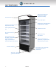
UNIT FEATURES Energy saving electronic thermostat with digital temperature reading Illuminated sign Heavy duty hinges Double-pane Low-E glass door for high ambient condition Forced-air evaporator for quick temperature pull down Interior lighting LED lamp strip Durable PVC frame NSF compliant interior cabinet Reinforced heavy duty shelves Strong body with 1 3/4” thick walls, injected with polyurethane foam using cyclopenthane as the blowing agent earth friendly Exterior cabinet ma
CROSS SECTION VIEWS RM-26 (DIMENSIONS: INCHES [MM]) 30 [762] 27 1/2 [699] 26 1/2 [673] 1 3/4 [44] 25 3/4 [654] 31 9/32 [795] 1 3/4 [44] SECTION B-B SCALE 3/64 TOP VIEW 29 21/32 [753] 30 [762] 23 1/2 [597] 29 7/8 [759] 9 [229] 54 5/8 [1386] PUERTA A B B 5/8 [16] 77 1/4 [1962] 61 7/8 [1572] 78 [1980] 78 17/32 [1994] 21 1/8 [537] A 12 15/32 [317] SECTION A-A SCALE 3/64 SIDE VIEW FRONT VIEW RM-26 5
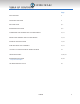
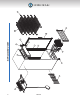
RM-26 1 14 11 5 2 7 4 6 13 EXPLODED VIEW 12 3 8 10 9
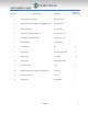
EXPLODED VIEW Quantity Item No. 1 Description Part No.
REFRIGERATION SYSTEM 1 6 7 2 8 11 5 10 4 9 3 8 RM-26
REFRIGERATION SYSTEM Quantity Item No. Description Part No.
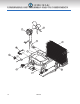
CONDENSING UNIT ASSEMBLY AND ITS COMPONENTS 8 7 9 6 5 11 3 2 4 12 10 1 10 RM-26
CONDENSING UNIT ASSEMBLY AND ITS COMPONENTS Quantity Item No. Description Part No.
SWING DOOR ASSEMBLY AND ITS COMPONENTS 6 3 2 1 5 7 4 12 RM-26
SWING DOOR ASSEMBLY AND ITS COMPONENTS Quantity Item No. Description Part No.
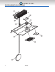
INTERIOR LIGHTING SYSTEM 3 4 5 2 6 1 2 14 RM-26
INTERIOR LIGHTING SYSTEM Quantity Item No. Description Part No. per cooler 1 39 3/8” LED LAMP STRIP EL-148 2 2 6 1/4” LED PROFILE COVER OT-BR-253-57-6.25 4 3 19 3/4” HIGH INTENSITY FLEXIBLE LED STRIP OT-EL-170-19.75 1 4 1.25 Amp.
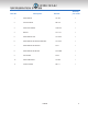
SIGN AND FRONT GRILL ASSEMBLY Sign Assembly Front Grill Assembly 16 RM-26
SIGN AND FRONT GRILL ASSEMBLY Sign Assembly Quantity Item No. Description Part No. per cooler 1 HEADER SIGN RIGHT PROFILE PL-634-GREY-8.875 1 2 HEADER SIGN LEFT PROFILE PL-634-GREY-8.
115V./60 Hz.
TROUBLESHOOTING Possible causes and solutions PROBLEM COMPRESSOR WILL NOT START POSSIBLE CAUSE SOLUTION NO VOLTAGE IN THE ELECTRICAL SOCKET USE A VOLTMETER TO CHECK THE VOLTAGE THE ELECTRICAL CONDUCTOR OR WIRES MAY BE CUT USE AN OHMMETER, TO CHECK FOR CONTINUITY DEFECTIVE ELECTRICAL COMPONENTS SUCH AS: THERMOSTAT, RELAY, THERMAL PROTECTOR, ETC.
PROBLEM POSSIBLE CAUSE SOLUTION THE TEMPERATURE IS NOT COLD ENOUGH THE REFRIGERATOR HAS BEEN PLACED AT AN INADEQUATE LOCATION THE UNIT MUST NOT BE NEAR STOVES, WALLS THAT ARE EXPOSED TO THE SUN, OR PLACES THAT LACK SUFFICIENT AIR FLOW THE REFRIGERATOR HAS BEEN USED IMPROPERLY THE SHELVES MUST NEVER BE COVERED WITH ANY TYPE OF PLASTIC OR OTHER MATERIAL THAT WILL BLOCK THE CIRCULATION OF COLD AIR WITHIN THE REFRIGERATOR THE REFRIGERATOR HAS BEEN OVERCHARGED WITH THE REFRIGERANT GAS CHE
PROBLEM EXTREME CONDENSATION INSIDE THE REFRIGERATOR POSSIBLE CAUSE THERMOSTAT’S AMBIENT SENSOR IS LOOSE OR INSTALLED IMPROPERLY THE OUTSIDE ENVIRONMENT’S RELATIVE HUMIDITY IS VERY HIGH (OVER 75%) THE REFRIGERATOR DOOR WON’T SHUT COMPLETELY NO ILLUMINATION SOLUTION CORRECTLY FASTEN THE THERMOSTAT’S AMBIENT SENSOR THIS TYPE OF OCCURRENCE IS CAUSED BY LOCAL CLIMATIC CONDITIONS AND NOT BY THE REFRIGERATED UNIT CHECK THE DOOR AND/OR THE MAGNETIC GASKET.
REFRIGERATION SYSTEM Component Description COMPRESSOR: The compressor is a factory sealed unit located underneath (outside) the cooling cabinet. This pump is activated by a motor which draws low pressure vapor (refrigerant) from the evaporator. It then compresses the gas and forces it into the condenser at a high pressure. STARTER RELAY: The starter relay is attached on one side of the compressor box. The compressor motor has two windings: one for starting and another for running.
REFRIGERATION SYSTEM Component Description EVAPORATOR: The evaporator is located inside the cooling cabinet. As the gas flows at a low pressure through the evaporator, it absorbs serpentine and removes the heat from inside the cabinet. EVAPORATOR FAN MOTOR: This device produces the required circulation of air through the cooling cabinet as well as over the surface of the evaporator’s serpentine thermal exchange area. This fan motor runs continuously.
THE REFRIGERATION CYCLE 1. As the temperature inside the cooling compartment increases, it is detected by the thermostats’ sensor. The thermostat then turns the compressor and the condenser motor on once the programmed temperature is reached. 2. The compressor recirculates the refrigerant throughout the system by drawing the refrigerant gas at a low vapor pressure from the evaporator. Then it compresses the refrigerant and forces it into the condenser. 3.
RM-26 25 1Axxxx-010