Hoshizaki Hoshizaki America, Inc. Self-Contained Cubelet Models C-101BAH C-101BAH-DS C-101BAH-AD C-101BAH-ADDS “A Superior Degree of Reliability” INSTRUCTION MANUAL www.hoshizaki.
WARNING Only qualified service technicians should install and service the appliance. To obtain the name and phone number of your local Hoshizaki Certified Service Representative, visit www.hoshizaki.com. No installation or service should be undertaken until the technician has thoroughly read this Instruction Manual. Likewise, the owner/manager should not proceed to operate the appliance until the installer has instructed them on its proper operation.
IMPORTANT This manual should be read carefully before the appliance is installed and operated. Read the warnings and guidelines contained in this manual carefully as they provide essential information for the continued safe use and maintenance of the appliance. Retain this manual for any further reference that may be necessary. CONTENTS Important Safety Information.................................................................................................. 4 I. Specifications..........................
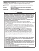
Important Safety Information Throughout this manual, notices appear to bring your attention to situations which could result in death, serious injury, damage to the appliance, or damage to property. WARNING Indicates a hazardous situation which could result in death or serious injury. NOTICE Indicates a situation which could result in damage to the appliance or property. IMPORTANT Indicates important information about the installation, use, and care of the appliance.
WARNING, continued • The appliance is not intended for use by persons (including children) with reduced physical, sensory, or mental capabilities, or lack of experience and knowledge, unless they have been given supervision or instruction concerning use of the appliance by a person responsible for their safety. • Young children should be properly supervised around the appliance. • Do not climb, stand, or hang on the appliance or appliance door or allow children or animals to do so.
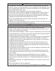
I. Specifications A. Construction Top Panel Ice Discharge Opening Bin Control Thermostat Bulb Scoop Holder Slope Magnet Catch Front Panel Control Switch Door Power Cord Louver B. Electrical and Refrigerant Data The nameplate provides electrical and refrigerant data. The nameplate is located inside the storage bin. For certification marks, see the nameplate. We reserve the right to make changes in specifications and design without prior notice.
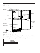
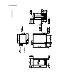
C. Dimensions/Connections Units: mm [in.] 1.
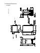
Units: mm [in.] 2.
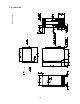
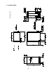
Units: mm [in.] 3.
Units: mm [in.] 4.
II. Installation Instructions WARNING • The appliance must be installed in accordance with applicable national, state, and local codes and regulations. • CHOKING HAZARD: Ensure all components, fasteners, and thumbscrews are securely in place after installation. Make sure that none have fallen into the storage bin. A. Checks Before Installation • Visually inspect the exterior of the shipping container and immediately report any damage to the carrier.
2. Built-In Installation Site NOTICE • Do not let the weight of the counter rest on the appliance. • Do not install the appliance in a corner where the door will interfere with other equipment or where the appliance cannot be pulled out for service. Installation Space Model Height C-101BAH C-101BAH-DS 34" (864 mm) minimum C-101BAH-AD C-101BAH-ADDS 32" (814 mm) minimum Width Depth 15" (381 mm) minimum 24" (610 mm) minimum Between Two Cabinets C-101BAH C-101BAH-DS Min.
C. Door 1. C-101BAH, C-101BAH-AD a) Door Reversal If you would like to reverse the door swing, follow the steps below. Otherwise, skip to section "II.D. Setup." 1) While maintaining a hold on the door, remove the hinge stop pin from hinge (B). Pull out the bottom of the door slightly and gently remove the door from hinge (A). See Fig. 1. Hinge (B) Hinge (A) Fig. 1 Hinge Stop Pin 2) Remove the 2 bolts securing the top panel, then lift it off. See Fig. 2. Top Panel Bolts Fig.
4) Remove hinge (B) from the right side of the appliance and the 2 filler screws from the left side. Attach the 2 filler screws to the right side and attach hinge (B) to the left side. See Fig. 4. 5) Rotate the top panel 180° from its previous position. This brings the notch that was previously in the right rear to the left front. See Fig. 5. Hook the rear part of the panel on the body, then secure the front with the 2 bolts removed in step 2. Top Panel Screws Notch Hinge (B) Filler Screws Fig. 4 Fig.
2. C-101BAH-DS, C-101BAH-ADDS a) Overlay Panel Fabrication and Attachment IMPORTANT The overlay panel must be crafted by a professional cabinet maker to ensure quality results. (1) Parts Ensure that all parts required for the overlay panel assembly are contained in the accessories bag. Overlay Panel Parts No. Description 1 Part Number Qty.
(2) Overlay Panel Specification Use the specification that applies to your appliance (C-101BAH-DS or C-101BAH-ADDS) and the directions that follow to prepare your overlay panel. ) ) ( ) ( ) ( ) ( ( ) ( ) ) ( ) ( ) ( ( (a) C-101BAH-DS C-101BAH-DS Overlay Panel Specification Overlay Panel Height 29 17/32" (750 mm) Overlay Panel Width 14 13/16" (376 mm) Overlay Panel Thickness 5/8" (16 mm) minimum; 3/4" (19 mm) maximum Overlay Panel and Door Weight (total) 20 lb.
) ) ( ) ( ) ( ) ( ( ) ( ) ) ( ) ( ) ( ( (b) C-101BAH-ADDS C-101BAH-ADDS Overlay Panel Specification Overlay Panel Height 27 9/16" (700 mm) Overlay Panel Width 14 13/16" (376 mm) Overlay Panel Thickness 5/8" (16 mm) minimum; 3/4" (19 mm) maximum Overlay Panel and Door Weight (total) 20 lb.
(3) Fabrication of Overlay Panel Fabricate the overlay panel as outlined in the specification on the previous page and the instructions below. 1) Rout a channel at the bottom of the overlay panel to the proper dimensions. See "(C) Routed Area" in the specification diagram and Fig. 8. 2) Drill six 1/4" diameter (hardwood may require slightly larger diameter) holes 3/8" (10 mm) deep in the locations designated. NOTICE! Use care when drilling holes for mounting hardware.
6) If you would like to reverse the door hinges, do the following: a) Contact your local distributor to purchase Hoshizaki Kit HS‑0229. The kit contains "hinge (A)-left." b) Remove the 2 bolts securing the top panel, then lift it off. See Fig. 11. c) Remove hinge (A)-right and the bracket from the right side of the appliance. Set aside hinge (A)‑right; it is not needed. Remove the top brace from the left side. Fasten hinge (A)-left and the bracket to the left side and the top brace to the right side.
7) Remove the bushings from hinge (C1) and hinge (C2) (the hinges attached to the door). See Fig. 16. 8) Remove the gasket from the door. See Fig. 17. Bushing Gasket Hinge Fig. 17 Fig. 16 9) Temporarily fasten the overlay panel to the door using 2 of the M4×25 pan head screws provided. NOTICE! Ensure that the back surface of overlay panel is flat before attaching. See Fig. 18. 10) Mark the centerpoint of the hinge (C1) and hinge (C2) holes that extend over the overlay panel. See Fig. 19.
(4) Attachment of Overlay Panel to Door 1) Fasten the sheet metal bracket to the overlay panel using the two M4×8 truss head screws provided. Snug the screws, but do not tighten. See Fig. 20. 2) Temporarily fasten the overlay panel to the door using 2 of the M4×25 pan head screws provided. See Fig. 21. Overlay Panel Screws Snug the screws, but do not tighten. Sheet Metal Bracket Fig. 20 Fig. 21 3) Adjust the sheet metal bracket so that it is flush with the bottom of the door. See Fig. 22.
7) Tighten the four M4×25 pan head screws installed in step 5. See Fig. 26. 8) Replace the door gasket in its proper orientation. Reinsert the bushings into hinge (C1) and hinge (C2) (the hinges attached to the door). See Fig. 27. Bushing Tighten the screws. Gasket Bushing Fig. 26 Fig. 27 9) Attach the door to hinge (A), then continue to maintain a hold on the door. Screw the hinge stop pin into hinge (B) until it is tight. See Fig. 28.
D. Setup 1) Position the appliance in the selected permanent location. 2) Level the appliance from side-to-side and front-to-rear by adjusting the feet. E. Electrical Connection WARNING • Electrical connection must meet national, state, and local electrical code requirements. Failure to meet these code requirements could result in death, electric shock, serious injury, fire, or damage. • The appliance requires an independent power supply of proper capacity. See the nameplate for electrical specifications.
F. Water Supply and Drain Connections WARNING Water supply and drain connections must be installed in accordance with applicable national, state, and local regulations. NOTICE • Normal operating water temperature must be within 45°F to 90°F (7°C to 32°C). Operation of the appliance, for extended periods, outside of this normal temperature range may affect appliance performance. • Water supply pressure must be a minimum of 7 PSIG and a maximum of 113 PSIG.
• For gravity drain installation, drain must have 1/4" fall per foot (2 cm per 1 m) on horizontal runs to get good flow. A vented tee connection is also required for proper flow. Extend the vent at least 12" (30 cm) above the drain outlet. • For optional drain pump installation, refer to the instructions included with the pump.
G. Final Checklist WARNING CHOKING HAZARD: Ensure all components, fasteners, and thumbscrews are securely in place after installation. Make sure that none have fallen into the storage bin.
III. Operating Instructions A. Important Notes About Usage WARNING • Only qualified service technicians should install and service the appliance. • Failure to install, operate, and maintain the equipment in accordance with this manual will adversely affect safety, performance, component life, and warranty coverage. • To reduce the risk of electric shock, do not touch the control switch or plug with damp hands.
NOTICE • Protect the floor when moving the appliance to prevent damage to the floor. • If using the optional drain pump (HS-5061), test its operation every time the appliance is cleaned and sanitized. See "IV.E. Optional Drain Pump HS-5061" for details. If the optional drain pump is not operating properly, water could back up and overflow, leading to costly water damage. • To help ensure the storage bin drain remains clear, follow the instructions in "IV.C.
B. Startup WARNING All parts are factory-adjusted. Improper adjustments may adversely affect safety, performance, component life, and warranty coverage. NOTICE • If the appliance is turned off, wait for at least 3 minutes before restarting the appliance to prevent damage to the compressor. • At startup, confirm that all internal and external connections are free of leaks. 1) Open the water supply line shut-off valve. 2) Make sure the control switch is in the "OFF" position.
IV. Maintenance The appliance must be maintained in accordance with the instruction manual and labels provided with the appliance. Consult with your local Hoshizaki Certified Service Representative about maintenance service. To obtain the name and phone number of your local Hoshizaki Certified Service Representative, visit www.hoshizaki.com. WARNING • Only qualified service technicians should service the appliance.
A. Maintenance Schedule The maintenance schedule below is a guideline. More frequent maintenance may be required depending on water quality, the appliance's environment, and local sanitation regulations. Maintenance Schedule Frequency Area Weekly Monthly Every 3 Months Every 6 Months Task Scoop Clean the scoop using a neutral cleaner. Rinse thoroughly after cleaning. Drain the Appliance Move the control switch to the "DRAIN" position. Allow the water system to drain for 1 minute.
B. Cleaning and Sanitizing Instructions The appliance must be cleaned and sanitized at least twice a year. More frequent cleaning and sanitizing may be required in some conditions. WARNING • To prevent injury to individuals and damage to the appliance, do not use ammonia type cleaners. • Carefully follow any instructions provided with the cleaning and sanitizing solutions.
7) Make sure at least 10 minutes have elapsed since you poured the cleaning solution over the extruding head, then move the control switch to the "ICE" position. 8) Allow the appliance to make ice for 20 minutes, then move the control switch to the "DRAIN" position. 9) Allow the water system to drain for 1 minute. 10) Move the control switch to the "ICE" position. 11) After the gear motor starts, move the control switch to the "DRAIN" position. 12) Allow the water system to drain for 1 minute.
5. Sanitizing Procedure - Final 1) Using a clean funnel and hose, pour 1 qt (1 l) of sanitizing solution over the extruding head. Allow the appliance to sit for 10 minutes before operation. 2) Move the control switch to the "ICE" position. 3) Allow the appliance to make ice for 20 minutes, then move the control switch to the "DRAIN" position. 4) Allow the water system to drain for 1 minute. 5) Move the control switch to the "ICE" position.
D. Condenser Check the condenser once a year, and clean if required by following the steps below. More frequent cleaning may be required depending on location. WARNING Condenser fins are sharp. Use care when cleaning. 1) Move the control switch to the "OFF" position, then unplug the appliance from the electrical outlet. WARNING! To reduce the risk of electric shock, do not touch the control switch or plug with damp hands. 2) Remove the screws securing the front panel, then remove it. See Fig. 32.
E. Optional Drain Pump HS-5061 If the optional drain pump (HS-5061) is installed, test its operation at least twice a year as outlined below. Note that the pump has power even when the control switch is in the "OFF" position. NOTICE If the optional drain pump is not operating properly, it will adversely affect performance, component life, and warranty coverage and may result in costly water damage. 1) Move the control switch to the "OFF" position, then unplug the appliance from the electrical outlet.
V. Preparing the Appliance for Periods of Non-Use During extended periods of non-use, extended absences, or in sub-freezing temperatures, follow the instructions below. When the appliance is not used for two or three days under normal conditions, it is sufficient to move the control switch to the "OFF" position. WARNING Only qualified service technicians should service the appliance.
14) Plug the appliance back in, then move the control switch to the "DRAIN" position. 15) Blow out the reservoir outlet hose using the compressed air or carbon dioxide supply. 16) Move the control switch to the "OFF" position, then unplug the appliance from the electrical outlet. 17) Reconnect the reservoir outlet hose to the reservoir, then secure with the clamp. Make sure all hoses are connected and secure. 18) Replace the rear panel in its correct position.
VI. Disposal The appliance contains refrigerant and must be disposed of in accordance with applicable national, state, and local codes and regulations. Refrigerant must be recovered by properly certified service personnel.
HOSHIZAKI AMERICA, INC. 618 Hwy. 74 S., Peachtree City, GA 30269 USA TEL (770) 487-2331 FAX (770) 487-3360 www.hoshizaki.