Instruction Manual Refrigerated Kitchen Equipment Models Undercounter Worktop Prep Table hoshizakiamerica.
WARNING Only qualified service technicians should install and service the appliance. To obtain the name and phone number of your local Hoshizaki Certified Service Representative, visit www.hoshizaki.com. No installation or service should be undertaken until the technician has thoroughly read this Instruction Manual. Likewise, the owner/manager should not proceed to operate the appliance until the installer has instructed them on its proper operation.
IMPORTANT This manual should be read carefully before the appliance is installed and operated. Read the warnings and guidelines contained in this manual carefully as they provide essential information for the continued safe use and maintenance of the appliance. Retain this manual for any further reference that may be necessary. CONTENTS Important Safety Information.................................................................................................. 4 I. Installation Instructions...............
Important Safety Information Throughout this manual, notices appear to bring your attention to situations which could result in death, serious injury, damage to the appliance, or damage to property. DANGER WARNING NOTICE IMPORTANT Indicates a hazardous situation that, if not avoided, will result in death or serious injury. Indicates a hazardous situation that, if not avoided, could result in death or serious injury.
WARNING The appliance should be destined only to the use for which it has been expressly conceived. Any other use should be considered improper and therefore dangerous. The manufacturer cannot be held responsible for injury or damage resulting from improper, incorrect, and unreasonable use. Failure to install, operate, and maintain the appliance in accordance with this manual will adversely affect safety, performance, component life, and warranty coverage.
• Do not block air inlets or outlets, otherwise cooling performance may be reduced. • Do not tightly pack the cabinet. Allow some space between items to ensure good air flow. Also allow space between items and interior surfaces. • Do not put warm or hot foods in the cabinet. Let them cool first, or they will raise the cabinet temperature and could deteriorate other foods in the cabinet or overload the appliance. • Food storage and handling must comply with applicable codes and regulations.
NOTICE WARNING, continued Additional Warnings for Prep Table Models • The entire rail must always be covered by rail dividers and pans (1/6 size, up to 6" (15 cm) deep). Otherwise, the appliance will not cool properly. • Use only 1/6 size pans up to 6" (15 cm) deep. Do not use damaged pans. • Ingredients must be pre-chilled to 37°F (3°C) or less before placing in rail. • Keep the rail cover closed when not actively preparing food. • The rail is for keeping ingredients cool while preparing food.
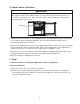
I. Installation Instructions WARNING • The appliance must be installed in accordance with applicable national, state, and local regulations. • Appliance is heavy. Use care when lifting or positioning. Work in pairs when needed to prevent injury or damage. Do not lift using the top section or the doors/drawers. • Do not tilt the appliance more than 45°. A. Location WARNING • The appliance is not intended for outdoor use. • Undercounter and Worktop: Certified to maintain NSF temperatures up to 100°F (38°C).
B. Checks Before Installation WARNING Refer to the nameplate for electrical specifications. The nameplate is located on the right side wall of the cabinet interior. For more electrical connection details, see "I.E. Electrical Connection." We reserve the right to make specification and design changes without prior notice. Nameplate • Visually inspect the exterior of the shipping package and immediately report any damage to the carrier.
3) Attach the casters to the bottom of the appliance. Locking casters should be attached to the front of the appliance. See Fig. 1. Note: For UR_WR_SR48A(-xx), rear caster brackets must be installed with the rear casters as illustrated. See Fig. 2. NOTICE! Ensure casters are completely threaded into appliance and tight. Door Locking Casters in Front Rear Caster Bracket Rear Caster Bracket Casters UR_WR_SR48A(-xx) Fig. 1 Fig.
4) Tighten the caster. See Fig. 5. NOTICE! Make sure the caster is tight and no slack is left between the caster, shim plates, and appliance. 5) Repeat the procedure for other casters as needed. 6) Lower the appliance to the floor. Shim Plates Caster Tight Against Shim Plates and Unit Fig. 5 Caster 2. Check the Refrigeration Circuit • Visually check that the refrigerant lines do not rub or touch other lines or surfaces and that the condenser fan blade turns freely.
5. Install the Rail Dividers and Pans (Prep Table Models) Install the rail dividers and 1/6 size pans included with the appliance. See Fig. 7 and the table below. The entire rail must always be covered by rail dividers and pans. Otherwise, the appliance will not cool properly. Use pans with a depth of up to 6" (15 cm). Do not use damaged rail dividers or pans. Pans Fig.
Rail Divider Layout, continued -16 Models SR60A-16, SR72A-16 Front-to-Back: HS-5188 (12-5/8"; 322 mm) Qty 3 Side-to-Side (Outer): HS-5189 (13-5/8"; 346 mm) Qty 2 Side-to-Side (Center): HS-5190 (13-1/2"; 344 mm) Qty 2 -18, -18M Models SR48A-18M, SR60A-18M, SR72A-18M SR72A-18 Front-to-Back: HS-5188 (12-5/8"; 322 mm) Qty 2 Side-to-Side (Outer): HS-5191 (20-5/8"; 523 mm) Qty 2 Side-to-Side (Center): HS-5192 (20-1/2"; 520 mm) Qty 1 Front-to-Back: HS-5184 (20-3/4"; 526 mm) Qty 2 Side-to-Side: HS-5185 (Outer)
6. Install the Rail Cover (Prep Table Models) 1) Install and tighten the pivot pins, washers, and pivot screws on the rail hood with the pivot pin shafts facing inward towards the open rail area. See Fig. 8. 2) Models with Two Rail Covers: Install and tighten the pivot pins, washers, and pivot screws to the center hinge brackets, then secure the center hinge brackets using the 4×8 screws provided. See Fig. 9.
7. Attach the Cutting Board Brackets and Cutting Board (Prep Table Models) 1) Remove the screws from the cutting board bracket mounting locations on the appliance. See Fig. 11a for Sandwich Top models and Fig. 11b for Mega Top models. 2) Use the screws removed in step 1 to attach the cutting board brackets. 3) Slide the cutting board into the cutting board brackets. WARNING! Make sure the cutting board brackets and cutting board are secure. Otherwise, the cutting board could come off and cause injury. Fig.
D. Solid Door Reversal The appliance is provided with a cabinet design which, after being delivered to the installation location, permits changing of the door swing from left to right or right to left. To change the door swing, follow the steps below. Example shows change from right hinged to left hinged. WARNING • Wear proper PPE (personal protection equipment) when executing these procedures (safety glasses and gloves). • Keep fingers away from edge of upper hinge bracket.
Upper Hinge Bracket Removal and Spring Cartridge Relocation 7) While preventing the upper hinge bracket from rotating, remove the upper hinge bracket from the spring cartridge. See Fig. 15. Note which side of the upper hinge bracket is facing up. 8) Remove the filler cap, filler screws, and spring cartridge. See Fig. 16. Leave the thrust washers in place on the spring cartridge. NOTICE! Spring cartridge may be difficult to remove. Be careful not to damage the finish.
Door Installation 12) Remove the black plastic filler cap located from the hole above where the spring cartridge screw will line up. Note: The black plastic filler cap is not reusable. 13) Remove the upper hinge bracket screws from the new location and apply Loctite Threadlocker Blue 242 or 243 to the threads. Next, start the upper hinge bracket outer screw into the appliance. Rotate a few threads into the appliance; do not tighten the screw. See Fig. 20.
16) Close the door and tighten the upper hinge bracket outer screw. See Fig. 22. Door Fully Closed Upper Hinge Bracket Outer Screw Upper Hinge Bracket Fig. 22 17) Check the door operation to assure it opens and closes properly. Note: Hold door at 45° angle from closed position and release. Door should close on its own. If not, adjust hinge bracket. 18) Unlock the casters and move the appliance back into its original position.
2) Remove the drawers. Pull the drawer out to its fully extended position. Open the safety clips (one on each side) by sliding them forward, then rotating them up. See Fig. 24. Lift up on the handle slightly, then pull to disengage the drawer. Be sure to support the rear and front of the drawer while removing it. WARNING! Be sure to close the safety clips when reinstalling the drawer. Safety Clip Closed Safety Clip Open Safety Clips Drawer Slides Upper Drawer Lower Drawer Fig.
4) Remove the hex-bolts from the 2 right (front and rear) and 2 left (front and rear) brackets (2 hex-bolts per bracket), then remove the right and left drawer frames. See Fig. 26.
Pilaster and Inner Brackets Relocation 5) Remove the shelf from the door section, then remove the pilasters. See Fig. 27. Right Side Pilasters Vertical Mullion Shelf Center Rear Drawer Frame Bracket Center Rear Pilaster Vertical Mullion Pilaster Fig. 27 6) Remove the center rear drawer frame bracket and the filler screw. See Fig. 28. Slide the center rear drawer frame bracket over to the new location and secure it. Place the filler screw in the former center rear drawer frame bracket hole.
8) Place and secure the pilasters and shelf support clips in their new location. See Fig. 30. Replace the shelf. Center Rear Pilaster Left Side Pilasters Center Rear Drawer Frame Bracket Vertical Mullion Bracket Vertical Mullion Pilaster Vertical Mullion Fig. 30 Door Relocation 9) With the door closed, loosen, but do not remove, the upper hinge bracket outer screw. See Fig. 31. Next, open the door to the fully open position and remove the upper hinge bracket inner screw. See Fig. 32.
12) Remove the lower hinge bracket. See Fig. 33. Be sure to leave the thrust washer in place. 13) Install the lower hinge bracket in its new location. Be sure the lower hinge bracket is pushed all the way in and the thrust washer is in its original position. Lower Hinge Bracket Mounting Holes Thrust Washer Thrust Washer Lower Hinge Bracket Lower Hinge Bracket Bolts Fig. 33 Bolts 14) Remove the black plastic filler cap located from the hole above where the spring cartridge screw will line up.
18) Close the door and tighten the upper hinge bracket outer screw. See Fig. 36. Upper Hinge Bracket Door Fully Closed Upper Hinge Bracket Outer Screw Fig. 36 19) Check the door operation to assure it opens and closes properly. Note: Hold door at 45° angle from closed position and release. Door should close on its own. If not, adjust hinge bracket.
Drawer Relocation Left Drawer Frame Relocation 20) Place the left rear bracket in place on the center rear drawer frame bracket with hex‑bolts removed in step 4. Leave loose, do not tighten at this time. See Fig. 36. 21) Place the left front bracket in place on the vertical mullion bracket with the hex-bolts removed in step 4. See Fig. 37. Leave loose, do not tighten at this time.
Right Drawer Frame Relocation 23) Place the right rear bracket in place on the right side panel with the hex-bolts removed in step 4. Leave loose, do not tighten at this time. See Fig. 39. 24) Place the right front bracket in place on the right side panel with the hex-bolts removed in step 4. Leave loose, do not tighten at this time. See Fig. 39. Hex-Bolts Right Rear Bracket Right Rear Bracket Right Front Bracket Right Front Bracket Vertical Mullion Fig.
Horizontal Mullion Replacement 26) Place the horizontal mullion in its correct position and secure with screws removed in step 3. 27) Place a bead of food grade silicone down the 2 outside vertical gaps between the mullion and appliance. See Fig. 41. Horizontal Mullion Silicone Location for Horizontal Mullion Silicone Location for Horizontal Mullion Model Shown: UR48A-D2 Fig.
28) Place the lower drawer in the lower drawer slides and the upper drawer in the upper drawer slides. See Fig. 42. WARNING! Be sure to close the safety clips when reinstalling the drawer. 29) Make sure all gaskets are making good contact. Using a flashlight, check that there are no openings around all gaskets. 30) Unlock the casters and move the appliance back into its original position. Lock the casters once in position, then plug the appliance back into the electrical outlet.
G. Electrical Connection WARNING • Electrical connection must meet national, state, and local electrical code requirements. Failure to meet these code requirements could result in death, electric shock, serious injury, fire, or severe damage to equipment. • The appliance requires an independent power supply of proper capacity. See the nameplate for electrical specifications.
H.
II. Operating Instructions A. Important Notes About Usage DANGER Risk of Fire or Explosion Flammable Refrigerant Used • Do not use mechanical devices to defrost. • Do not puncture refrigerant tubing. Risk of fire or explosion due to puncture of refrigerant tubing; follow handling instructions carefully. • Do not place any potential ignition sources in or near the appliance. Risque De Feu Ou D'Explosion Le Frigorigène Est Inflammable • Ne pas utiliser d'appareils mécaniques pour dégivrer le réfrigérateur.
WARNING, continued • The appliance is designed only for temporary storage of food. Employ sanitary methods. Use for any other purposes (for example, storage of chemicals or medical supplies such as vaccine and serum) could cause deterioration of stored items. • Do not block air inlets or outlets, otherwise cooling performance may be reduced. • Do not tightly pack the cabinet. Allow some space between items to ensure good air flow. Also allow space between items and interior surfaces.
NOTICE • Protect the floor when moving the appliance to prevent damage to the floor. • Keep ventilation openings, in the appliance enclosure or in the built-in structure, clear of obstruction. Do not place anything on top of the appliance in an undercounter installation. There must be at least 1.5" (4 cm) overhead clearance for proper ventilation. The factory-installed rear bumpers must be in place to ensure proper rear clearance.
B. Startup WARNING All parts are factory-adjusted. Improper adjustments may adversely affect safety, performance, component life, and warranty coverage. 1) Plug the appliance into the electrical outlet. WARNING! To reduce the risk of electric shock, do not touch the plug with damp hands. At startup, there is a slight delay before the compressor starts. 2) Allow the appliance to cool down prior to loading it with food products.
D. Defrost DANGER Risk of Fire or Explosion Flammable Refrigerant Used • Do not use mechanical devices to defrost. • Do not puncture refrigerant tubing. Risk of fire or explosion due to puncture of refrigerant tubing; follow handling instructions carefully. Risque De Feu Ou D'Explosion Le Frigorigène Est Inflammable • Ne pas utiliser d'appareils mécaniques pour dégivrer le réfrigérateur. • Ne pas perforer la tubulure contenant le frigorigène.
E. Food Storage WARNING • Storage of foods should follow all local codes and regulations. • The appliance is designed only for temporary storage of food. Employ sanitary methods. Use for any other purposes (for example, storage of chemicals or medical supplies such as vaccine and serum) could cause deterioration of stored items. • Do not block air inlets or outlets, otherwise cooling performance may be reduced. • Do not tightly pack the cabinet. Allow some space between items to ensure good air flow.
F. Safety Devices 1. Compressor External or Internal Protector If combined temperature/amperage value is above the limit specified by the compressor manufacturer, the compressor protector operates independently to turn off the compressor. The compressor protector de-energizes the compressor until the temperature/amperage value returns to an acceptable level. 2. Short-Cycle Protection There is a 2-minute minimum off-time and on-time for the compressor.
III. Cleaning and Maintenance Instructions A. Cleaning WARNING • Unplug the appliance before cleaning to prevent electric shock by unexpected entrance of water into the appliance or injury by moving parts. To reduce the risk of electric shock, do not touch the plug with damp hands. • Before cleaning the appliance, move all foods into another clean refrigerator or freezer. • Do not splash, pour, or spray water directly onto or into the appliance.
6. Drawers Drawers and drawer slides are removable. • To remove a drawer: Remove all items from the drawer. Pull the drawer out to its fully extended position. Open the safety clips (one on each side) by sliding them forward, then rotating them up. See Fig. 44. Lift up on the handle slightly, then pull to disengage the drawer. Be sure to support the rear and front of the drawer while removing it. WARNING! Be sure to close the safety clips when reinstalling the drawer.
9. Rail, Rail Hood, and Rail Cover (Prep Table Models) Spills and splashes should be wiped up promptly to avoid unpleasant odors. Wipe the rail area, the rail hood, and the rail cover occasionally with a clean, damp sponge or cloth containing a neutral cleaner. Clean any rust colored spots using a non‑abrasive cleanser. Do not pour or spray water into the rail area. WARNING! • Support the rail cover when cleaning. Otherwise, the rail cover could close suddenly and cause injury. • Metal edges can cause cuts.
IV. Preparing the Appliance for Periods of Non-Use When shutting down the appliance for more than one week, follow the instructions below. WARNING When preparing the appliance for long storage, prevent the doors/drawers from closing to reduce the risk of children getting trapped. NOTICE When preparing the appliance for long storage, clean the appliance. See "III.A. Cleaning" for details. 1) Before shutting down the appliance, move all foods into another clean refrigerator or freezer.
V. Disposal DANGER Risk of Fire or Explosion Flammable Refrigerant Used • Follow handling instructions carefully in compliance with U.S. government regulations. • Do not puncture refrigerant tubing. Risk of fire or explosion due to puncture of refrigerant tubing; follow handling instructions carefully. • Dispose of properly in accordance with federal or local regulations.
618 Hwy. 74 South, Peachtree City, GA 30269 USA (P) 770.487.2331 (F) 770.487.3360 hoshizakiamerica.