Service Manual Refrigerated Kitchen Equipment Steelheart B Series Models Undercounter Worktop Prep Table hoshizakiamerica.
WARNING Only qualified service technicians should install and service the appliance. To obtain the name and phone number of your local Hoshizaki Certified Service Representative, visit www.hoshizaki.com. No service should be undertaken until the technician has thoroughly read this Service Manual. Failure to service and maintain the appliance in accordance with this manual will adversely affect safety, performance, component life, and warranty coverage.
IMPORTANT This manual should be read carefully before the appliance is serviced. Read the warnings and guidelines contained in this booklet carefully as they provide essential information for the continued safe use, service, and maintenance of the appliance. Retain this booklet for any further reference that may be necessary. CONTENTS Important Safety Information.................................................................................................. 4 I.
Important Safety Information Throughout this manual, notices appear to bring your attention to situations which could result in death, serious injury, damage to the appliance, or damage to property. DANGER WARNING NOTICE IMPORTANT Indicates a hazardous situation that, if not avoided, will result in death or serious injury. Indicates a hazardous situation that, if not avoided, could result in death or serious injury.
WARNING The appliance should be destined only to the use for which it has been expressly conceived. Any other use should be considered improper and therefore dangerous. The manufacturer cannot be held responsible for injury or damage resulting from improper, incorrect, and unreasonable use. Failure to install, operate, and maintain the appliance in accordance with this manual will adversely affect safety, performance, component life, and warranty coverage.
WARNING, continued • Children should be properly supervised around the appliance. • Do not climb, stand, or hang on the appliance or doors/drawers or allow children or animals to do so. Do not climb into the appliance or allow children or animals to do so. Death or serious injury could occur or the appliance could be damaged. • Be careful not to pinch fingers when opening and closing the doors/drawers or rail cover (SR models) or when handling food pans.
NOTICE WARNING, continued • Protect the floor when moving the appliance to prevent damage to the floor. • Keep ventilation openings, in the appliance enclosure or in the built-in structure, clear of obstruction. Do not place anything on top of the appliance in an undercounter installation. There must be at least 1.5" (4 cm) overhead clearance for proper ventilation. The factory-installed rear bumpers must be in place to ensure proper rear clearance.
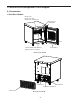
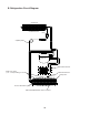
I. Construction and Refrigeration Circuit Diagram A. Construction 1.
2.
B.
Comp energized ConFM energized EvapFM energized 5-hr. DT starts Green LED on Red and Yellow LEDs off Evap. temp. at or below -4°F (-20°C) * or 5-hr DT terminates * 5-min. min. DT starts * 55-min. max. DT starts Comp de-energized ConFM de-energized EvapFM energized * * 5-min. minimum and 55-min. maximum DT starts DTh in control Evap. Temp. achieves 45°F (7.2°C) or 55-min. DT terminates, Defrost Terminated 1-hr. DLT starts 5-hr. DT starts Comp energized ConFM energized EvapFM energized a) 2-min.
Power on Yellow LED On (10-sec. Delay) Comp energized ConFM energized EvapFM energized 5-hr. DT starts Legend: Comp-compressor ConFM-condenser fan motor CTh-cabinet thermistor DH-defrost heater DT-defrost timer DTh-defrost thermistor EvapFM-evaporator fan motor CTh cools to setpoint EvapFM energized Comp de-energized ConFM de-energized CTh in control Defrost Termination: 46°F (7.7°C) achieved or 45 min. backup defrost timer terminated. Defrost: Time achieved. 5-hr. DT terminates 5-hr.
Comp energized ConFM energized EvapFM energized MH energized PH energized 5-hr. DT starts Power on Yellow LED On (10-sec. Delay) CTh in control * * 3-min. DOT terminates or Evap Temp. Achieves 10°F (-12°C) (FDD) 1-hr. DLT starts 5-hr. DT starts EvapFM energized 3-min DOT Terminates Defrost Termination: 55°F (°12.7C) achieved or 1 hr. backup defrost timer terminated. Evap. Temp. achieves 55°F (12.7°C) or 1-hr. DT terminates DH de-energized 3-min.
B. Service Diagnosis Risque De Feu Ou D'Explosion DANGER Risk of Fire or Explosion Flammable Refrigerant Used • Follow handling instructions carefully in compliance with U.S. government regulations. • Do not use mechanical devices to defrost. • Do not puncture refrigerant tubing. Risk of fire or explosion due to puncture of refrigerant tubing; follow handling instructions carefully. • Component parts shall be replaced with like components.
1. Diagnostic Procedures The diagnostic procedure is a sequence check that allows you to diagnose the electrical system and components. Before proceeding, check for correct installation and proper voltage per nameplate. See the table for default cabinet temperature control dial settings.
1) Unplug the appliance from the electrical outlet. 2) Remove the CM mounting bracket and place the CM in a place where the LEDs are visible. 3) Plug the appliance back into the electrical outlet. If appliance was in defrost when power supply was disconnected, defrost is terminated and normal cooling cycle begins. 4) Startup/Cool Down– All 3 LEDs flash on then off, then a solid yellow LED turns on for 10 sec., yellow LED turns off and solid green LED turns on (normal cooling cycle).
5) Cool Down Achieved–CTh reaches setpoint temperature. All Models: Comp and ConFM de-energize. UR/WR and UF/WF: EvapFM de‑energize. SR: EvapFM continues. Diagnosis: If temperature setpoint achieved and Comp, ConFM, and EvapFM does not de-energize (except SR), check CTh continuity. See "II.D. Thermistor Check." If CTh is defective, replace. If CTh is good and either the Comp, ConFM, or EvapFM continue, replace CM.
2a) Manually-Terminated: Set the CTCD to the off position, then back to original setting or unplugging and plugging back in to the electrical outlet. Defrost terminated. 2b) Temperature or Time Terminated: (1) UR/WR: 45°F (7.2°C) achieved or 55-min. backup DT terminates. If CTh calling for cooling, Comp and ConFM energize. EvapFM continues. (2) SR: 46°F (7.7°C) achieved or 45-min. backup DT terminates. DH de‑energizes. Comp, ConFM, and EvapFM energize. (3) UF/WF: 55°F (12.7°C) achieved or 1-hr.
(3) EvapFM Diagnosis UR/WR: EvapFM continues. If not, check for 115VAC at CM AUX 1 black-smooth (BK-SM) wire to a neutral white (W). If 115VAC is not present, replace CM. SR and UF/WF: Confirm EvapFM de-energizes. If not, check for 115VAC at CM AUX 1 black-smooth (BK-SM) to a neutral white (W). If 115VAC is present, confirm Comp and ConFM de-energized. Next, check DTh continuity. See "II.D. Thermistor Check." Replace as needed. If DTh confirmed, replace CM.
C. Control Module Check 1. Control Module Before replacing a CM that does not show a visible defect and that you suspect is bad, conduct the following check procedure. This procedure will help you verify your diagnosis. Always choose a neutral white (W) wire to establish a good power supply and neutral connection to CM. Check that 115VAC is present between CM Live In black (BK) wire and CM Neutral white (W) wire. Confirm defrost and cabinet thermistors are connected.
1a. Control Module LED Operation: The control module has 3 LEDs that illuminate based on the status of the thermistors. Red (R), Yellow (Y), and Green (G). a) Warm Cabinet Thermistor - Power on: All 3 LEDs turn on for 2 sec. then turn off. Next, yellow (Y) LED turns on for 10 sec. b) Warm Cabinet Thermistor - Compressor energizes: Yellow (Y) LED turns off, green (G) LED turns on (normal cooling cycle). c) Cool Cabinet Thermistor - Cabinet temperature achieved.
3. Defrost initiation 5) Manual Defrost Check: Unplug the appliance from the electrical outlet, then move the CTCD to the off position. Plug appliance back into the electrical outlet. The CM green, yellow, and red LED turn on. Rotate the CTCD clockwise to position 4 (green and red LED turn off, yellow LED remains on), move Counter-clockwise to position 2 (yellow LED turns off and red LED turns on), move back clockwise to position 8 (red LED remains on and green LED turns on). Defrost initiates.
D. Thermistor Check The cabinet thermistor works in conjunction with cabinet temperature control dial (CTCD) to control cabinet temperature. The defrost thermistor is used for defrost initiation and termination on all models and evaporator fan motor restart on UF/WF. • UR/WR: Defrost termination is 45°F (7.2°C). • SR: Defrost termination is 46°F (7.7°C). • UF/WF: Defrost initiation is below -31°F (-35°C). Defrost termination is 55°F (12.7°C). • UR/WR: Evaporator fan motor is energized during defrost.
E. Diagnostic Table Before consulting the diagnostic tables, check the following: • Check the cabinet temperature control dial setting. See the table for default cabinet temperature control dial settings.
1. Appliance Not Cooling Appliance Not Cooling - Possible Cause 1. Power Supply a) Unplugged, blown fuse, or tripped or defective circuit breaker. 2. Power Supply Cord and Plug 3. Wiring 4. Cabinet Thermistor 5. Control Module b) c) a) b) a) b) a) a) Loose connection. a) b) a) b) a) b) c) d) e) f) a) a) a) a) b) Fan blade binding. Not within specifications. Loose connection. Defective. Loose connection or disconnected. Defective. Loose, disconnected, or defective.
3. Defrost UR/WR Defrost - Possible Cause 1. Control Module (fails to initiate) See "II.C. Control Module Check" a) Defective-Cumulative 5-hr. defrost timer fails. 2. Control Module (fails to terminate) See "II.C. Control Module Check" a) Defrost thermistor connection loose. 3. Defrost Thermistor (Confirm DTh status. See "II.D. Thermistor Check") a) Defective. b) Defective-1-hr. defrost lock-out timer fails. b) Defective. SR and UF/WF Defrost - Possible Cause 1.
III. Controls and Adjustments A. Temperature Settings 1. Temperature Reading A thermometer with both °F and °C scales is mounted in the cabinet. See Fig. 1. 2. Cabinet Temperature The appliance features a cabinet temperature control dial (CTCD). The warmest setting is 1 and the coldest setting is 9. See the table for default cabinet temperature control dial settings.
B. Defrost There are 2 types of defrost: Off Cycle Defrost (with evaporator fan motor) and Heated Defrost (without evaporator fan motor). Manual Initiation (All Models): Unplug the appliance from the electrical outlet,then move the cabinet temperature control dial to the off position. Plug the appliance back into the electrical outlet. The Green, Yellow, and Red LED turn on briefly.
C. Safety Devices 1. Compressor External Protector (All Models) If combined temperature/amperage value is above the limit specified by the compressor manufacturer, the compressor external protector operates independently to turn off the compressor. The compressor external protector de-energizes the compressor until the temperature/amperage value returns to an acceptable level. D. Perimeter and Mullion Heaters (UF/WF only) UF/WF are equipped with perimeter and mullion heaters.
IV. Refrigeration Circuit and Component Service Information DANGER Risk of Fire or Explosion Flammable Refrigerant Used • Follow handling instructions carefully in compliance with U.S. government regulations. • Do not use mechanical devices to defrost. • Do not puncture refrigerant tubing. Risk of fire or explosion due to puncture of refrigerant tubing; follow handling instructions carefully. • Component parts shall be replaced with like components.
WARNING • Wear appropriate personal protective equipment (PPE) when servicing the appliance. • Technician must utilize a combustible gas leak detector at all times. • Notify everyone in the immediate area that you are working with flammable refrigerant. • Do not work on appliance in a confined space. Confirm area is well ventilated. • Identify and eliminate all possible ignition points in a 10 ft. (3 m) area around service area. • Do not use mechanical devices to defrost. • Use non-sparking tools.
A. Refrigeration Circuit Service Information WARNING • Repairs requiring the refrigeration circuit to be opened must be performed by properly trained and EPA-certified service personnel. • Use an electronic leak detector or soap bubbles to check for leaks. Add a trace of refrigerant to the system (if using an electronic leak detector), and then raise the pressure using nitrogen gas (140 PSIG). Do not use R‑290 as a mixture with pressurized air for leak testing.
2. Brazing DANGER Risk of Fire or Explosion Flammable Refrigerant Used • Servicing shall be done by factory authorized service personnel to minimize the risk of possible ignition due to incorrect parts or improper service. Risque De Feu Ou D'Explosion Le Frigorigène Est Inflammable • L’entretien doit être effectué par le personnel de service autorisé par le fabricant afin de minimiser les risques d’inflammation attribuables à l’installation d’une pièce inadéquate ou à la mauvaise exécution du service.
3. Evacuation 1) Attach a vacuum pump to the system. Be sure to connect the charging hoses to both high and low-side refrigerant piercing valves. IMPORTANT The vacuum level and vacuum pump may be the same as those for current refrigerants. However, the rubber hose and gauge manifold to be used for evacuation and refrigerant charge should be exclusively for POE oils. 2) Turn on the vacuum pump, then open the gauge manifold valves. Never allow the oil in the vacuum pump to flow backwards.
B. Component Service Information NOTICE When replacing a component listed below, see the notes to help ensure proper operation. Component Notes Compressor Install a new start relay and compressor external protector. WARNING! To reduce the risk of electric shock, be sure to reconnect the compressor's ground wire. After working with or around the cabinet thermistor, make sure the cabinet thermistor is in its correct position and secure.
V. Preparing the Appliance for Periods of Non-Use When shutting down the appliance for periods of non-use, follow the instructions below. WARNING Prevent the doors from closing to reduce the risk of children getting trapped. NOTICE Clean the cabinet interior, door gaskets, and shelves. 1) Before shutting down the appliance, move the stored food into another refrigerator or freezer. 2) Unplug the appliance from the electrical outlet.
VI. Disposal DANGER Risk of Fire or Explosion Flammable Refrigerant Used • Follow handling instructions carefully in compliance with U.S. government regulations. • Do not puncture refrigerant tubing. Risk of fire or explosion due to puncture of refrigerant tubing; follow handling instructions carefully. • Dispose of properly in accordance with federal or local regulations.
VII. Technical Information A. Electrical and Refrigerant Data Design Pressure (PSIG) Refrigerant (oz.) AC Supply Model (includes drawer models) Voltage Amperes HIGH LOW R290 UR/WR27B(-xxx), UR27B-GLP01, SR27B-(xxxxx) 2.3 115/60/1 3.0 360 190 UF/WF27B(-xx), UF27B-GLP01 1.9 UR/WR36B(-xx) and SR36B(-xxx) 115/60/1 3.0 360 190 2.
B. Wiring Diagrams 1.
2.
3.
4.