
Service Manual

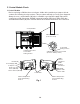
Table Of Contents
16
1) Unplug the appliance from the electrical outlet.
2) Remove the CM mounting bracket and place the CM in a place where the LEDs are
visible.
3) Plug the appliance back into the electrical outlet. If appliance was in defrost when power
supply was disconnected, defrost is terminated and normal cooling cycle begins.
4) Startup/Cool Down– All 3 LEDs ash on then off, then a solid yellow LED turns on for
10 sec., yellow LED turns off and solid green LED turns on (normal cooling cycle).
CTh Temperature above setpoint, Comp, ConFM, EvapFM, PH (UF/WF only), and
MH (UF/WF only) energize. 2-min. Comp on timer and 5-hr. DT starts.
a) CTh Diagnosis: If CTh fails, green and yellow LEDs ash on the CM. Conrm CTh is
properly connected to CM. Check Ohm reading of CTh. See "II.D. Thermistor Check."
Replace as needed.
b) CM Diagnosis: Conrm green LED is solid. If not, conrm CTh is above setpoint.
Next, check for 115VAC between CM Live In black (BK) wire and a neutral white
(W) wire. If 115VAC is not present, check power cord connections and breaker/fuse.
Conrm wiring connections are secure for both CM Live In black (BK) and a neutral
white (W) wire. If 115VAC is present, CTh is above setpoint, and CM green LED is
not on, replace CM.
c) Comp/ConFM Diagnosis: Check that Comp and ConFM energize. Next, check
for 115VAC at CM Comp violet(V) wire to a neutral white (W) wire. If 115VAC is not
present at CM Comp violet (V) to a neutral white (W) wire, check CTh status.
See "II.D. Thermistor Check." If CTh ohm reading is in proper range, replace CM.
Comp: If 115VAC is present, check Comp external overload, start or run cap
(ifapplicable), PTC relay or start relay, and Comp motor windings. Replace as
needed. ConFM: If 115VAC is present, check fan blade for binding, then check
ConFM motor windings. If Comp, ConFM, and EvapFM are energized and the
cabinet does not cool down, check for a restriction in the refrigeration circuit, low
refrigerant charge, or inefficient Comp.
d) EvapFM Diagnosis: Check that EvapFM(s) energize. If not, check for 115VAC at CM
Aux 1 black-smooth (BK-SM) wire to neutral white (W) wire. If 115VAC is not present,
replace CM. If 115VAC is present, check fan blades for binding, then check EvapFM
motor windings.
e) PH and MH Diagnosis (UF/WF only): PH and MH follow Comp operation. When
Comp is energized, PH and MH are energized. If 115VAC is present, check amp draw
of PH and MH. If an amp reading is not present, check the continuity of PH
and MH. If defective, replace PH or MH.
f) Glass Door Cabinet LEDs Diagnosis: LED(s) are activated by CLS. If CLS is
engaged and LED(s) fail to turn on, check for 115VAC at both CLS (Y) wires to a
neutral white (W) wire. If 115VAC is present on one end and not the other, check CLS
continuity. If open replace CLS. If CLS is closed and 115VAC is present on both CLS
(Y) wires to a neutral (W), check for 24VDC at DCD black (BK) wire to DCD red (R)
wire. If 24VDC is not present, check continuity of DCD driver. If open, replace DCD
driver. If 24VDC is present and LED(s) are not on, check wiring harness and wiring
connections from DCD to LED(s). Ifconnections are good and LED(s) are not on,
replace CM.