
Service Manual
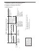
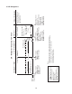
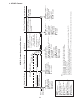

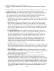
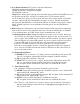
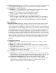
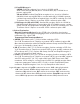
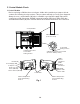
Table Of Contents

20
C. Control Module Check
1. Control Module
Before replacing a CM that does not show a visible defect and that you suspect is bad,
conduct the following check procedure. This procedure will help you verify your diagnosis.
Always choose a neutral white (W) wire to establish a good power supply and neutral
connection to CM. Check that 115VAC is present between CM Live In black (BK) wire
and CM Neutral white (W) wire. Conrm defrost and cabinet thermistors are connected.
Neutral (W)
Power Supply (BK)
Compressor (V)
Evaporator Fan
Motor (BK-SM)
Defrost Heater (BK-SM)
Control Dial
PRB 2
Defrost
Thermistor
PRB 1
Cabinet
Thermistor
Red LED
Yellow LED
Green LED
Fig. 1
2
Cabinet Temperature Control Dial
(shown in "OFF" position)
Cabinet Thermometer
(located on shelf)
Cabinet Temperature
Control Dial Setting
Position
Cabinet Temperature
Control Dial Setting
Position
Cabinet Temperature
Control Dial
Setting Position
Control Dial
Setting Position
Control Module