
Service Manual

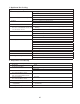
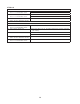
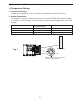
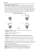
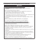
Table Of Contents

21
1a. Control Module LED Operation:
The control module has 3 LEDs that illuminate based on the status of the thermistors.
Red (R), Yellow (Y), and Green (G).
a) Warm Cabinet Thermistor - Power on: All 3 LEDs turn on for 2 sec. then turn off.
Next, yellow (Y) LED turns on for 10 sec.
b) Warm Cabinet Thermistor - Compressor energizes: Yellow (Y) LED turns off,
green (G) LED turns on (normal cooling cycle).
c) Cool Cabinet Thermistor - Cabinet temperature achieved.
Compressor de-energizes: Green (G) LED ashes (normal off cycle).
d) 2-min. Compressor ON/OFF Startup Delay - Yellow (Y) LED on.
e) Defrost Initiated or Defrost Thermistor Failure: Red (R) and green (G) LEDs turn on.
f) Control Dial placed in the "OFF" position:
Red (R), yellow (Y), and green (G) cycling.
g) Cabinet Thermistor Fault: Yellow (Y) and
green (G) LED ashing. Note: on cabinet
thermistor fault appliance cycles 5-min. on
5-min. off until cabinet thermistor connection
restored or cabinet thermistor replaced.
CONTROL MODULE LED OPERATION
LEDs
R Y G LED OPERATION
X
X 10-SEC. DELAY
X X
SYSTEM ON
X X
CTh SATISFIED; SYSTEM OFF
X X
2-MIN. ON/OFF DELAY
X
DEFROST/DTh FAULT
SYSTEM OFF
X
CTh FAULT
LED OPERATION LEGEND
CYCLING
FLASHING
ON
X OFF
2. Startup/Cool Down
At startup, CM displays a ash of the solid green, yellow, and red LEDs, then yellow LED
turns on for 10 sec. Yellow LED turns off and a solid green LED turns on (normal cooling
cycle). Unless 2-min. Comp delay timer is on. CTh Diagnosis: If green and yellow LEDs
ashing (CTh fault code), check CTh for continuity and good connection to CM. See "II.D.
Thermistor Check."
1) Check all wiring connections.
2) Be sure the power supply is connected to the electrical outlet.
3) Conrm the CTh is properly connected (no green and yellow LEDs ashing). A Solid
yellow LED turns on for 10 sec. at startup. After 10 sec. the yellow LED turns off and is
replaced by a solid green LED. During a 2-min. Comp delay, the yellow LED remains on.
If the green and yellow LED starts ashing, check CTh continuity. Replace as needed.
4) Check that Comp, ConFM, EvapFM, PH and MH (UF/WF) energize. If not check CTh
status. See "II.D. Thermistor Check." If CTh ohm reading is in proper range,
Comp, ConFM, PH (UF/WF) and MH (UF/WF); check for 115VAC at COMP violet (V)
to a neutral white (W) wire. If 115VAC is not present, replace CM. If 115VAC is present
and Comp energized and ConFM did not, check ConFM blades for binding and motor
winding continuity.
If PH (UF/WF) or MH (UF/WF) do not energize, check continuity, replace as needed.
EvapFM; Check for 115VAC at AUX 1 black-smooth (BK-SM) to neutral white (W).
If 115VAC is not present, replace CM. If115VAC is present, check EvapFM blades for
binding and motor winding continuity.