
Service Manual

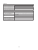
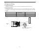
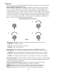
Table Of Contents
22
3. Defrost initiation
5) Manual Defrost Check: Unplug the appliance from the electrical outlet, then move the
CTCD to the off position. Plug appliance back into the electrical outlet. The CM green,
yellow, and red LED turn on. Rotate the CTCD clockwise to position 4 (green and red
LED turn off, yellow LED remains on), move Counter-clockwise to position 2(yellow
LED turns off and red LED turns on), move back clockwise to position8 (red LED
remains on and green LED turns on). Defrost initiates. Note: Once the CTCD is on the
number position, conrm the appropriate LED turns on. If not, move the CTCD back
and forth until the LED turns on. Once on, move to the next position. After attempting
CTCD sequence several times and defrost still not initiated, wait 1 to 2min. and repeat
process. If defrost cycle still not activated, replace CM as needed.
6) UR/WR Defrost Check: Conrm EvapFM remains energized.
7) SR and UF/WF Defrost Check: Conrm Comp, ConFM, EvapFM, PH (UF/WF),
and MH (UF/WF) de-energizes. If not, for Comp and ConFM, check for 115VAC at
COMP violet (V) wire to neutral white (W) wire and for EvapFM check for 115VAC at
AUX1black/smooth (BK/SM) to neutral white (W) wire. If 115VAC is present, replace
CM. Conrm DH energizes. If not, check for 115VAC at AUX 2 black (BK) wire to neutral
white (W) wire. If 115VAC is not present, replace CM.
4. Defrost Termination
8) Check that all components restart after defrost termination.
a) UR/WR: DTh warms to 45°F (7.2°C). Conrm continuity of DTh.
See "II.D. Thermistor Check." Replace as needed. If DTh conrmed, replace CM.
b) SR: DTh warms to 46°F (7.7°C). DH de-energizes. Conrm continuity of DTh. See
"II.D. Thermistor Check." Replace as needed. If DTh is good and DH continues after
DTh achieves 46°F (7.7°C), replace CM.
c) UF/WF: DTh warms to 55°F (12.7°C). DH de-energizes. Conrm continuity of DTh.
See "II.D. Thermistor Check." Replace as needed. If DTh is good and DH continues
after DTh achieves 55°F (12.7°C), replace CM. 3-min. DOT starts. All components
are de-energized during DOT. 3-min. DOT terminates, Comp and ConFM energize.
If not, check for 115VAC at CM Neutral white (W) wire to CM Comp violet (V) wire.
If 115VAC is not present, replace CM. Once Comp energizes, 3-min. EvapFM delay
timer starts. EvapFM energizes when DT achieves 10°F (-12.2°C) or the EvapFM
delay timer terminates. Whichever comes rst. If EvapFM does not energize, check
for 115VAC at CM Neutral white (W) wire to CM Aux 1 black-smooth (BK-SM) wire.
If 115VAC is not present, replace CM.
Legend: Comp–compressor; ConFM–condenser fan motor; CM–control module;
CTCD–cabinet temperature control dial; CTh–cabinet thermistor;
DH–defrost heater; DOT–drip off time; DTh–defrost thermistor;
EvapFM–evaporator fan motors, MH–mullion heater; PH–perimeter heater