Operator’s Manual Model 250WFG MIG/TIG/ARC Welder MIG/TIG/ARC Welder WARNING: Do not assemble, install, or operate this equipment without reading ALL of this manual and the safety precautions and warnings illustrated in this manual. KDAR Company 1 Mulch Lane St. Louis, MO 63044 Tel: (314) 692-8555 Fax: (314) 692-8578 Web Site: www.hotmaxtorches.
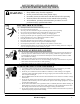
SAFETY PRECAUTIONS AND WARNINGS PLEASE READ BEFORE USING EQUIPMENT WARNING Keep children away from this equipment Protect yourself and others from possible injury Pacemaker wearers should consult with their doctor before operating Read and follow all instructions in this manual before operating All installation, operation, and maintenance procedures are to be performed only by qualified individuals ELECTRIC SHOCK CAN KILL.
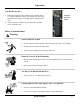
WELDING SPARKS CAN CAUSE INJURY, FIRE, OR EXPLOSION Remove all flammable materials from the welding area Always have a charged fire extinguisher available in the welding area When not welding make sure the welding tip is not grounded, this causes a heat build up and possible fire Avoid welding near hydraulic lines, fuel lines, electrical cords, air hoses, or welding guns and cables Sparks and hot metal fly out from the work area when welding, wear approved safety glasses with side shields under a
NOISE CAN DAMAGE HEARING Prolonged noise exposure from welding equipment can cause damage if levels of noise exceed the OSHA standards Wear approved hearing protectors Warn other workers nearby of the high noise level and hazard CALIFORNIA PROPOSITION 65 WARNINGS Welding or cutting equipment produces fumes or gases which contain chemicals known to the State of California to cause birth defects, and in some cases, cancer. (California Health and Safety Code Section 25249.5 et seq.
Specifications Rated Input Rated Output - Arc Rated Output - MIG Rated Output - TIG Duty Cycle - Arc Duty Cycle - MIG Duty Cycle - TIG 50 Amps @ 220 Volts, 60 Hz, Single Phase 30- 230 Amps, 21.2 to 29.2 Volts DC 50 - 250 Amps, 16.5 to 26.5 Volts DC 20 - 230 Amps, 10.8 to 19.
Installation/Setup Safety Considerations Warning Improper Lifting Techniques Can Cause Injury This unit requires two people when being lifted. Always use proper lifting techniques.
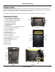
Installation/Setup Selecting A Location The 250WFG welder should be placed where clean cool air can easily flow through the vents in the front of the unit. Dirt and dust can be drawn into the unit resulting in excessive operating temperatures and shutdowns, therefore, dirt and dust around the unit should be kept to a minimum. The 250WFG welder should be placed on a stable, level surface suitable to hold the unit’s weight. Components and Controls 1. Output Voltage Adjust Knob (MIG) 2.
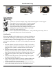
Installation/Setup Warning Always unplug the welder before connecting or disconnecting accessories. Unit Assembly 1. With something to prevent scratching under the unit, tip the welder forward onto its face. 2. Using the six 6mm x 12mm bolts and 6mm lock washers, attach the tank deck to the welder as shown in figure 5. 3. Slide the wheel axle through the two holes in the tank deck, slide one washer on each end followed by a 10” wheel and a second washer.
Installation/Setup 5 7 3 6 Figure 8 Figure 9 5 Figure 10 Gas Connection Warning Cylinder can explode if damaged. Keep cylinder chained upright to a secure support. Keep cylinder away from areas where it could be damaged. Never lift or move the welder with the cylinder attached. Do not let the welding electrode touch the cylinder. Keep the cylinder away from welding or other live circuits. Shielding Gas may be harmful to health or cause death. Turn off gas supply when not in use.
Operation Gas Hook Up (cont.) 7. Reopen the regulator valve until the flow indicator shows 15 L/min (initial flow setting). The setting may need to be adjusted by the operator to compensate for welding conditions. 8. Always close the cylinder valve and open the regulator valve when not in use. Properly Secured Tank Safety Considerations Warning Electric Shock Can Kill Do not touch live electrical parts of the electrode with skin or wet clothing. Insulate yourself from work and ground.
Operation Controls—Arc 1. Power Level (Dial 3, Fugure 13)—Sets the power level from 30-230 Amps. Power level can be adjusted while welding. 2. Welding Method Selector (Switch 4, Figure 13)— Set rocker switch to the left setting for MIG welding. On/ Off Controls—MIG 1. Output Voltage Control (Dial 1, Figure 13)—The Hot Max infinite setting output voltage control knob adjusts to any setting from 13.7 to 28.5 volts. 2. Speed Control (Dial 2, Figure 13)—Controls the wire feed speed. 3.
Operation Loading & Feeding Wire—MIG 4 Note: Always tur n power off when wor king inside the welder enclosure. 5 Note: It is a good idea to take the contact tip off of the gun prior to feeding the wire. 8” or 12” Diameter Spool 1. Remove the plastic tensioning cover (1), load spool with wire coming from under the spool (for 8” spool put spool spacer on first). Replace plastic tensioning cover (tighten enough so the spool does not turn freely). 2.
Operation Changing Drive Roll 1 2 The drive rollers have two grooves with the size of the groove etched in the corresponding side of the drive roller. The welder is shipped set up for .040 (1.0 mm). 1. Turn power off and unplug the welder. 2. Open the wire drive compartment door, release the spring loaded tension arm (1) by flipping it down and lift the left and right idle arm (2). 3. Remove the drive roller retention covers by turning them counter-clockwise (3). 4.
Maintenance Warning Electrical Shock Can Kill Disconnect from the input power source prior to working inside the welder. Allow only qualified personnel to do maintenance and trouble shooting. General Maintenance Gun Cable (cont.) Power Supply Compartment 3. Flex the cable over its entire length and blow air through again. Repeat flexing the cable and blowing air through until no dirt comes out. The Hot Max 250WFG does not have any serviceable parts inside the power supply compartment.
Troubleshooting Warning Most components of the 250WFG welder are not serviceable by the operator and should only be serviced by a qualified repair technician. Unauthorized repairs to these units may result in danger to the operator and will void the factory warranty. For your safety, please follow all safety precautions found throughout this manual. Problem Possible Cause Nothing happens when the trigger is pulled; no wire feed, weld output or gas flow. Fan is not operating. 1.
Troubleshooting Problem Possible Cause Arc is unstable—Poor starting 1. Check to insure proper input voltage to the welder. Check the plug to make sure the unit was wired correctly for 230V. 2. Check electrode polarity to make sure it is correct for the process being used. 3. Check tip/electrode for proper size and damage; replace if necessary. 4. Insure proper gas flow for the process. 5. Make sure the connections for the ground cable are correct. 6.
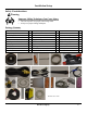
Additional Accessories/Replacement Parts for 250WFG Model 23242 36V Heated Regulator/Flow Meter Model 23241 250WFG Spool Gun 250WFG Replacement Contact Tips Model 23247 - .025” Contact Tip Model 23248 - .030” Contact Tip Model 23249 - .035” Contact Tip Model 23250 - .040” Contact Tip Model 23251 - .
Additional Accessories/Replacement Parts for 250WFG Model 23245 250WFG Replacement Electrode Holder Model 23243 250WFG Replacement MIG Gun Model 23258 250WFG Replacement Ground Clamp Model 23244 250WFG Replacement TIG Gun Model 23240 250WFG Replacement TIG Foot Pedal Model 23201 Replacement Standard Regulator for Argon/CO2 Replacement Drive Wheels Model 23253 - .030”/.040” Drive Wheel Model 23254 - .040”/.
Warranty KDAR Company, and its affiliates, warrants that all welders covered under this warranty is free from defects in material and workmanship for one year from the date of purchase. KDAR also warrants that all guns, hoses and ground clamp assemblies are free from defects in material and workmanship for 90 days from the date of purchase. This warranty is extended to the original purchaser who uses the product in a consumer application (personal, residential or household usage).
KDAR Company 1 Mulch Lane St. Louis, MO 63044 Phone: (314) 692-8555 Fax: (314) 692-8578 Rev.