GE Consumer & Industrial Appliances Installation Instructions Built-In Dishwasher If you have questions, call 800.GE.CARES (800.432.2737) or visit our website at: GEAppliances.com In Canada, call 1.800.561.3344 or visit www.GEAppliances.ca BEFORE YOU BEGIN IMPORTANT – The dishwasher MUST be Read these instructions completely and carefully. IMPORTANT – Observe all governing codes and ordinances. • Note to Installer – Be sure to leave these instructions for the consumer and local inspector’s use.
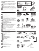
PARTS SUPPLIED IN INSTALLATION PACKAGE: Screw Kit ■ Two 8-18 x 5/8" Phillips-head wood screws ■ Junction box cover and #10 hex head screw ■ Drain hose (78" long) and hose clamp ■ Cord protector (Power Cord Models Only) ■ Conversion leads (Power Cord Models Only) ■ Literature, product samples and/or coupons #10 Hex Head Junction Box Screw 1/2" long #8 Phillips-Head Wood Screws 5/8" long 78" Drain Hose Cord Protector (Power Cord Models Only) Hose Clamp Conversion Leads (Power Cord Models Only) MATERI
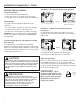
Installation Preparation – Enclosure PREPARE DISHWASHER ENCLOSURE WARNING To reduce the risk of shock, fire, or injury to persons, the installer must ensure that the dishwasher is completely enclosed at the time of installation. ADVERTENCIA #282 French • The dishwasher must be installed no more than 10 feet from sink for proper drainage. • The dishwasher must be fully enclosed on the top, sides and back. • The dishwasher must not support any part of the enclosure.
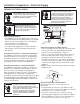
Installation Preparation – Drain PREPARE DRAIN PLUMBING METHOD 1 – Air Gap with Waste Tee or Disposer Drain Requirements • Follow local codes and ordinances. • Drain hose must not exceed 10 feet in length. • A high drain loop or air gap is required. See below. Drain Method The type of drain installation depends on the following: • Do local codes or ordinances require an air gap? • Is waste tee less than 18" above the floor? If the answer to either question is YES, an air gap (Method 1) must be used.
Installation Preparation – Electrical Supply PREPARE ELECTRICAL WIRING WARNING FOR PERSONAL SAFETY: Remove house fuse or open circuit breaker before beginning installation. Do not use an extension cord or adapter plug with this appliance. ADVERTENCIA #282 French ADVERTENCIA PARA SEGURIDAD PERSONAL: Retire el fusible de la casa o abra el interruptor de circuitos antes de empezar la instalación. No use un cable de extensión o enchufe adaptador con este aparato.
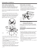
Installation Preparation – Hot Water Supply Prepare Hot Water Supply Hot Water Line • The line may enter from either side, rear or floor within the shaded area shown in Figure F. • The line may pass through the same hole as the electrical cable and drain hose, or cut an additional 1-1/2" diameter hole to accommodate the water line. If a power cord with plug is used, the water line must not pass through the power cord hole. 1-1/2" Dia.
Dishwasher Installation STEP 3: REMOVE WOOD BASE CAUTION Do not remove the wood base until you are ready to install the dishwasher. The dishwasher will tip over when the door is opened if the base is removed. PRECAUCIÓN No retire la base de madera hasta que esté listo para instalar la lavadora de platos. Cuando la puerta se abra, la lavadora de platos se inclinará si la base se retira. STEP 1: PREPARATION Locate the items in the installation package and set them aside for use in the listed steps.
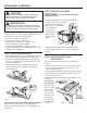
Dishwasher Installation STEP 5: INSTALL POWER CORD STEP 6: INSTALL 90° ELBOW Skip this step if the dishwasher will be permanently connected to the house electrical system or has a factory-installed power cord. • Wrap a 90° elbow with thread seal tape. • Thead the 90° elbow into the water valve. • Do not overtighten the elbow; water valve bracket could bend or the valve fitting could break. • Position the end of the elbow to face the rear of the dishwasher.
Dishwasher Installation Note: The drain hose supplied with the dishwasher is approximately 78" long. If a longer hose is needed, a 10-foot-long hose may be purchased from an authorized GE appliance dealer. The 10-foot-long hose is part number GPF10S. Strain Relief Figure L Drain Hose Hose Stop Do not use this port if present STEP 9: insert drain hose AND POWER CORD, IF USED, through cabinet • Upright the dishwasher and position it in front of the cabinet opening.
Dishwasher Installation STEP 11: S LIDE DISHWASHER INTO CABINET IMPORTANT – Do not push against the front panel with knees. Damage will occur. • Grasp the sides of the front panel and slide the dishwasher into the opening a few inches at a time. Pull the drain hose and power cord, if equipped, through the holes in the adjacent cabinet while sliding the dishwasher into position.
Dishwasher Installation STEP 13: fasten DISHWASHER to underside of countertop or sides of cabinet In this step you will need the two 5/8" Phillips-head wood screws set aside in Step 1. IMPORTANT – Dishwasher must be centered in cabinet opening. Interference with cabinets or countertop will cause leaks and damage to the door panel and/or control panel. STEP 14: connect water supply Connect the water supply line to the 90° elbow installed in Step 6.
Dishwasher Installation STEP 15: CONNECT DRAIN LINE Method 1 – Air gap with waste tee or disposer The molded end of the drain hose will fit 5/8" through 1" diameter inlet ports on the air gap, waste tee or disposer. • Determine the size of the inlet port • Cut the drain hose connector on the marked line, if required, to fit the inlet port.
Dishwasher Installation STEP 16: CONNECT POWER SUPPLY STEP 17: install junction box cover If a power cord with plug is already installed, proceed to Step 17. If junction box cover is already installed, skip to Step 18. If the dishwasher came with a factory-installed power cord and you want to convert it to a permanent connection, refer to the instructions on page 16. In this step you will need the junction box cover and the #10 hex-head screw from the screw kit set aside in Step 1.
Dishwasher Installation STEP 19: dishwasher wet test checklist ■ Turn on power supply or if power cord is used, plug it into the wall outlet. ■ Latch dishwasher door. ■ For electronic dishwashers, select the normal WASH cycle and press the start pad one time. – Check the electrical connection to the water valve. The red electrical connector should be plugged into the dishwasher water valve. If it is not plugged in, turn off electrical power to the dishwasher.
Dishwasher Installation STEP 20: replace access panel and toekick In this step you will need the panels and the two screws set aside in Step 4. There are two types of screws used. The 8-32 x 1/4" screws are used at the top of the access panel and should still be in place. The 10-16 x 3/8" screws are used at the bottom of the access panel and secure both the access panel and toekick. STEP 21: LITERATURE ■ Leave the Owners’ Manual, Installation Instructions, samples and/or coupons with consumer.
Appendix CONVERTING DISHWASHER WITH FACTORYEQUIPPED POWER CORD TO A PERMANENT CONNECTION This procedure requires the conversion leads set aside in Step 1. • Make sure the power cord for the dishwasher is unplugged from the wall outlet. • Remove screw from junction box cover and remove cover if present. • Disconnect the three power cord conductors from the dishwasher harness. See Figure BB. • Remove and discard the power cord.
Appareils ménagers GE Consumer and Industrial Instructions d’installation Lave-vaisselle encastré Pour toute question, composez le 1.800.561.3344 ou visitez notre site Web : www.electromenagersge.ca ARRÊT AVANT DE COMMENCER Veuillez lire attentivement toutes les directives qui suivent. IMPORTANT – Observez tous les codes et ordonnances en vigueur. • Note à l’installateur – Veuillez laisser les présentes directives au consommateur pour l’inspecteur local.
PIÈCES FOURNIES : Ensemble de Vis ■ Deux vis à bois Phillips n° 8-18 x 15,8 mm (5/8 po) ■ Couvercle de la boîte de jonction et vis à tête hexagonale n° 10 ■ Boyau de vidange (198 cm [78 po] de long) et collier ■ Protège-cordon d’alimentation (modèles dotés d’un cordon d’alimentation seulement) ■ Fils pour la conversion (modèles dotés d’un cordon d’alimentation seulement) ■ Documentation, échantillons et(ou) bons Couvercle de la boîte de jonction Boyau de vidange de 198 cm (78 po) Fils pour la Protège-co
Préparation pour l'installation – Ouverture dans les armoires PRÉPARATION DE L'OUVERTURE DANS LES ARMOIRES AVERTISSEMENT Pour réduire les risques de choc électrique, d'incendie ou de blessures, l'installateur doit s'assurer que le lavevaisselle est complètement encastré au moment de l'installation.
Préparation pour l’installation – Vidange PRÉPARATION DE LA PLOMBERIE POUR LA VIDANGE Exigences relatives au système de vidange • Veuillez observer les ordonnances et les codes locaux en vigueur. • Le boyau de vidange doit avoir une longueur maximale de 3 mètres (10 pieds). • Il faut prévoir une boucle de vidange élevée ou l’installation d’une coupure anti-refoulement. Voir ci-dessous.
Préparation pour l’installation – Alimentation électrique PRÉPARATION DU CÂBLAGE ÉLECTRIQUE AVERTISSEMENT POUR VOTRE SÉCURITÉ PERSONNELLE : Enlevez le fusible ou déclenchez le disjoncteur au panneau de distribution principal avant de commencer l'installation. N'utilisez pas une rallonge électrique ou un adaptateur de fiche avec cet appareil.
Préparation pour l’installation – Alimentation en eau chaude PRÉPARATION DE L’ALIMENTATION EN EAU CHAUDE Conduite d’eau chaude • La conduite peut entrer du côté gauche, du côté droit, de l’arrière ou du plancher dans la partie ombrée indiquée dans la Figure F. • La conduite peut passer par le même trou que le câble électrique et le boyau de vidange, ou vous pouvez percer un trou supplémentaire de 3,8 cm (1 1/2 po) de diamètre pour le passage de la conduite d’eau.
Installation du lave-vaisselle ÉTAPE 3 : ENLÈVEMENT DE LA BASE DE BOIS ATTENTION N’enlevez pas la base de bois avant d’être prêt à installer le lave-vaisselle. Si vous enlevez la base de bois, le lavevaisselle pourrait basculer lorsque vous ouvrez la porte. ÉTAPE 1 : PRÉPARATION Prenez les pièces fournies dans l’emballage et mettez-les de côté en vue de les utiliser au cours des étapes indiquées ci-dessous.
Installation du lave-vaisselle ÉTAPE 5 : I NSTALLATION DU CORDON D’ALIMENTATION Sautez cette étape si le lave-vaisselle est branché de façon permanente au circuit électrique de la résidence ou s’il est doté d’un cordon d’alimentation installé à l’usine. Au cours de cette étape, vous aurez besoin du couvercle de la boîte de jonction et de la vis à tête hexagonale n° 10 x 12,7 m (1/2 po) provenant de l’ensemble de vis que vous avez mis de côté à l’étape 1.
Dishwasher Installation Remarque : Le boyau de vidange fourni avec le lave-vaisselle mesure environ 2 mètres (78 po) de longueur. Si vous avez besoin d’un boyau plus long, vous pouvez vous procurer un boyau de 3 mètres (10 pieds) auprès d’un détaillant autorisé d’électroménagers GE. Le numéro de pièce du boyau de 3 mètres de long est le GPF10S.
Installation du lave-vaisselle ÉTAPE 11 : I NSTALLATION DU LAVEVAISSELLE DANS L’OUVERTURE ÉTAPE 12 : MISE DE NIVEAU DU LAVEVAISSELLE IMPORTANT – Ne poussez pas sur le IMPORTANT – Le lave-vaisselle doit être de panneau avant avec vos genoux. Vous pourriez endommager l’appareil. • Saisissez le panneau avant de l’appareil par les côtés et faites glisser le lave-vaisselle dans l’ouverture de quelques centimètres ou pouces à la fois.
Installation du lave-vaisselle ÉTAPE 13 : F IXATION DU LAVE-VAISSELLE AU-DESSOUS DU COMPTOIR OU AUX CÔTÉS DES ARMOIRES Au cours de cette étape, vous aurez besoin des deux vis à bois Phillips de 15,8 mm (5/8 po) mises de côté à l’étape 1. IMPORTANT – Le lave-vaisselle doit être bien centré dans l’ouverture. Si la porte frotte contre les armoires ou le comptoir, cela pourrait provoquer des fuites et endommager le panneau de la porte et(ou) le tableau de commande.
Dishwasher Installation ÉTAPE 15 : R ACCORDEMENT DU BOYAU DE VIDANGE L’extrémité moulée du boyau de vidange est conçue pour s’installer sur l’orifice d’entrée d’un diamètre variant entre 15,8 mm (5/8 po) et 25,4 mm (1 po) de la coupure anti-refoulement, du raccord en T ou du broyeur à déchets. • Mesurez le diamètre de l’orifice d’entrée. • Coupez le raccord du boyau de vidange à l’endroit indiqué, au besoin, pour qu’il soit bien adapté à l’orifice d’entrée.
Installation du lave-vaisselle ÉTAPE 16 : BRANCHEMENT DE L’ALIMENTATION ÉLECTRIQUE ÉTAPE 17 : INSTALLATION DU COUVERCLE DE LA BOÎTE DE JONCTION Si un cordon d’alimentation pourvu d’une fiche est déjà installé sur l’appareil, passez à l’étape 17. Si le couvercle de la boîte de jonction est déjà installé, passez à l’étape 18.
Installation du lave-vaisselle ÉTAPE 19 : L ISTE DE CONTRÔLE DE L’ESSAI DU LAVE-VAISSELLE AVEC DE L’EAU ■ Rétablissez l’alimentation électrique ou si l’appareil est doté d’un cordon d’alimentation, branchez-le dans la prise de courant murale. ■ Verrouillez la porte du lave-vaisselle. ■ Dans le cas des modèles électroniques, sélectionnez le programme NORMAL WASH (Saleté normale) et appuyez une fois sur la touche START (Mise en marche). Cycles – Vérifiez le raccordement électrique de l’électrovanne.
Installation du lave-vaisselle ÉTAPE 20 : R ÉINSTALLATION DU PANNEAU D’ACCÈS ET DU PANNEAU INFÉRIEUR Au cours de cette étape, vous aurez besoin des panneaux et des deux vis mis de côté à l’étape 4. Deux types de vis sont utilisés. Les vis n° 8-32 x 6,3 mm (1/4 po) sont utilisées à la partie supérieure du panneau d’accès et doivent y être laissées. Les vis n° 10-16 x 9,5 mm (3/8 po) sont utilisées à la partie inférieure du panneau d’accès pour fixer en place le panneau d’accès et le panneau inférieur.
Annexe TRANSFORMATION D’UN LAVE-VAISSELLE DOTÉ D’UN CORDON D’ALIMENTATION INSTALLÉ À L’USINE EN VUE D’UN BRANCHEMENT PERMANENT Pour accomplir cette procédure, vous avez besoin des fils pour la conversion mis de côté à l’étape 1. • Assurez-vous que le cordon d’alimentation du lave-vaisselle est débranché de la prise de courant murale. • Enlevez la vis du couvercle de la boîte de jonction, puis enlevez le couvercle, s’il y a lieu.