Mounting Instructions Digital Torque Transducer T12 A1979−10.
T12 Contents Page Contents Safety instructions . . . . . . . . . . . . . . . . . . . . . . . . . . . . . . . . . . . . . . . . . . . . . . 5 1 Markings used . . . . . . . . . . . . . . . . . . . . . . . . . . . . . . . . . . . . . . . . . . . . . . . 1.1 Symbols on the transducer and / or Stator . . . . . . . . . . . . . . . . . . . 1.2 The markings used in this document . . . . . . . . . . . . . . . . . . . . . . . . 9 9 10 2 Scope of supply . . . . . . . . . . . . . . . . . . . . . . . . . . .
T12 9.3 9.4 Connector pin assignment . . . . . . . . . . . . . . . . . . . . . . . . . . . . . . . . Supply voltage . . . . . . . . . . . . . . . . . . . . . . . . . . . . . . . . . . . . . . . . . . 39 43 10 Shunt signal . . . . . . . . . . . . . . . . . . . . . . . . . . . . . . . . . . . . . . . . . . . . . . . . . 45 11 Load-carrying capacity . . . . . . . . . . . . . . . . . . . . . . . . . . . . . . . . . . . . . . . 46 12 TEDS . . . . . . . . . . . . . . . . . . . . . . . . . . . . . . . .
T12 Safety instructions FCC Compliance & Advisory Statement for Option 7, Code U This device complies with Part 15 of the FCC Rules. Operation is subject to the following two conditions: (1) this device may not cause harmful interference, and (2) this device must accept any interference received, including interference that may cause undesired operation. The FCC identifier or the unique identifier, as appropriate, must be displayed on the device.
T12 Cet appareil est conforme aux normes d’exemption de licence RSS d’Industry Canada. Son fonctionnement est soumis aux deux conditions suivantes : (1) cet appareil ne doit pas causer d’interférence et (2) cet appareil doit accepter toute interférence, notamment les interférences qui peuvent affecter son fonctionnement. NOTE Any changes or modification not expressly approved by the party responsible for compliance could void the user’s authority to operate the device.
T12 Use as a machine element The torque flange can be used as a machine element. When used in this manner, it must be noted that, to favor greater sensitivity, the transducer is not designed with the safety factors usual in mechanical engineering. Please refer here to the section “Load carrying capacity limits” and to the specifications.
T12 or destroyed by non-designated use of the transducer or by non-compliance with the mounting and operating instructions, these safety instructions or any other applicable safety regulations (BG safety and accident prevention regulations), when using the transducers. Transducers can break, particularly in the case of overloading. The breakage of a transducer can also cause damage to property or injury to persons in the vicinity of the transducer.
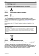
T12 1 Markings used 1.1 Symbols on the transducer and / or Stator Symbol: Meaning: Read and note the data in this manual Symbol: Meaning: CE mark The CE mark enables the manufacturer to guarantee that the product complies with the requirements of the relevant EC directives (the Declaration of Conformity can be found on the HBM website at www.hbm.com under HBMdoc). Lable example with FCC ID and IC number. Location on the stator of the device.
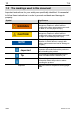
T12 1.2 The markings used in this document Important instructions for your safety are specifically identified. It is essential to follow these instructions in order to prevent accidents and damage to property. Symbol Significance WARNING This marking warns of a potentially dangerous situation in which failure to comply with safety requirements can result in death or serious physical injury.
T12 2 Scope of supply Digital torque transducer (rotor and stator) T12 mounting instructions T12 system CD Mounting kit Manufacturing certificate Tape wound core (toroidal core) only with Option 9, Code U Tape wound core (toroidal core) only with Option 9, Code U Optional: − A rotational speed measuring system, comprising an optical rotational speed sensor and a rotational speed kit (slotted disc, screwdriver, threadlocker, screws) − Protection against contact − A mounted coupling 3
4 T12 Application The T12 digital torque transducer acquires static and dynamic torque at stationary or rotating shafts, determines the rotational speed or angle of rotation while specifying the direction of rotation, and calculates the power.
T12 5 Signal flow Low pass LP1: 0.05 Hz to 4000 Hz Low pass LP2: 0.05 Hz to 100 Hz Low pass LP: 0.1 Hz to 80 Hz Fig. 4.1: Signal flow diagram The torque and the temperature signal are already digitized in the rotor and transmission is noise-free. , scaled (2-point scaling) and The torque signal can be zeroed filtered via two low passes (LP1 and LP2). A further scaling of the frequency output and the analog output is then possible. Important Scaling at position (see Fig. 4.
T12 For settings over 100 Hz (torque low-pass filter 1 only), phase delay compensation is run for the angle of rotation signal. This ensures that torque and angle of rotation values that are measured simultaneously are also output simultaneously. Two pulse strings, offset by 90, are also available as RS422-compatible signals for rotational speed and angle of rotation. 6 Structure and mode of operation The torque transducer comprises two separate parts: the rotor and the stator.
T12 Side A Side B Transmitter head Rotor Stator Slotted disc (option) Rotational speed sensor (option) Housing Fig. 5.1: Mechanical structure, exploded view A1979−10.
7 T12 Mechanical installation 7.1 Important precautions during installation NOTE A torque flange is a precision measuring element and therefore needs careful handling. Dropping or knocking the transducer may cause permanent damage. Make sure that the transducer cannot be overloaded, including while it is being mounted. Handle the transducer with care.
T12 Important Even if the unit is installed correctly, the zero point adjustment made at the factory can shift by up to approx. 3% of the sensitivity. If this value is exceeded, we advise you to check the mounting conditions. If the residual zero offset when the unit is removed is greater than 1% of the sensitivity, please send the transducer back to the Darmstadt factory for testing. 7.2 Conditions on site The T12 torque transducer is protected to IP54 according to EN 60529.
T12 7.4 Installing the slotted disc (rotational speed measuring system only) To prevent damage to the rotational speed measuring system’s slotted disc during transportation, it is not mounted on the rotor. The customer must attach it to the mounting ring before installing the rotor in the shaft train. The mounting ring and the associated rotational speed sensor are already mounted at the factory.
T12 7.5 Installing the rotor Tip Usually the rotor type plate is no longer visible after installation. This is why we include with the rotor additional stickers with the important characteristics, which you can attach to the stator or any other relevant test-bench components. You can then refer to them whenever there is anything you wish to know, such as the shunt signal.
T12 1. Prior to installation, clean the plane faces of the transducer flange and the counter flange. For safe torque transfer, the faces must be clean and free from grease. Use a piece of cloth or paper soaked in solvent. When cleaning, make sure that you do not damage the transmitter coils. 2. For the flange B screw connection, use hexagon socket screws DIN EN ISO 4762 of property class 10.9 (measuring ranges 3 kN@m to 10 kN@m: 12.
T12 Important Use a threadlocker (medium strength, e.g. LOCTITE) to glue the screws into the counter thread to exclude prestressing loss due to screw slackening, in the event of alternating loads. NOTE Comply with the maximum thread reach as per Table 6.1. Otherwise significant measurement errors may result from torque shunt, or the transducer may be damaged.
T12 Important Use a threadlocker (medium strength, e.g. LOCTITE) to glue the connecting screws into the counter thread. 1. Remove the side cover plates on the stator housing (see Fig. 6.4.) Cover plate Cover plate Fig. 6.4: Cover plates on the stator housing 2. Only for measuring ranges 500 N@m to 3 kN@m and subsequently ordered protection against contact: some of the tapped holes for the locking screws are covered by attached film.
T12 Threaded pin Fig. 6.5: Cut out the film 3. For 5 kN@m and 10 kN@m measuring ranges only: remove the threaded pins from the tapped holes on both sides of the stator. Screw the spacing bolt into the tapped hole on the side of the rotational speed sensor (see Fig. 6.6). Threaded pin Spacing bolt 1 2 Fig. 6.6: Fit the spacing bolt (for 5 kN@m and 10 kN@m only) A1979−10.
T12 4. Screw the cover plate onto the side parts (screws with hexagon socket 2 a.f.; tightening torque MA = 1 N@m). Note that the cover plate with cutouts must be fitted onto the side with countersunk holes! (see Fig. 6.7). Side part Cover plate with holes Cover plate with cutouts 2 a.f. Countersunk hole Fig. 6.
T12 Fig. 6.8: Angled cover plates (5 kN@m and 10 kN@m measuring ranges) 5. Attach each of the side parts to the stator housing with two M6x25 hexagon socket screws (5 a.f.). Hand-tighten the screws. 6. Screw the side parts together at the top, by hand (two M6x30 hexagon socket screws; 5 a.f.). A1979−10.
T12 M6 x 30 M6 x 25 M6 x 25 Fig. 6.9: Fit the protection against contact halves 7. Align the protection against contact in such a way that its end face is parallel to the stator housing. Locking screw (on both sides) Parallel surfaces Fig. 6.10: Check for parallelism HBM A1979−10.
T12 8. Now tighten all the screws with a tightening torque MA of 14 N@m. 9. Screw in the cover plate locking screws and tighten them at 2 N@m. 7.7 Installing the stator On delivery, the stator has already been installed and is ready for operation. There are four tapped holes on the base of the stator housing for mounting the stator. Externally, two with a metric M6 thread, internally, two with a UNF 1/4” thread (closed with a plastic threaded pin).
T12 A 11 6.6 B Section through the countersunk hole in the protection against contact Fig. 6.12: Supporting the stator with an angle bracket (5 kN@m and 10 kN@m) 7.7.1 Preparing with the mounting kit (included among the items supplied) The supplied mounting kit contains self-adhesive spacers, to make it easier for you to align the stator to the rotor. Use the spacers to align the rotor and the stator radially and axially. Remove the protective film Fig. 6.
T12 Radial alignment with spacers The spacers should preferably be attached to the transmitter head, offset by 90, as shown in Fig. 6.14. If your stator is equipped with a rotational speed measuring system, you must either shorten the spacers to an appropriate length or attach them slightly offset, next to the rotational speed measuring system. 90 Spacers Fig. 6.14: Radial position of the spacers Axial alignment with spacers The red line on the spacers is used for axial alignment.
T12 Outer edge of transmitter head Red line Fig. 6.15: Axial position of the spacers Now remove the protective film and attach the spacers to the transmitter head, as described. Important Remove the spacers after installation. 7.7.2 Aligning the stator 1. Position the stator on an appropriate mounting base in the shaft train, so that there are sufficient opportunities for horizontal and vertical adjustments to be made. 2.
T12 Alignment line Transmitter rotor Spacer Fig. 6.16: Axial alignment to the rotor 6. Connect the power line (plug 1 or plug 3). Notice the LED to the right of plug 4. The stator is correctly aligned, when the LED successively flashes red for about 10 seconds flashes yellow for about 10 seconds then stays permanently green (CAN Bus) or yellow or green (PROFIBUS). When data are being exchanged via the CAN Bus or the PROFIBUS, the LED flashes green.
T12 7.7.3 Stator installation over the protection against contact (option) You can also axially flange the stator over the protection against contact (material: aluminum). Holes are provided in the side parts of the protection against contact for this purpose. For this mounting, we recommend M6 fillister-head screws with hexagon sockets in accordance with DIN EN ISO 4762; black/oiled/mtot=0.125, of the appropriate length. Fig. 6.17: Mounting holes in the protection against contact b2 b8 11 6.
T12 33 Fig. 6.18: Face-mounting on the engine shielding 7.8 Optical rotational speed/angle of rotation measuring system (option) As the stator with the optical rotational speed sensor only partially encloses the slotted disc, if there is sufficient space available for installation, you can subsequently move the stator tangentially over the ready-mounted rotor. For perfect measuring mode, the slotted disc of the rotational speed measuring system must rotate at a defined position in the sensor pickup. 7.8.
T12 Slotted disc Flange B Alignment lines Sensor pickup Fig. 6.19: Position of the slotted disc in the rotational speed sensor 7.8.2 Radial alignment The rotor axis and the optical axis of the rotational speed sensor must be along a line at right angles to the stator platform. A conical machined angle (or a colored mark) in the center of flange B and a vertical marker line on the sensor pickup serve as aids to orientation. HBM A1979−10.
T12 Centering point for aligning the rotor Marking Fig. 6.20: Alignment marks on rotor and stator Connect the power line (plug 1). Switch the LED display mode of the T12 Assistant to “optical rotational speed system” setting mode and turn the rotor. Notice the LED to the right of plug 4; this must stay green if the setting is correct (also see Chapter 8.3). Important Angle of rotation measurement is not suitable for static and quasi-static applications! A1979−10.
8 T12 LED status display The LED in the stator housing (next to device plug 4) has three display modes: standard (measuring mode), rotor clearance setting mode and setting mode for the optical rotational speed system. 8.
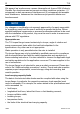
T12 9 Electrical connection 9.1 General information Detailed instructions for connecting the T12 to the CAN Bus or the PROFIBUS can be found in the “T12 CAN Bus/PROFIBUS” interface description (in pdf format) on the T12 system CD. To make the electrical connection between the torque transducer and the measuring amplifier, we recommend using shielded, low-capacitance measurement cables from HBM.
T12 3 loops Fig. 6.21: Installation Example If the core has to be removed for any purpose (e.g. for maintenance), it must be replaced on the cable. Use only wounded core (toroidal core) of the correct type. Type: Vitroperm R Model No.: T60006−22063W517 Size: external diameter x internal diameter x height = 63 x 50 x 25 The core should be placed as close as possible to the connector. However, prevent stress on the connector due to the extra weight of the cable.
T12 9.2 Shielding design The cable shield is connected in accordance with the Greenline concept. This encloses the measurement system (without the rotor) in a Faraday cage. It is important that the shield is laid flat on the housing ground at both ends of the cable. Any electromagnetic interference active here does not affect the measurement signal.
T12 Important If plug 1 is used to power the device a tape wound core (toroidal core) is neccessary to suppresse high frequencies in order to ensure compliance with FCC regulations NOTE Torque transducers are only intended for operation with a DC supply voltage (separated extra-low voltage), see page 43.
T12 Assignment for plug 2: Rotational speed measuring system with reference signal Plug pin Binder 423 device plug 6 7 1 8 4 2 3 5 Assignment Color code Sub-D plug pin 1 Rotational speed measurement signal (pulse string, 5 V1); 0) rd 12 2 Reference signal (1 pulse/rev., 5 V1)) bu 2 3 Rotational speed measurement signal (pulse string, 5 V); phase-shifted 90 ) gy 15 4 Reference signal (1 pulse/rev.
T12 Important If plug 3 is used to power the device a tape wound core (toroidal core) is neccessary to suppresse high frequencies in order to ensure compliance with FCC regulations. NOTE Do not use cable KAB149 to connect the voltage output signal at AP01i to ML01B of the MGCplus system! This cable is only suitable for connecting the frequency output signal. The analog output is designed as a monitoring output.
T12 Assignment for plug 5: CAN Bus; second device plug; A-coded, black washer Binder 713 (M12x1) 2 1 3 4 5 Plug pin Assignment Color code 1 Shield − 2 Not in use − 3 CAN ground − 4 CAN HIGH-dominant high wh 5 CAN LOW-dominant low bu Shielding connected to housing ground Top view Assignment for plug 5: PROFIBUS (option); B-coded, violet washer Binder 715 (M12x1) 2 1 3 4 5 Top view Plug pin Assignment 1 5 V (typ.
T12 voltage (24 V) can be up to 50 m long and in the nominal (rated) voltage range, 20 m long (see Accessories, page 88). If the permissible cable length is exceeded, you can feed the supply voltage in parallel over two connection cables (plugs 1 and 3). This enables you to double the permissible length. Alternatively, install an on-site power supply. If you feed the supply voltage through an unshielded cable, the cable must be twisted (interference suppression).
T12 10 Shunt signal The T12 torque transducer supplies a shunt signal, at either 50% or 10% of the nominal (rated) torque, as selected. Activate this function via the T12 Assistant or the shunt signal trigger on plug 1 or plug 3 (see Section 9.3). The last shunt selected in the T12 Assistant is then triggered. The internal signal conditioning may cause a delay in triggering of about 5 seconds.
11 T12 Load-carrying capacity Nominal (rated) torque can be exceeded statically up to the limit torque. If the nominal (rated) torque is exceeded, additional irregular loading is not permissible. This includes longitudinal forces, lateral forces and bending moments. Limit values can be found in the “Specifications” chapter (Chapter 15, page 56). Measuring dynamic torque The torque transducer is suitable for measuring static and dynamic torques.
T12 12 TEDS TEDS (Transducer Electronic Data Sheet) allows you to store the transducer data (characteristic values) in a chip, that can be read out by a connected measuring instrument.
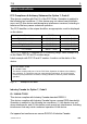
T12 Area 2: The base area (basic TEDS), to the configuration defined in standard IEEE1451.4. The transducer type, the manufacturer and the transducer serial number are contained here. Example: TEDS content of a T12/1 kN@m transducer TEDS Manufacturer Model Version letter Version number Serial number HBM (31) T12 (15) A 2 first position of stator ident no. 7 first position of stator ident no. Area 3: Data specified by the manufacturer and the user are contained in this area.
T12 Template: Frequency/Pulse Sensor Parameter Value Unit Explanation Transducer Electrical Signal Type Minimum Torque Pulse Sensor 0.000 Require d user rights ID N@m CAL Maximum Torque 1000 N@m CAL The physical measurand and unit are defined when the template is created, after which they cannot be changed.
T12 Template: High Level Voltage Sensor Parameter Value Unit Minimum Torque 0.
T12 Rotational speed/angle of rotation HBM has already written the “Frequency/Pulse Sensor” template for the rotational speed measurand. Template: Frequency/Pulse Sensor Parameter Value Unit Explanation Transducer Electrical Signal Type Minimum Frequency Pulse Sensor 0.000 Required user rights ID Hz CAL Maximum Frequency 108.000 k Hz CAL The physical measurand and unit are defined when the template is created, after which they cannot be changed.
T12 Template: Frequency/Pulse Sensor Parameter Value Measurement location ID 0 Transducer Electrical Signal Type Minimum Frequency Pulse Sensor 0.000E+000 Maximum Frequency 3.6E+002 Pulse Measurement Type Minimum Electrical Value Unit Required user rights USR ID degr ees degr ees CAL Count 0.
T12 Template: Frequency/Pulse Sensor Parameter Value Calibration Initials HBM or PTB Calibration Period (Days) 0 Measurement location ID 0 A1979−10.0 en Unit days Required user rights CAL CAL USR Explanation Initials of the calibrator or calibration laboratory concerned. Time before recalibration, calculated from the date specified under Calibration Date. Identification number for the measuring point. Can be assigned according to the application. Possible values: a number from 0 to 2047.
13 T12 Maintenance The T12 torque transducer without a rotational speed measuring system is maintenance-free. Cleaning the rotational speed measuring system During operation and depending on the ambient conditions, the slotted disc of the rotor and the associated optical system of the stator sensor can get dirty. This becomes noticeable, for example: in transducers with a reference pulse, when an increment error is displayed in the “Rotational speed signal” status in the T12 Assistant.
T12 14 Waste disposal and environmental protection All electrical and electronic products must be disposed of as hazardous waste. The correct disposal of old equipment prevents ecological damage and health hazards. Symbol: Meaning: Statutory waste disposal mark The electrical and electronic devices that bear this symbol are subject to the European waste electrical and electronic equipment directive 2002/96/EC.
15 T12 Specifications 15.1 Nominal (rated) torque 100 NVm to 1 kNVm Type Accuracy class Torque measuring system Nominal (rated) torque Mnom Nominal (rated) rotational speed nnom Option 3, code L 1) Option 3, code H 1) Non-linearity including hysteresis, related to nominal (rated) sensitivity Fieldbuses, frequency output 10 kHz/60 kHz For a max. torque in the range: between 0% of Mnom and 20% of Mnom > 20% of Mnom and 60% of Mnom > 60% of Mnom and 100% of Mnom Voltage output For a max.
T12 Nominal (rated) torque Mnom Output signal at torque = zero Frequency output 10 kHz/60 kHz Voltage output Nominal (rated) output signal Frequency output with positive nominal (rated) torque 10 kHz/60 kHz with negative nominal (rated) torque 10 kHz/60 kHz Voltage output with positive nominal (rated) torque with negative nominal (rated) torque Scaling range Frequency output/voltage output Resolution Frequency output 10 kHz/60 kHz Voltage output Residual ripple Voltage output Maximum modulation range 3)
T12 Nm kNm Rotational speed/angle of rotation measuring system Optical, using infrared light and a metallic slotted disc Mechanical increments number Positional tolerance of the increments mm Tolerance of the slot width mm Pulses per revolution (adjustable) number Pulse frequency at nominal (rated) rotational speed nnom Option 3, code L 4) kHz 4) Option 3, code H kHz Minimum rotational speed for sufficient pulse rpm quality Group delay s Hysteresis of direction of rotation reversal in the case of re
T12 Nominal (rated) torque Mnom Temperature effect per 10 K in the nominal (rated) temperature range on the output signal, related to the actual value of the signal span on the zero signal Residual ripple Angle of rotation Accuracy Resolution Correction of runtime deviation between torque LP1 and the angle of rotation for filter frequencies Nm kNm 100 200 500 1 % % mV < 0.03 < 0.03 <3 degrees degrees 1 (typ. 0.1) 0.
Fieldbuses CAN Bus Protocol Data rate Hardware bus link Baud rate Maximum line length Connector PROFIBUS DP Protocol Baud rate PROFIBUS Ident Number Input data , max. Output data, max. Diagnostic data Connector T12 − Meas. values/ s kBit/s m − − MBaud − bytes bytes bytes − Update rate 6) Configuration entries v2 v4 Meas.
T12 Nominal (rated) torque Mnom General information EMC Emission (per FCC 47 Part 15, Subpart C) Emission (per EN61326−1, Table 3) RFI voltage RFI power RFI field strength Immunity from interference (EN61326−1, Table A.
Nominal (rated) torque Mnom T12 Nm kNm 100 200 500 1 Mechanical values Torsional stiffness cT Torsion angle at Mnom Stiffness in the axial direction ca Stiffness in the radial direction cr Stiffness during the bending moment round a radial axis cb Maximum deflection at longitudinal limit force Additional max. radial deviation at lateral limit force Additional plumb/parallel deviation at limit bending moment (at j dB) Balance quality level per DIN ISO 1940 Max.
T12 15.2 Nominal (rated) torque 2 kNVm to 10 kNVm Type Accuracy class Torque measuring system Nominal (rated) torque Mnom Nominal (rated) rotational speed nnom Option 3, code L 1) Option 3, code H 1) Non-linearity including hysteresis, related to nominal (rated) sensitivity Fieldbuses, frequency output 10 kHz/60 kHz For a max. torque in the range: between 0% of Mnom and 20% of Mnom > 20% of Mnom and 60% of Mnom > 60% of Mnom and 100% of Mnom Voltage output For a max.
Nominal (rated) torque Mnom Output signal at torque = zero Frequency output 10 kHz/60 kHz Voltage output Nominal (rated) output signal Frequency output with positive nominal (rated) torque 10 kHz/60 kHz with negative nominal (rated) torque 10 kHz/60 kHz Voltage output with positive nominal (rated) torque with negative nominal (rated) torque Scaling range Frequency output/voltage output Resolution Frequency output 10 kHz/60 kHz Voltage output Residual ripple Voltage output Maximum modulation range 3) Freq
T12 Nominal (rated) torque Mnom kNm Rotational speed/angle of rotation measuring system Optical, using infrared light and a metallic slotted disc numbe Mechanical increments r Positional tolerance of the increments mm Tolerance of the slot width mm Pulses per revolution (adjustable) numbe r Pulse frequency at nominal (rated) rotational speed nnom Option 3, code L 4) kHz 4) Option 3, code H kHz Minimum rotational speed for sufficient pulse rpm quality Group delay s Hysteresis of direction of rotation r
Nominal (rated) torque Mnom Temperature effect per 10 K in the nominal (rated) temperature range on the output signal, related to the actual value of the signal span on the zero signal Residual ripple Angle of rotation Accuracy Resolution Correction of runtime deviation between torque LP1 and the angle of rotation for filter frequencies T12 kNm % % mV degree s degree s 2 3 5 10 < 0.03 < 0.03 <3 1 (typ. 0.1) 0.
T12 Fieldbuses CAN Bus Protocol Data rate Hardware bus link Baud rate Maximum line length Connector PROFIBUS DP Protocol Baud rate PROFIBUS Ident Number Input data , max. Output data, max. Diagnostic data Connector − Meas. values/ s kBit/s m − − MBaud − bytes bytes bytes − Update rate 6) Configuration entries v2 v4 Meas.
Nominal (rated) torque Mnom General information EMC Emission (per EN61326−1, Table 3) RFI voltage RFI power RFI field strength Immunity from interference (EN61326−1, Table A.
T12 Nominal (rated) torque Mnom Mechanical values Torsional stiffness cT Torsion angle at Mnom Stiffness in the axial direction ca Stiffness in the radial direction cr Stiffness during the bending moment round a radial axis cb Maximum deflection at longitudinal limit force Additional max. radial deviation at lateral limit force Additional plumb/parallel deviation at limit bending moment (at j dB) Balance quality level per DIN ISO 1940 Max.
T12 16 Dimensions 16.1 Rotor 100 NVm to 200 NVm b2 b5 c b3 b3 b1 b7 30 5 b4 dA dG dza dF 6x60 dzi dc dz 2 A b6 d B xS d View A 30 Plane of temperature measurement xS = measuring plane (center of the installation point) 6xY 60 6x60 d B Dimensions without tolerances, per DIN ISO 2768−mK Dimensions in mm (1 mm = 0.03937 inches) b4 b5 b6 b7 c d 4 4 47.15 14 2 12.
T12 16.2 Rotor 500 NVm to 10 kNVm b2 c b3 b1 5 b7 b4 2 dza dF dzi dc dz b5 dG dA b3 A b6 d B xs View A d 8xY Plane of temperature measurement xs = measuring plane (center of the installation point) d B Dimensions without tolerances, per DIN ISO 2768−mK Dimensions in mm (1 mm = 0.03937 inches) b4 b5 b6 b7 c d 4 4 45.7 14 2 8 5 4 47.7 14 2.5 8 3.3 3 62.7 17.5 2.8 8 3.3 4 66.7 17.5 3.5 10 Measuring range 500 Nm/1 kNm 2 kNm/3 kNm 5 kNm 10 kNm b1 22 23 24.8 24.
T12 16.3 Stator 100 Nm to 200 Nm with rot.speed meas. system View Z Dimensions in mm (1 mm = 0.03937 inches) min. 43 Reserved additional space for connected state min. 10 150 Reserved additional space for mounting and dismounting M6 max. thread reach 10+1 approx. 54 Cable socket adjustable in 4 angular positions approx. 100 Reserved additional space for connection cable with plug 180 UNF 1/4max. thread reach 0.4+0.02 approx. V20 114.
T12 16.4 Stator 100 Nm to 200 Nm with rot. speed meas. system Dimensions in mm (1 mm = 0.03937 inches) View A 84 For rotational speed measuring system and rotational speed measuring system with reference marker only A1979−10.
T12 16.5 Stator 100 Nm to 10 kNm with rot. speed meas. system View Z Dimensions in mm (1 mm = 0.03937 inches) approx. 100 Reserved additional space for connection cable with plug 180 150 min. 43 M6 Maximum thread reach 10 +1 approx. 54 Reserved additional space for connected state min. 10*) Reserved additional space for mounting and dismounting approx. 20 Cable socket adjustable in 4 angular positions UNF 1/4” Maximum thread reach 0.4” +0.02” 114.
T12 16.6 Stator 100 Nm to 200 Nm with prot. against contact Dimensions in mm (1 mm = 0.03937 inches) [Covering agent] 56 [Housing] 1 [Covering agent] 56 [Housing] 12 32 118 93.5 23 81 88 0.55 194.5 89.3 [Locking screw] B Rotational speed sensor [projection] 307 102.5 1 [Protection against contact cpl.] 58 A [Protection against contact cpl.
T12 16.7 Stator 100 Nm to 200 Nm with prot. against contact Dimensions in mm (1 mm = 0.03937 inches) View B 225+2 205 196 185−2 Z 11 Z 88 40 6.6 Z Z Connection holes Z (6.6) 56 [Housing] (11) View without covering agent 43 Connecting hole with countersinking HBM A1979−10.
T12 16.8 Stator 500 Nm to 1 kNm with prot. against contact (58) (56) 1 A 139 12 1 32 against contact) 204.5 98 103.5 317 99.3 (Locking screw) 102.5 1 (Cover plate) 58 (Protection against contact, cpl.) 1 56 (Protection (Cover plate) 223+2 205 View without protection against contact half 196 187−2 View A Z 11 Connection holes Z 98 6.6 90 40 (56) Protection against contact 11 Z 6.
T12 16.9 Stator 2 kNm to 10 kNm with prot. against contact b4 b1 (Housing) b2 b3 (Cover plate) A d1 b6 b5 View without protection against contact half d2 d3 d4 d5 View A Z Z Connection holes Z b2 Protection against contact (6.6) H6 b9 (11) 11 Z 6.
T12 16.9.1 Protection against contact plates 100 Nm to 200 Nm Dimensions in mm (1 mm = 0.03937 inches) M3 screw head 1:4 M4 screw head [Locking screw] External = 7 Height = 2 External = 9 Height = 2.5 16.9.2 Protection against contact plates 500 Nm to 10 kNm Dimensions in mm (1 mm = 0.03937 inches) Spacing bolts for 5 kN@m and 10 kN@m only Screw head External = 7 Height = 2 Screw head (locking screw) External = 9 Height = 2.5 A1979−10.
T12 16.10 Mounting dimensions Mounting dimensions Stator mid-point Rotor mid-point Measuring range Mounting dimension (mm) a b c 4 0 2 2 2 0 5 3 1 5 kNm 25 3 11 10 kNm 33 3 15 100 Nm 200 Nm 500 Nm 1 kNm 2 kNm 3 kNm (Tolerance "1 mm) a HBM c Reserved add. space for fieldbus connection cables: approx. 140 mm, from plug connection tag b A1979−10.
T12 17 Supplementary technical information Axial and radial run-out tolerances B Axial run-out AB Radial run-out AB Internal centering Hardness 46 to 54 HRC 0.8 A Surface quality of the axial and radial run-out tolerances (A, B and AB) Measuring range (NVm) Axial run-out tolerance (mm) 100 200 500 1k 2k 3k 5k 10 k 0.01 0.01 0.01 0.01 0.02 0.02 0.025 0.025 A1979−10.0 en Radial run-out tolerance (mm) 0.01 0.01 0.01 0.01 0.02 0.02 0.025 0.
18 T12 Condition at the time of delivery Parameter factory settings are marked with an asterisk (*). Underlined parameters are not overwritten by returning to the factory settings. SYSTEM Default settings Project name Language Define pass code (1 – 9999) Pass code active? Reactivate pass code LED display mode Fieldbus interfaces CANopen CAN address CAN baud rate LSS manufacturer number LSS product number LSS revision number LSS serial number PDO measuring rate divider Signal PDO 1 (transmit, max. 4.
T12 83 Calibration initials for rotational KM speed/angle of rotation output Calibration cycle for rotational 0 speed/angle of rotation output Measuring point number 0 Voltage calibration date 30.11.06 (dd.mm.yyyy) Voltage calibration initials HM Voltage calibration cycle 0 Measuring point number 0 Pass code input 0 Enter pass code (1 – 9999) TRANSDUCER PARAMETERIZATION Torque Measuring point designation MyTorqueMeasPnt Measuring point number 0 Unit Nm*; kNm; ozfin; ozfft; lbfin; lbfft Decimal point .; .
T12 Rotational speed/angle of rotation output Measuring point designation MySpeedMeasPnt Measuring point number 0 Mechanical increments 360*/720* Signals F1/ F2 Frequency* Pulse (pos. edge)/direction of rotation Pulse (pos./neg.
T12 Angle of rotation Measuring range Number of revolutions n ADDITIONAL FUNCTIONS Limit values Limit value 1 Monitoring Signal Switching direction Level Hysteresis Limit value 2 Monitoring Signal Switching direction Level Hysteresis Limit value 3 Monitoring Signal Switching direction Level Hysteresis Limit value 4 Monitoring Signal A1979−10.0 en 0 to n x 360 degrees, pos. direction of rotation* 0 to n x 360 degrees, neg. direction of rotation 0 to −n x 360 degrees, pos.
Switching direction Level Hysteresis SAVE/LOAD PARAMETERS Load from transducer Choose parameter set Save to transducer Choose parameter set TEDS template for torque Rotational speed/angle of rotation output HBM T12 Overshoot Undershoot* −10.000* 0.500* Overshoot Undershoot* −10.0* 0.5* 1*; 2; 3; 4; factory settings 1; 2; 3; 4 HBM Frequency Sensor* High Level Voltage Output HBM Frequency Sensor* HBM Pulse Sensor A1979−10.
T12 19 Ordering numbers Code S100Q Option 1: measuring range 100 Nm S200Q 200 Nm S500Q 500 Nm S001R 1 kNm S002R 2 kNm S003R 3 kNm S005R 5 kNm S010R 10 kNm Code Code Option 5: bus connection C CANopen (2 device plugs) P CANopen and Profibus DPV1 Code Option 6: rotational speed measuring system N Without rotational speed measuring system 1 With optical rotational speed measuring system; 360 or 720 pulses/revolution A With optical rotational speed measuring system; 3
20 T12 Accessories Article Connection cable, set Torque Torque connection cable, Binder 423 7pin-D-Sub 15-pin, 6 m Torque connection cable, Binder 423 free ends, 6 m Rotational speed Torque connection cable, Binder 423 8-pin-D-Sub 15-pin, 6 m Rotational speed connection cable, Binder 423 8-pin free ends, 6 m Rotational speed connection cable, reference signal, Binder 423 8-pin-D-Sub 15-pin, 6 m Rotational speed connection cable, reference signal, Binder 423 8-pin free ends, 6 m CAN Bus CAN Bus M12 con
T12 A1979−10.
HBM T12 A1979−10.
Hottinger Baldwin Messtechnik GmbH Im Tiefen See 45 S 64293 Darmstadt S Germany Tel. +49 6151 803−0 S Fax: +49 6151 803−9100 Email: info@hbm.com S www.hbm.com measure and predict with confidence 7−2002.1979 Subject to modifications. All details describe our products in general form only. They are not to be understood as a guarantee of quality or durability. A1979−10.0 en E Hottinger Baldwin Messtechnik GmbH.