
User's Manual


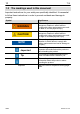
Table Of Contents
- T12
- Contents
- Safety instructions
- 1 Markings used
- 2 Scope of supply
- 3 Operation
- 4 Application
- 5 Signal flow
- 6 Structure and mode of operation
- 7 Mechanical installation
- 7.1 Important precautions during installation
- 7.2 Conditions on site
- 7.3 Mounting position
- 7.4 Installing the slotted disc (rotational speed measuring system only)
- 7.5 Installing the rotor
- 7.6 Fitting the protection against contact (option)
- 7.7 Installing the stator
- 7.8 Optical rotational speed/angle of rotation measuring system (option)
- 8 LED status display
- 9 Electrical connection
- 10 Shunt signal
- 11 Load‐carrying capacity
- 12 TEDS
- 13 Maintenance
- 14 Waste disposal and environmental protection
- 15 Specifications
- 16 Dimensions
- 16.1 Rotor 100 N⋅m to 200 N⋅m
- 16.2 Rotor 500 N⋅m to 10 kN⋅m
- 16.3 Stator 100 N⋅m to 200 N⋅m with rot.speed meas. system
- 16.4 Stator 100 N⋅m to 200 N⋅m with rot. speed meas. system
- 16.5 Stator 100 N⋅m to 10 kN⋅m with rot. speed meas. system
- 16.6 Stator 100 N⋅m to 200 N⋅m with prot. against contact
- 16.7 Stator 100 N⋅m to 200 N⋅m with prot. against contact
- 16.8 Stator 500 N⋅m to 1 kN⋅m with prot. against contact
- 16.9 Stator 2 kN⋅m to 10 kN⋅m with prot. against contact
- 16.10 Mounting dimensions
- 17 Supplementary technical information
- 18 Condition at the time of delivery
- 19 Ordering numbers
- 20 Accessories

3
T12
A1979−10.0 en HBM
Contents Page
Contents
Safety instructions 5..............................................
1 Markings used 9...............................................
1.1 Symbols on the transducer and / or Stator 9...................
1.2 The markings used in this document 10........................
2 Scope of supply 11.............................................
3 Operation 11...................................................
4 Application 12..................................................
5 Signal flow 13..................................................
6 Structure and mode of operation 14..............................
7 Mechanical installation 16.......................................
7.1 Important precautions during installation 16....................
7.2 Conditions on site 17........................................
7.3 Mounting position 17........................................
7.4 Installing the slotted disc (rotational speed measuring system
only) 18...................................................
7.5 Installing the rotor 19........................................
7.6 Fitting the protection against contact (option) 21................
7.7 Installing the stator 27.......................................
7.7.1 Preparing with the mounting kit (included among the items
supplied) 28..........................................
7.7.2 Aligning the stator 30..................................
7.7.3 Stator installation over the protection against contact
(option) 32...........................................
7.8 Optical rotational speed/angle of rotation measuring system
(option) 33.................................................
7.8.1 Axial alignment 33....................................
7.8.2 Radial alignment 34...................................
8 LED status display 36...........................................
8.1 Measuring mode operation 36................................
8.2 Rotor clearance setting mode operation 36.....................
8.3 Rotational speed measuring system setting mode operation 36...
9 Electrical connection 37.........................................
9.1 General information 37......................................
9.2 Shielding design 39.........................................