Mounting Instructions | Montageanleitung English T40FM Deutsch
Hottinger Baldwin Messtechnik GmbH Im Tiefen See 45 D-64239 Darmstadt Tel. +49 6151 803-0 Fax +49 6151 803-9100 Email: info@hbm.com Internet: www.hbm.com Mat.: 7-2001.3276 DVS: A3276-8.0 HBM: public 02.2015 E Hottinger Baldwin Messtechnik GmbH. Subject to modifications. All product descriptions are for general information only. They are not to be understood as a guarantee of quality or durability. Änderungen vorbehalten. Alle Angaben beschreiben unsere Produkte in allgemeiner Form.
Mounting Instructions | Montageanleitung English T40FM Deutsch
English 1 Safety information . . . . . . . . . . . . . . . . . . . . . . . . . . . . . . . . . . . . . . . . 4 2 2.1 2.2 Markings used . . . . . . . . . . . . . . . . . . . . . . . . . . . . . . . . . . . . . . . . . . . . Symbols on the transducer . . . . . . . . . . . . . . . . . . . . . . . . . . . . . . . . . . The marking used in this document . . . . . . . . . . . . . . . . . . . . . . . . . . . 11 11 12 3 Applications . . . . . . . . . . . . . . . . . . . . . . . . . . . . . . . . . . . . . .
7 Shunt signal . . . . . . . . . . . . . . . . . . . . . . . . . . . . . . . . . . . . . . . . . . . . . . 52 8 8.1 8.2 Functionality testing . . . . . . . . . . . . . . . . . . . . . . . . . . . . . . . . . . . . . . Rotor status, LED A (upper LED) . . . . . . . . . . . . . . . . . . . . . . . . . . . . . Stator status, LED B (lower LED) . . . . . . . . . . . . . . . . . . . . . . . . . . . . 53 54 55 9 Loading capacity . . . . . . . . . . . . . . . . . . . . . . . . . . . . . . . . . . . . . . . .
Safety information 1 Safety information FCC Compliance & Advisory Statement Important Any changes or modification not expressly approved in writing by by the party responsible for compliance could void the user’s authority to operate the device. Where specified additional components or accessories else where defined to be used with the installation of the product, they must be used in order to ensure compliance with FCC regulations. This device complies with Part 15 of the FCC Rules.
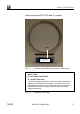
Safety information Label example with FCC ID and IC number. Label Model: T40S7 FCC ID: 2ADAT-T40S7TOS9 IC: 12438AT40S7TOS9 This device complies with part 15 of the FCC Rules. Opera tion is subject to the following two conditions: (1) This device may not cause harmful interference, and (2) this device must accept any interference received, including interference that may cause undesired operation. Fig. 1.
Safety information This device complies with Industry Canada standard RSS210. This device complies with Industry Canada license−exempt RSS standard(s).Operation is subject to the following two conditions: (1) this device may not cause interference, and (2) this device must accept any interference, including interference that may cause unde sired operation of the device. Cet appareil est conforme aux norme RSS210 d’Industrie Canada.
Safety information proper transportation, correct storage, siting and mount ing, and careful operation. Load carrying capacity limits The data in the technical data sheets must be complied with when using the torque flange. The respective spe cified maximum loads in particular must never be ex ceeded. For example, the values stated in the specifica tions must not be exceeded, e.g.
Safety information S The covering agent or cladding should prevent squeezing or shearing and provide protection against parts that might come loose. S Covering agents and cladding must be positioned at a suitable distance or be so arranged that there is no access to any moving parts within. S Covering agents and cladding must still be attached even if the moving parts of the torque flange are in stalled outside people's movement and working range.
Safety information ted, installed and operated by untrained personnel. Every person involved with siting, starting-up, operating or re pairing a torque flange must have read and understood the mounting instructions and in particular the technical safety instructions.
Safety information Qualified Personnel Qualified personnel means persons entrusted with siting, mounting, starting up and operating the product, who possess the appropriate qualifications for their function. This includes people who meet at least one of the three following requirements: 1. Knowledge of the safety concepts of automation tech nology is a requirement and as project personnel, you must be familiar with these concepts. 2.
Markings used 2 Markings used 2.1 Symbols on the transducer Read and note the data in this manual CE mark The CE mark enables the manufacturer to guarantee that the product complies with the requirements of the relev ant EC directives (the Declaration of Conformity can be found on the HBM website at www.hbm.com under HBM doc). Model: T40S7 FCC ID: 2ADAT-T40S7TOS9 IC: 12438AT40S7TOS9 This device complies with part 15 of the FCC Rules.
Markings used 2.2 The marking used in this document Important instructions for your safety are specifically iden tified. It is essential to follow these instructions in order to prevent accidents and damage to property. Symbol Significance WARNING This marking warns of a potentially dangerous situ ation in which failure to comply with safety require ments can result in death or serious physical injury.
Applications 3 Applications The T40FM torque flange measures static and dynamic torques on stationary and rotating shafts. Test beds can be extremely compact because of the compact design of the transducer. This offers a very wide range of applica tions. The T40B torque flange is reliably protected against elec tromagnetic interference. It has been tested according to harmonized European standards and/or complies with US and Canadian standards. The product carries the CE mark and/or FCC label.
Structure and Mode of Operation 4 Structure and Mode of Operation The torque flange consists of two separate parts: the ro tor and the stator. The rotor comprises the measuring body and the signal transmission elements. Strain gauges (SGs) are installed on the measuring body. The rotor electronics for transmitting the bridge excitation voltage and the measurement signal are located centrally in the flange.
Structure and Mode of Operation Antenna segments Rotor Connector plugs Connector plugs Identification plate Fig. 4.1 Stator housing Mechanical construction without a rotational speed measuring system, Option 7, Code S The rotational speed sensor is mounted on the stator in Option 6 with a rotational speed measuring system. The customer mounts the rotational speed disc between the measuring body and customer flange. The rotational speed is measured magnetically with an AMR sensor and magnetic tape.
Structure and Mode of Operation Antenna segments Rotational speed disc Sensor head for measuring rotational speed Rotor Connector plugs Connector plugs Identification plate Fig. 4.2 16 Stator housing Mechanical construction with a speed measuring system, Option 7, Code S A3276-8.
Structure and Mode of Operation Antenna segments with mounted shielding plates Stator housing Connector plugs Fig. 4.3 Mechanical construction of Stator with mounted shielding plates without rotational speed, FCC option Fig. 4.4 Individual shielding plates, FCC option Dismounted shielding plates Axial shielding plates Radial shielding plate T40FM A3276-8.
Structure and Mode of Operation Important The use of the shielding plates are important to ensure compliance with FCC regulations. If the shielding plates has to be removed for any purpose (e.g. installation or maintenance), they must be replaced in the original posi tion before the product is used. 18 A3276-8.
Mechanical installation 5 Mechanical installation 5.1 Important precautions during installation Notice A torque flange is a precision measuring element and therefore needs careful handling. Dropping or knocking the transducer may cause permanent damage. Make sure that the transducer cannot be overloaded, including while it is being mounted. S Handle the transducer with care.
Mechanical installation prestressing loss due to screw slackening, in the event of alternating loads. S Comply with the mounting dimensions to enable cor rect operation. An appropriate shaft flange enables the T40FM torque flange to be mounted directly. It is also possible to mount a joint shaft or relevant compensating element directly on the rotor (using an intermediate flange when required).
Mechanical installation and the flange, the values given in the specifications can be exceeded. In this case, ensure static temperature ra tios by cooling or heating, depending on the application. As an alternative, check if thermal decoupling is possible, e.g. by means of heat radiating elements such as multiple disc couplings. 5.3 Installation orientation The torque flange can be installed with any orientation.
Mechanical installation 5.4.1 Installation without dismantling the antenna ring, FCC option with antenna shielding cover Mounting supplied by customer 1. Install rotor 2. Install stator Support supplied by customer 3. Finish shaft train installation 22 A3276-8.0 HBM: public 4.
Mechanical installation 5.4.2 Installation with subsequent stator mounting, Option 7, Code S 2. Install shaft train 1. Install rotor Washers 3. Dismantle antenna segment 4. Install antenna segment Support supplied by customer Fan-type lock washers 4. Fit support T40FM A3276-8.
Mechanical installation 5.5 Preparing for the rotor mounting CAUTION The rotor is very heavy (depending on measuring range: 18kg … 39kg)! Use a crane or other suitable lifting equipment to lift it out of its packaging and install it. Two eye bolts are screwed into the rotor as transport and mounting aids. Hook the lifting equipment to these eye bolts as this ensures that the rotor is lifted horizontally out of the packaging (see Fig. 5.1). Transport and mounting eye bolts Fig. 5.
Mechanical installation 1. Lift the rotor out of the packaging, rotate horizontally by 180_, so that flange B is pointing upwards (see Fig. 5.1). Flange B Fig. 5.2 Rotating the rotor 2. Place the rotor carefully onto a clean and stable table. 3. If the rotor is to be installed horizontally as shown in Fig. 5.3, remove one mounting eye bolt. Both mount ing eye bolts can initially remain in the flange for ver tical installation. T40FM A3276-8.
Mechanical installation Fig. 5.3 Rotor installation (horizontal) 4. Clean the plane faces of the transducer flange and the counter flange. For safe torque transfer, the faces must be clean and free from grease. Use a piece of cloth or paper soaked in solvent. Make sure that no solvent drips into the inside of the transducer and that the transmitter coils are not damaged during cleaning. 5. Fasten the lifting equipment to the mounting eye bolt(s). 6.
Mechanical installation 5.6 Mounting the rotor Tip Usually the rotor type plate is no longer visible after in stallation. This is why we include with the rotor additional stickers with the important characteristics, which you can attach to the stator or any other relevant test-bench com ponents. You can then refer to them whenever there is anything you wish to know, such as the shunt signal.
Mechanical installation Hexagon socket screw (Z) DIN EN ISO 4762 (10.9) Measuring zone Fastening bolt (10.9); note maximum thread reach Y! Flange A Fig. 5.4 Bolted rotor connection 2. For the connection of flange A (see Fig. 5.4), use DIN EN ISO 4762 property class 10.9 hexagon socket screws of a suitable length (dependent on the connection geometry, see Tab. 5.1 on Page 30).
Mechanical installation Important Keep them in a safe place for future dismounting. 5. There are relevant tapped holes on flange B for con tinuing the shaft train mounting. Again use screws of property class 10.9 and tighten them with the pre scribed torque, as specified in Tab. 5.1, Page 30. Important Use a threadlocker (medium strength, e.g. LOCTITE) to glue the screws into the counter thread to exclude prestressing loss due to screw slackening, in the event of alternating loads.
Mechanical installation Measuring range kNVm Fastening screws Z1) Maximum thread reach Y of screws in flange B Prescribed tightening moment mm NVm 30 400 40 560 45 760 Property class 15 20 M18 25 30 40 10.9 M20 50 60 70 M22 80 1) DIN EN ISO 4762; black/oiled/mtot=0.125 Tab. 5.1 Fastening screws Important Dry screw connections can result in different and higher friction factors (see VDI 2230, for example). This means a change to the required tightening moments.
Mechanical installation 5.7 Installing the stator On delivery, the stator has already been installed and is ready for operation. The upper antenna segment can be separated from the stator, for example, for maintenance or to facilitate stator mounting, only for Option 7, Code S. If your application does not require the stator to be dis mantled, proceed as described in points 2., 5., and 6 for Option 7, Code S.
Mechanical installation Antenna segments with mounted shielding plates Stator housing Connector plugs Fig. 5.6 Mechanical construction of Stator with mounted shielding plates without rotational speed, FCC option Fig. 5.7 Individual shielding plates, FCC option Dismounted shielding plates Axial shielding plates Radial shielding plate 32 A3276-8.
Mechanical installation Important The use of the shielding plates are important to ensure compliance with FCC regulations. If the shielding plates has to be removed for any purpose (e.g. installation or maintenance), they must be replaced in the original posi tion before the product is used. Important If the shielding plates has to be removed for installation or maintenance, tighten the screws to fix the shielding plates with a tightening torque of 1.6 Nm.
Mechanical installation opportunity for horizontal and vertical adjustments. Do not fully tighten the bolts yet. 3. Now use two hexagon socket screws to mount the upper antenna segment removed in Point 1 on the lower antenna segment. Make sure that the two fan-type lock washers are in serted between the antenna segments (these ensure that there is a defined contact resistance)! Important To make sure that they function perfectly, the fan-type lock washers (A5.
Mechanical installation Fig. 5.9 Alignment of the rotor with the stator, Option 7, Code S and FCC option 6. Now fully tighten the bolted stator housing connection. Prevention of axial stator oscillation Depending on the operating conditions, the stator may be induced to oscillate. This effect is dependent on: T40FM S the rotational speed, S the antenna diameter (depends in turn on the measur ing range), S the design of the machine base. A3276-8.
Mechanical installation Important To prevent this axial oscillation, the antenna ring requires additional support by the customer. There is a socket (with an M5 internal thread) on the upper antenna seg ment, which can be used for a suitable clamping device (see Fig. 5.10). If this is the case, the cable plug also needs some sup port, as shown in the construction example in Fig. 5.11. Fig. 5.10 36 Construction example for supporting the antenna ring, Option 7, Code S and FCC option A3276-8.
Mechanical installation Fig. 5.11 T40FM Construction example for connector terminals (for two plugs), Option 7, Code S and FCC option A3276-8.
Mechanical installation 5.8 Mounting the rotational speed flange (rotational speed measuring system only) The rotational speed disc (intermediate flange) is readymounted on the rotor at the factory, with two (M4) screws. Rotational speed disc M4 fixing screws Sensor head for measuring rotational speed Sensor head for reference signal Fig. 5.
Mechanical installation Important The speed measuring system uses a magnetic measur ing principle. In applications where high magnetic field strengths can occur, e.g. eddy-current brakes, implement suitable measures to ensure that the maximum permiss ibly magnetic field strength cannot be exceeded (see Chapter 14 "Specifications", Page 78).
Mechanical installation Do not adjust Sensor head screws Fig. 5.13 40 Torque transducer with speed disc and sensor head, and reference signal (optional), Option 7, Code S and FCC option A3276-8.
Electrical Connection 6 Electrical Connection 6.1 General information S With extension cables, make sure that there is a proper connection with minimum contact resistance and good insulation. S All cable connectors or swivel nuts must be fully tightened. Important Transducer connection cables from HBM with plugs at tached are identified in accordance with their intended purpose (Md or n).
Electrical Connection Special electronic coding methods are used to protect the purely digital signal transmission between the transmitter head and the rotor from electromagnetic interference. The cable shield is connected with the transducer hous ing. This encloses the measurement system (without the rotor) in a Faraday cage when the shield is laid flat at both ends of the cable.
Electrical Connection S Should differences in potential between the machine rotor and stator, because of unchecked leakage, for example, cause interference, this can usually be over come by connecting the rotor definitively to ground, e.g. with a wire loop. The stator must be connected to the same (ground) potential. 6.3 Pin Assignment The stator housing has two 7-pin plugs, an 8-pin plug and a 16-pin plug.
Electrical Connection Assignment for plug 1 - Supply voltage and frequency output signal 6 1 Device plug 5 7 2 Top view 3 4 KAB153 KAB149 KAB1781) Plug Assignment pin Color code D‐SUB‐ plug pin HD‐SUB‐ plug pin 1 Torque measurement signal (frequency output; 5 V2,3) wh 13 5 2 Supply voltage 0 V; bk 5 - 3 Supply voltage 18 V to 30 V bu 6 - 4 Torque measurement signal (frequency output; 5 V2,3) rd 12 10 5 Measurement signal 0 V; symmetrical gy 8 6 6 Shunt signal trigger
Electrical Connection Notice Torque flanges are only intended for operation with a DC supply voltage. They must not be connected to older HBM amplifiers with square-wave excitation. This could destroy the connection board resistors or cause other faults in the amplifiers. T40FM A3276-8.
Electrical Connection Assignment for plug 2 - Rotational speed measurement system 2 5 4 3 8 7 Plug pin 1 Device plug Top view 6 Assignment KAB154 KAB150 KAB1791) Color code D-SUBplug pin HD-SUBplug pin 1 Rotational speed measurement signal2) (pulse string, 5 V; 0°) rd 12 10 2 Not in use bl - - 3 Rotational speed measurement signal2) (pulse string, 5 V; 90° phase shifted) gy 15 8 4 Not in use bl - - 5 Not in use vi - - 6 Rotational speed measurement signal2) (pulse s
Electrical Connection Assignment for plug 2 - Rotational speed measurement system with reference signal 2 5 4 3 8 7 Plug pin 1 Device plug Top view 6 KAB164 KAB163 KAB1811) Color code D-SUBplug pin HD-SUBplug pin Assignment 1 Rotational speed measurement signal 2) (pulse string, 5 V) rd 12 10 2 Reference signal (1 pulse/revolution, 5 V) 2) bl 2 3 gy 15 8 2) 3 Rotational speed measurement signal (pulse string, 5 V; 90° phase shifted) 4 Reference signal (1 pulse/revolution, 5
Electrical Connection Pin 1 Pin 6 Pin 3 Pin 7 Pin 2 Pin 4 Fig. 6.1 48 Rotational speed signals at plug 2 (rotational speed in the direction of the arrow) A3276-8.
Electrical Connection Pin 1 Pin 6 Pin 3 Pin 7 Pin 2 Pin 4 Fig. 6.2 T40FM Rotational speed signals at plug 2 (rotational speed against the direction of the arrow) A3276-8.
Electrical Connection Assignment for plug 3 - Supply voltage and voltage output signal Plug pin Device plug 6 5 1 7 4 2 1 Torque measurement signal (voltage output; 0 V) 2 Supply voltage 0 V; 3 Supply voltage 18 V to 30 V DC 4 Torque measurement signal (voltage output; ±10 V) 5 Not in use 6 Shunt signal trigger 5 V to 30 V 7 Shunt signal 0 V; 3 Top view Assignment Shielding connected to housing ground Assignment for plug 4 TMC - only for connection to the TIM 40 Torque Interface Modu
Electrical Connection The information in this Chapter relates to the self-con tained operation of the T40FM without HBM system solu tions. The supply voltage is electrically isolated from signal out puts and shunt signal inputs. Connect a separated extralow voltage of 18 V … 30 V to pin 3 (+) and pin 2 ( ) of plugs 1 or 3. We recommend that you use HBM cable KAB 8/00-2/2/2 and the appropriate sockets (see Ac cessories).
Shunt signal 7 Shunt signal The T40FM torque flange delivers an electrical shunt sig nal that can be activated from the amplifier for measuring chains with HBM components. The transducer generates a shunt signal of about 50% of the nominal (rated) torque; the precise value is specified on the type plate. After ac tivation, adjust the amplifier output signal to the shunt signal supplied by the connected transducer, to adapt the amplifier to the transducer.
Functionality testing 8 Functionality testing You can check the functionality of the rotor and the stator from the LEDs on the stator. LED A, rotor status LED B, stator status Fig. 8.1 LEDs on the stator housing, Option 7, Code S and FCC option Important Once the supply voltage is applied, the torque transducer needs up to a further 4 seconds to be ready for operation. T40FM A3276-8.
Functionality testing 8.1 Rotor status, LED A (upper LED) Color Significance Green (pulsating) Internal rotor voltage values ok Flashing orange Rotor and stator mismatched (an increasing flashing frequency indicates the degree of misalignment) => Correct the rotor/stator alignment Pulsating orange Rotor status cannot be defined => Correct the rotor/stator alignment If the LED still pulsates orange, it is possible that there is a hardware defect.
Functionality testing 8.2 Stator status, LED B (lower LED) Color Significance Green (permanently lit) Measurement signal transmission and internal stator voltages ok Green, intermittently orange. Orange until end of defective transmission if y5 incorrect measured values are transmitted in succession. The measurement signals reflect the level of the defect status for the duration of the transmission defect + for approx. another 3.3ms.
Loading capacity 9 Loading capacity Nominal torque can be exceeded statically up to the limit torque. If the nominal torque is exceeded, additional ir regular loading is not permissible. This includes longitud inal forces, lateral forces and bending moments. Limit values can be found in Chapter 14 "Specifications" on Page 78. Measuring dynamic torque The torque flange can be used to measure static and dy namic torque.
Loading capacity Nominal (rated) torque Mnom as a% + Mnom Vibration bandwidth Vibration bandwidth 0 Time t 200% oscillation width Vibration bandwidth - Mnom Fig. 9.1 T40FM Permissible dynamic loading A3276-8.
Maintenance 10 Maintenance The T40FM torque flanges are maintenance-free. 58 A3276-8.
Waste disposal and environmental protection 11 Waste disposal and environmental protection All electrical and electronic products must be disposed of as hazardous waste. The correct disposal of old equip ment prevents ecological damage and health hazards. Statutory waste disposal mark The electrical and electronic devices that bear this sym bol are subject to the European waste electrical and elec tronic equipment directive 2002/96/EC.
Dimensions 12 Dimensions 12.1 T40FM without speed measurement, Option 7, Code S 12.1.1 T40FM 15 kNm - 25 kNm 17 44 10 22 61.5 11.25° A M18 22.5° 16 x 22.5° = 360° 226.5 Ø 206 Ø 250.5 Mounting dimensions 9 190 Dimensions in mm (1 mm = 0.03937 inches) 12 16 27 53 53 27 12 A 152 210 55.5 34 45 35 Ø 16 11.1 M5 for axial locking 60 A3276-8.
Dimensions T40FM 15kNm - 25kNm, continued Dimensions in mm (1 mm = 0.03937 inches) Center of gravity 16x22.55 = 360° Ø19+0.2 Ø288 Ø326 3 375 Ø174H6 5.2 Ø174g5 31.4 22.5° Ø16 15 Alignment plane rotor - stator 73 25 32 1.5 16 Cutaways in Section A-A T40FM A3276-8.
Dimensions 12.1.2 T40FM 30 kNm - 50 kNm 17 9 44 190 10 67 22 Mounting dimensions Dimensions in mm (1 mm = 0.03937 inches) 15° 24x15° = 360° M20 248 11.1 12 27 53 12 53 27 35 45 Ø16 Ø250 Ø293.5 A 16 A 152 210 64.25 34 35.2 18.5 M5 for axial locking Alignment plane 85 rotor - stator 25 38.5 1.5 5.2 15° 24x15° = 360° 4 Ø350 Ø390 Ø16 Center of gravity 2 Ø210g5 418 Ø210H6 Ø21.0+0. 16 Cutaways in section A-A 62 A3276-8.
Dimensions 12.1.3 T40FM 60 kNm - 80 kNm 44 10 22 71.5 Mounting dimensions 9 17 190 Dimensions in mm (1 mm = 0.03937 inches) 12 53 27 27 53 11.1 12 152 210 34 71.5 16 35 45 ∅ 16 263 ∅275 ∅323.5 15° M22 24x15° = 360° Center of gravity ∅385 4 ∅425 ∅240H6 5.2 ∅240g5 448 21.5 ∅ 16 40.6 M5for axial locking Alignment plane 15° 24x15° = 360° rotor - stator 95 +0.2 ∅23 30 44 1.5 16 Cutaways in section A−A T40FM A3276-8.
Dimensions 12.2 T40FM with speed measurement, Option 7, Code S 12.2.1 T40FM 15 kNm - 25 kNm Dimensions in mm (1 mm = 0.03937 inches) 10 17 22 A 22.5° 16x22.5° = 360° B ∅250.5 Mounting dimensions 61.5 11.25° M18 44 9 190 226.5 ∅206 B 11.1 12 53 27 35 45 ∅16 53 27 ∅16 16 A 152 210 55.5 34 M5 for axial locking 64 A3276-8.
Dimensions T40FM 15kNm - 25kNm, continued Dimensions in mm (1 mm = 0.03937 inches) 87.5 73 33 25 37.8 32 5.2 16x22.5° = 360° 22.5° Alignment plane rotor - stator ∅19+0.2 1.5 ∅288 ∅326 ∅250 375 99.9 1.6 ∅174 H6 (174.025) 174.000 ∅174 g5( 173.986 173.968) 4 ∅16 ∅16 16 8 Center of gravity Cutaways in section A-A 14.5 ∅19 Rotational speed flange B–B T40FM A3276-8.
Dimensions 12.2.2 T40FM 30 kNm - 50 kNm 9 15° 24x15° = 360° M20 248 Ø250 Ø293.5 A 44 10 17 190 67 22 Mounting dimensions Dimensions in mm (1 mm = 0.03937 inches) 11.1 16 27 A 152 210 64.25 34 53 27 35 45 Ø16 53 12 Ø16 M5 for axial locking 66 A3276-8.
Dimensions T40FM 30kNm - 50kNm, continued Dimensions in mm (1 mm = 0.03937 inches) 38.5 5.2 15° 24x15° = 360° ∅21.5+0.2 1.5 ∅350 ∅390 ∅293 ∅16 ∅16 16 99.9 1.6 210.029 ∅210 H6 ( 210.000) 209.985) ∅210 g5 (209.965 4 418 40.9 Alignment plane rotor - stator 99.5 85 41.5 25 14.5 Center of gravity 14.5 Cutaways in section A-A ∅21 Rotational speed flange A–A T40FM A3276-8.
Dimensions 12.2.3 T40FM 60 kNm - 80 kNm Dimensions in mm (1 mm = 0.03937 inches) 9 44 10 22 71.5 Mounting dimensions 17 190 15° 24x15° = 360° M22 263 Ø275 Ø323.5 A 11.1 16 27 53 A 152 210 71.5 34 12 53 27 35 45 Ø16 Ø16 M5 for axial locking 68 A3276-8.
Dimensions T40FM 60kNm - 80kNm, continued Dimensions in mm (1 mm = 0.03937 inches) Alignment plane rotor - stator 109.5 95 43.5 30 15° +0.2 Ø 23 24x15° = 360° 45.7 44 1.5 Ø385 Ø425 Ø323 239.985) Ø240 g5 (239.965 Ø16 Ø16 16 99.9 1.6 240.029) Ø240 H6 (240.000 448 4 5.2 20 Center of gravity 14.5 Cutaways in section A-A Ø 23 Rotational speed flange A–A T40FM A3276-8.
Dimensions 12.3 T40FM with rotational speed measurement and reference signal, Option 7, Code S 12.3.1 T40FM 15 kNm - 25 kNm 9 190 44 22 10 61.5 11.25° A 22.5° M18 16 x 22.5° = 360° B ∅250.5 Mounting dimensions 17 Dimensions in mm (1 mm = 0.03937 inches) 226.5 ∅206 B 53 27 A 152 210 55.5 34 12 53 27 35 16 45 11.1 ∅16 ∅16 M5 for axial locking 70 A3276-8.
Dimensions T40FM 15kNm - 25kNm, continued Dimensions in mm (1 mm = 0.03937 inches) 87.5 73 25 32 1.5 16 x 22.5° = 360° 22.5° ∅19 +0.2 8 ∅16 ∅16 Center of gravity 16 ∅288 ∅326 99.9 2 375 4 ) ∅174 H6 (174.025 174.000 5.2 7.3 ∅174 g5 (173.986 ) 173.968 1.6 ∅250 15 37.8 Alignment plane rotor - stator (14.5) 8 Cutaways in section A-A (14.5) ∅19 Rotational speed flange – B B T40FM A3276-8.
Dimensions 12.3.2 T40FM 30 kNm - 50 kNm Dimensions in mm (1 mm = 0.03937 inches) 9 44 10 22 Mounting dimensions 67 17 190 15° A 24 x15° = 360° 248 ∅250 ∅293.5 M20 27 A 152 210 64.25 34 53 12 27 35 45 16 53 11.1 ∅16 ∅16 M5 for axial locking 72 A3276-8.
Dimensions T40FM 30kNm - 50kNm, continued Dimensions in mm (1 mm = 0.03937 inches) Alignment plane rotor - stator 99.5 85 18.5 40.9 25 38.5 5.2 24 x15° = 360° 1.5 ∅16 ∅16 16 ∅350 ∅390 418 99.9 7.3 1.6 8 ∅293 ∅210 g5 ( 209.985 ) 209.965 ∅210 H6 ( 210.029) 210.000 4 2 Center of gravity 15° ∅21+0.2 (14.5) 14.5 Cutaways in section A-A (14.5) ∅21 Rotational speed flange – A A T40FM A3276-8.
Dimensions 12.3.3 T40FM 60 kNm - 80 kNm 9 Dimensions in mm (1 mm = 0.03937 inches) 44 10 22 Mounting dimensions 71.5 17 190 15° 24 x15° = 360° M22 263 ∅275 ∅323.5 A 11.1 16 27 A 152 210 71.5 34 53 12 53 27 35 45 ∅16 ∅16 M5 for axial locking 74 A3276-8.
Dimensions T40FM 60kNm - 80kNm, continued Dimensions in mm (1 mm = 0.03937 inches) 109.5 95 21.5 Alignment plane rotor - stator 30 (14.5) 44 1.5 15° 24 x15° = 360° ∅23 +0.2 45.7 ∅16 ∅16 Center of gravity 16 ∅385 ∅425 ∅323 1.6 99.9 239.985 ) 239.965 ∅240 g5 ( 8 7.3 2 448 4 ∅240 H6 ( 240.029 ) 240.000 5.2 20 (14.5) Cutaways in section A-A ∅23 Rotational speed flange – A A T40FM A3276-8.
Order numbers, Accessories 13 76 Order numbers, Accessories A3276-8.
Order numbers, Accessories Accessories, to be ordered separately Article Order no.
Order numbers, Accessories 14 Specifications Type T40FM Accuracy class 0.1 Nominal (rated) torque Mnom kNVm Nominal (rated) rotational speed Optional 15 20 25 30 40 50 60 70 80 rpm 6000 4000 3000 rpm 8000 6000 4500 Torque measuring system, frequency output Nominal (rated) sensitivity (nom inal (rated) signal range between torque = zero and nominal (rated) torque) Option SU2 kHz 5 Option DU2 kHz 30 Option HU2 kHz 120 % " 0.2 Between 0% v. Mnom and 20% v. Mnom % <"0.
Order numbers, Accessories Nominal (rated) torque Mnom kNVm 15 20 25 30 40 50 60 70 80 Output signal at zero torque Option SU2 kHz 10 Option DU2 kHz 60 Option HU2 kHz 240 At positive nominal (rated) torque, Option SU2 kHz 15 At positive nominal (rated) torque, Option DU2 kHz 90 At positive nominal (rated) torque, Option HU2 kHz 360 At negative nominal (rated) torque, Option SU2 kHz 5 At negative nominal (rated) torque, Option DU2 kHz 30 At negative nominal (rated) torque, Optio
Order numbers, Accessories Nominal (rated) torque Mnom kNVm 15 20 25 30 40 50 60 70 80 Temperature effect per 10 K in the nominal (rated) temperature range on the output signal, related to the actual value of the signal span % <"0.1 on the zero signal, related to the nominal (rated) sensitivity % <"0.05 Long-term drift over 48 h at refer ence temperature, related to the nominal (rated) sensitivity % ≤0.
Order numbers, Accessories Nominal (rated) torque Mnom kNVm 15 20 25 30 40 50 60 70 80 At positive nominal (rated) torque kHz 10 At negative nominal (rated) torque kHz -10 Maximum modulation range 2 V "12 invalid measured value V 13 ... 15 kΩ >10 mV <40 (peak-to-peak) on the output signal, related to the actual value of the signal span % ≤0.2 on the zero signal, relative to the nominal (rated) sensitivity % <"0.15 % <"0.
Order numbers, Accessories Nominal (rated) torque Mnom kNVm 15 20 25 30 40 50 4) degrees < "0.05 Maximum permissible output fre quency kHz 420 Group delay μs < 150 Radial nominal (rated) distance between sensor head and mag netic ring (mechanical distance) mm 1.6 Working distance range between sensor head and magnetic ring 5) mm 0.4 … 2.5 Max. permissible axial displace ment of the rotor to the stator 6) mm "1.5 Torsional vibration of the rotor degrees < approx. 0.
Order numbers, Accessories Nominal (rated) torque Mnom kNVm Relative humidity / no condens ation 15 20 25 30 % 40 50 60 70 80 5 ... 95 Reference signal measuring system (zero index) Measurement system Magnetic, with Hall sensor and magnet Output signal V 5 V symmetrical (RS 422) Pulses per revolution 1 Minimum rotational speed for sufficient pulse stability rpm 2 degrees 0.088 degrees <"0.
Order numbers, Accessories Nominal (rated) torque Mnom kNVm 15 20 25 30 Protection class, as per EN 60529 (rotor/stator) 40 50 60 70 80 IP 54 Shunt Nominal (rated) trigger voltage V 5 Trigger voltage limit V 36 Calibration signal on Vmin >2.5 Calibration signal off Vmin <0.7 % <"0.05 VDC 18 ... 30 In measuring mode A <1 (typ. 0.3 at 20 V supply voltage) In startup mode A <4 (typ. 2) for max. 50μs Nominal (rated) power consump tion W <10 (typ.
Order numbers, Accessories Nominal (rated) torque Mnom kNVm 15 20 25 30 40 50 Contact discharge kV 4 Air discharge kV 8 Fast transients (burst) kV 1 Impulse voltages (surge) kV 1 Conducted interference V 10 Quantity n 1000 Duration ms 3 m/s2 650 Hz 10 ... 2000 h 2.
Order numbers, Accessories Nominal (rated) torque Mnom kNVm Additional maximum plumb/par allel deviation at limit bending moment 15 20 25 30 mm 40 50 <0.5 Balance quality level, as per DIN ISO 1940 60 70 80 <0.7 G 6.3 Mechanical data Permissible max.
Order numbers, Accessories Nominal (rated) torque Mnom kNVm Permissible axial displacement between rotor and stator (without ro tational speed measuring system) 18) 15 20 25 30 40 50 60 70 80 "2 mm Weight Rotor without speed measuring system kg 18 28 39 Rotor with rotational speed measuring system kg 20 32 42 Stator kg 1.8 2.1 3.0 1) 2) 3) 4) 5) 6) 7) 8) Output signal range in which there is a repeatable correlation between torque and output signal.
Supplementary Technical Information 15 Supplementary Technical Information Axial and radial run-out tolerances 0.02 AB 0.02 AB A 0.02 AB Internal centering Flange B Flange A Hardness 47 ±2 HRC 0.
Mounting Instructions | Montageanleitung English T40FM Deutsch
Deutsch 1 Sicherheitshinweise . . . . . . . . . . . . . . . . . . . . . . . . . . . . . . . . . . . . . . 4 2 2.1 2.2 Verwendete Kennzeichnungen . . . . . . . . . . . . . . . . . . . . . . . . . . . . . Auf dem Aufnehmer angebrachte Symbole . . . . . . . . . . . . . . . . . . . . In dieser Anleitung verwendete Kennzeichnungen . . . . . . . . . . . . . . 12 12 13 3 Anwendung . . . . . . . . . . . . . . . . . . . . . . . . . . . . . . . . . . . . . . . . . . . . . . 14 4 Aufbau und Wirkungsweise .
8.2 Statorstatus, LED B (untere LED) . . . . . . . . . . . . . . . . . . . . . . . . . . . . 55 9 Belastbarkeit . . . . . . . . . . . . . . . . . . . . . . . . . . . . . . . . . . . . . . . . . . . . . 57 10 Wartung . . . . . . . . . . . . . . . . . . . . . . . . . . . . . . . . . . . . . . . . . . . . . . . . . . 59 11 Entsorgung und Umweltschutz . . . . . . . . . . . . . . . . . . . . . . . . . . . . 60 12 12.1 12.1.1 12.1.2 12.1.3 12.2 12.2.1 12.2.2 12.2.3 12.3 Abmessungen . . . . . . . . .
Sicherheitshinweise 1 Sicherheitshinweise FCC-Konformität und Hinweis Wichtig Durch Änderungen, die nicht ausdrücklich schriftlich von der für die Konformität zuständigen Person genehmigt wurden, könnte die Berechtigung zum Betrieb des Geräts verfallen. Sofern angegeben, müssen zusätzliche Komponenten oder Zubehörteile, deren Verwendung bei der Installation des Produkts an anderer Stelle vorgege ben ist, verwendet werden, um die Einhaltung der FCCVorschriften zu gewährleisten.
Sicherheitshinweise Beispiel eines Schildes mit FCC-ID und IC-Nummer. Schild Model: T40S7 FCC ID: 2ADAT-T40S7TOS9 IC: 12438AT40S7TOS9 This device complies with part 15 of the FCC Rules. Opera tion is subject to the following two conditions: (1) This device may not cause harmful interference, and (2) this device must accept any interference received, including interference that may cause undesired operation. Abb. 1.
Sicherheitshinweise Dieses Gerät entspricht der Industry-Canada-Norm RSS210. Dieses Gerät entspricht der bzw. den RSS-Normen von Industry Canada für nicht genehmigungspflichtige Geräte. Der Betrieb unterliegt den beiden nachstehenden Bedingungen: (1) Dieses Gerät darf keine Störungen ver ursachen und (2) dieses Gerät muss Störungen akzep tieren können, auch solche, die ein unerwünschtes Betriebsverhalten des Geräts zur Folge haben können. This device complies with Industry Canada standard RSS210.
Sicherheitshinweise Der Betrieb des Stators ist nur mit montiertem Rotor zulässig. Der Drehmoment‐Messflansch darf nur von qualifiziertem Personal ausschließlich entsprechend der technischen Daten unter Beachtung der Sicherheitsbestimmungen und Vorschriften dieser Montageanleitung eingesetzt werden. Zusätzlich sind die für den jeweiligen Anwendungsfall geltenden Rechts‐ und Sicherheitsvor schriften zu beachten. Sinngemäß gilt dies auch bei der Verwendung von Zubehör.
Sicherheitshinweise Einsatz als Maschinenelemente Der Drehmoment‐Messflansch kann als Maschinen elemente eingesetzt werden. Bei dieser Verwendung ist zu beachten, dass der Aufnehmer zu Gunsten einer hohen Messempfindlichkeit nicht mit den im Maschinenbau üblichen Sicherheitsfaktoren konstruiert wurde. Beachten Sie hierzu den Abschnitt „Belast barkeitsgrenzen“ und die technischen Daten.
Sicherheitshinweise vornehmen. Dafür bedarf es weiterer Komponenten und konstruktiver Vorkehrungen, für die der Errichter und Betreiber der Anlage Sorge zu tragen hat. Die das Mess signal verarbeitende Elektronik ist so zu gestalten, dass bei Ausfall des Messsignals keine Folgeschäden auftreten können. Der Leistungs‐ und Lieferumfang des Aufnehmers deckt nur einen Teilbereich der Drehmoment‐Messtechnik ab.
Sicherheitshinweise Wird der Drehmoment‐Messflansch nicht seiner Bestim mung gemäß eingesetzt oder werden die Sicherheitshin weise oder die Vorgaben der Montage‐ oder Bedienungs anleitung außer Acht gelassen, kann es ferner zum Ausfall oder zu Fehlfunktionen des Aufnehmers kommen, mit der Folge, dass (durch auf den Drehmoment‐Mess flansch einwirkende oder durch diesen überwachte Dreh momente) Menschen oder Sachen zu Schaden kommen können.
Sicherheitshinweise Dokumentation beschriebenen Geräte und Technolo gien vertraut. 3. Sie sind Inbetriebnehmer oder für den Service einge setzt und haben eine Ausbildung absolviert, die Sie zur Reparatur der Automatisierungsanlagen befähigt. Außerdem haben Sie eine Berechtigung, Stromkreise und Geräte gemäß den Normen der Sicherheits technik in Betrieb zu nehmen, zu erden und zu kenn zeichnen. T40FM A3276-8.
Verwendete Kennzeichnungen 2 Verwendete Kennzeichnungen 2.1 Auf dem Aufnehmer angebrachte Symbole Angaben in dieser Anleitung nachlesen und berücksichtigen CE‐Kennzeichnung Mit der CE‐Kennzeichnung garantiert der Hersteller, dass sein Produkt den Anforderungen der relevanten EG‐ Richtlinien entspricht (die Konformitätserklärung finden Sie auf der Website von HBM www.hbm.com unter HBM doc). Model: T40S7 FCC ID: 2ADAT-T40S7TOS9 IC: 12438AT40S7TOS9 This device complies with part 15 of the FCC Rules.
Verwendete Kennzeichnungen 2.2 In dieser Anleitung verwendete Kennzeichnungen Wichtige Hinweise für Ihre Sicherheit sind besonders ge kennzeichnet. Beachten Sie diese Hinweise unbedingt, um Unfälle und Sachschäden zu vermeiden.
Anwendung 3 Anwendung Der Drehmoment‐Messflansch T40FM erfasst statische und dynamische Drehmomente an ruhenden oder rotie renden Wellen. Der Aufnehmer ermöglicht durch seine kurze Bauweise äußerst kompakte Prüfaufbauten. Dadurch ergeben sich vielfältige Anwendungen. Der Drehmomentflansch T40B verfügt über einen zuverlässigen Schutz vor elektromagnetischen Stö rungen. Er wurde gemäß harmonisierten europäischen Normen getestet und/oder entspricht US-amerikanischen und kanadischen Normen.
Aufbau und Wirkungsweise 4 Aufbau und Wirkungsweise Der Drehmoment‐Messflansch besteht aus zwei getrenn ten Teilen, dem Rotor und dem Stator. Der Rotor setzt sich zusammen aus dem Messkörper und den Signal‐ Übertragungselementen. Auf dem Messkörper sind Dehnungsmessstreifen (DMS) installiert. Die Rotorelektronik für die Brückenspeisespan nungs‐ und Messsignalübertragung ist zentrisch im Flansch angeordnet.
Aufbau und Wirkungsweise Antennensegmente Rotor Anschluss stecker Anschluss stecker Typenschild Abb. 4.1 Stator gehäuse Mechanischer Aufbau ohne Drehzahlmesssystem, Option 7, Code S Bei der Option 6 mit Drehzahlmesssystem ist auf dem Stator der Drehzahlsensor montiert. Kundenseitig wird die Drehzahlscheibe zwischen Messkörper und Kunden flansch montiert. Die Drehzahlmessung erfolgt magne tisch mittels AMR‐Sensor und Magnetband. 16 A3276-8.
Aufbau und Wirkungsweise Antennensegmente Drehzahlscheibe Rotor Sensorkopf für Drehzahlmessung Anschluss stecker Anschluss stecker Typenschild Abb. 4.2 T40FM Stator gehäuse Mechanischer Aufbau mit Drehzahlmesssystem, Option 7, Code S A3276-8.
Aufbau und Wirkungsweise Antennensegmente mit montierten Abschirmungsplatten Statorgehäuse Anschlüsse Abb. 4.3 Mechanischer Aufbau des Stators mit montierten Abschirmungsplatten ohne Drehzahlmesssystem, FCC-Option Abb. 4.4 Einzelne Abschirmungsplatten, FCC-Option Abmontierte Abschirmungsplatten Axiale Abschir mungsplatten Radiale Abschirmungsplatte 18 A3276-8.
Aufbau und Wirkungsweise Wichtig Um die Einhaltung der FCC-Vorschriften zu gewährleis ten, müssen die Abschirmungsplatten unbedingt verwendet werden. Müssen die Abschirmungsplatten zu irgendeinem Zweck entfernt werden (z. B. zur Installation oder Wartung), müssen sie in der ursprünglichen Position wieder angebracht werden, bevor das Gerät in Betrieb genommen wird. T40FM A3276-8.
Mechanischer Einbau 5 Mechanischer Einbau 5.1 Wichtige Vorkehrungen beim Einbau Hinweis Ein Drehmoment‐Messflansch ist ein Präzisions‐Mess element und verlangt daher eine umsichtige Hand habung. Stöße oder Stürze können zu permanenten Schäden am Aufnehmer führen. Sorgen Sie dafür, dass auch bei der Montage keine Überlastung des Aufneh mers auftreten kann. S Behandeln Sie den Aufnehmer schonend.
Mechanischer Einbau S Kleben Sie die Verbindungsschrauben mit einer Schraubensicherung (mittelfest, z. B. von LOCTITE) in das Gegengewinde ein, um einen Vorspannverlust durch Lockern auszuschließen, falls Wechsellasten zu erwarten sind. S Halten Sie die Montagemaße unbedingt ein, um einen einwandfreien Betrieb zu ermöglichen. Der Drehmoment‐Messflansch T40FM kann über einen entsprechenden Wellenflansch direkt montiert werden.
Mechanischer Einbau Der Aufnehmer ist in weiten Grenzen gegen Temperatu reinflüsse auf das Ausgangs‐ und Nullsignal kompensiert (siehe Kapitel 14 „Technische Daten“). Liegen keine sta tionären Temperaturverhältnisse vor, z. B. durch Tempe raturunterschiede zwischen Messkörper und Flansch, können die in den technischen Daten spezifizierten Werte überschritten werden. Sorgen Sie in diesen Fällen je nach Anwendungsfall durch Kühlung oder Heizung für stationäre Temperaturverhältnisse.
Mechanischer Einbau nicht möglich (z. B. bei nachträglichem Wechsel des Sta tors), müssen Sie den Antennenring zerlegen (nur mög lich für Option 7, Code S). Beachten Sie hierbei unbe dingt die Hinweise zum Zusammenbau der Antennensegmente (siehe Kapitel 5.4.2). 5.4.1 Einbau mit nicht demontiertem Antennenring, FCC-Option mit Antennen-Abschirmungsabdeckung Kundenseitige Befestigung 1. Rotor montieren 2. Stator montieren Kundenseitige Abstützung 3. Wellenstrang fertig montieren T40FM A3276-8.
Mechanischer Einbau 5.4.2 Einbau mit nachträglicher Montage des Stators, Option 7, Code S 2. Wellenstrang montieren 1. Rotor montieren Unterlegscheiben 3. Antennensegment demontieren 4. Antennensegment montieren Kundenseitige Abstützung Fächer scheiben 4. Abstützung montieren 24 A3276-8.
Mechanischer Einbau 5.5 Rotormontage vorbereiten VORSICHT Der Rotor hat ein hohes Gewicht (je nach Messbereich 18 kg … 39 kg)! Verwenden Sie zum Heben aus der Verpackung und zur Montage einen Kran oder andere geeignete Hebevorrich tungen. Am Rotor sind als Transport‐ und Montagehilfe zwei Ösen eingeschraubt. Haken Sie in diese Ösen das Hebe geschirr ein, nur so ist gewährleistet, dass der Rotor waagrecht aus der Verpackung gehoben wird (siehe Abb. 5.1). Transport‐ und Montageöse Abb. 5.
Mechanischer Einbau 1. Heben Sie den Rotor aus der Verpackung, drehen Sie ihn horizontal um 180_, so dass Flansch B nach oben zeigt (siehe Abb. 5.1). Flansch B Abb. 5.2 Drehen des Rotors 2. Legen Sie den Rotor auf einem sauberen, stabilen Tisch vorsichtig ab. 3. Soll der Rotor waagrecht wie in Abb. 5.3 eingebaut werden, dann entfernen Sie eine Montageöse. Bei senkrechtem Einbau bleiben zunächst beide Monta geösen im Flansch. 26 A3276-8.
Mechanischer Einbau Abb. 5.3 Rotoreinbau (waagrecht) 4. Reinigen Sie die Flanschplanflächen des Aufnehmers und der Gegenflansche. Die Flächen müssen für eine sichere Drehmoment übertragung sauber und fettfrei sein. Benutzen Sie mit Lösungsmittel angefeuchtete Lappen oder Papier. Achten Sie beim Reinigen darauf, dass kein Lösungs mittel ins Innere des Aufnehmers tropft und die Über tragerspulen nicht beschädigt werden. 5. Befestigen Sie das Hebegeschirr an der (den) Mon tageöse(n). 6.
Mechanischer Einbau 5.6 Montage des Rotors Tipp Nach der Montage ist in der Regel das Rotor‐Typenschild verdeckt. Deshalb liegen dem Rotor zusätzliche Klebe schilder mit den wichtigen Kenndaten bei, die Sie auf den Stator oder andere relevante Prüfstandskomponenten aufkleben können. Sie können dann jederzeit die für Sie interessanten Daten ablesen, z. B. das Shuntsignal. Für die eindeutige Zuordnung der Daten ist am Rotorflansch von außen sichtbar eine Identifikationsnummer und die Baugröße eingraviert.
Mechanischer Einbau Innensechskantschraube (Z) DIN EN ISO 4762 (10.9) Messzone Flansch A Abb. 5.4 Befestigungsschraube (10.9); maximale Einschraubtiefe Y beachten! Verschraubung des Rotors 2. Verwenden Sie für die Verschraubung des Flanschs A (siehe Abb. 5.4) Innensechskantschrauben DIN EN ISO 4762 der Festigkeitsklasse 10.9 in geeigneter Länge (abhängig von der Anschlussgeometrie, siehe Tab. 5.1 auf Seite 31).
Mechanischer Einbau Wichtig Bewahren Sie die Transport‐ und Montageösen für eine spätere Demontage gut auf. 5. Am Flansch B befinden sich zur weiteren Montage des Wellenstranges entsprechende Gewindebohrun gen. Verwenden Sie ebenfalls Schrauben der Festig keitsklasse 10.9 und ziehen Sie diese mit dem vorge schriebenen Moment nach Tab. 5.1, Seite 31 an. Wichtig Kleben Sie die Verbindungsschrauben mit einer Schrau bensicherung (mittelfest, z. B.
Mechanischer Einbau Mess bereich kNVm Befestigungsschrauben Z19) Festigkeits klasse Maximale Ein schraubtiefe Y der Schrauben im Flansch B Vorgeschriebe nes Anzugs moment mm NVm 30 400 40 560 45 760 15 20 M18 25 30 40 M20 10.9 50 60 70 M22 80 19) DIN EN ISO 4762; schwarz/geölt/mges=0,125 Tab. 5.1 Befestigungsschrauben Wichtig Trockene Schraubenverbindungen können abweichende, höhere Reibfaktoren zur Folge haben (siehe z. B. VDI 2230).
Mechanischer Einbau 5.7 Montage des Stators Im Anlieferungszustand ist der Stator betriebsfertig mon tiert. Sie können das obere Antennensegment vom Stator trennen, zum Beispiel bei Wartungsarbeiten, oder um eine leichtere Montage des Stators zu ermöglichen, nur für Option 7, Code S. Ist in Ihrem Fall ein Zerlegen des Stators nicht nötig, ver fahren Sie nach den Punkten 2., 5., und 6 für Option 7, Code U.
Mechanischer Einbau Antennensegmente mit montierten Abschirmungsplatten Statorgehäuse Anschlüsse Abb. 5.6 Mechanischer Aufbau des Stators mit montierten Abschirmungsplatten ohne Drehzahlmesssystem, FCC-Option Abb. 5.7 Einzelne Abschirmungsplatten, FCC-Option Abmontierte Abschirmungsplatten Axiale Abschir mungsplatten Radiale Abschirmungsplatte T40FM A3276-8.
Mechanischer Einbau Wichtig Um die Einhaltung der FCC-Vorschriften zu gewährleis ten, müssen die Abschirmungsplatten unbedingt verwendet werden. Müssen die Abschirmungsplatten zu irgendeinem Zweck entfernt werden (z. B. zur Installation oder Wartung), müssen sie in der ursprünglichen Position wieder angebracht werden, bevor das Gerät in Betrieb genommen wird.
Mechanischer Einbau Zwischen den Antennensegmenten sind Fächerschei ben angeordnet: Achten Sie darauf, dass diese nicht verloren gehen. 2. Montieren Sie das Statorgehäuse auf einer geeigne ten Grundplatte im Wellenstrang, sodass ausrei chende Einstellmöglichkeiten in horizontaler und vertikaler Richtung vorhanden sind. Ziehen Sie die Schrauben aber noch nicht fest. 3. Montieren Sie nun das unter Punkt 1. entfernte obere Antennensegment mit zwei Innensechskantschrauben auf das untere Antennensegment.
Mechanischer Einbau schen Daten angegebenen zulässigen Ausrichtungs toleranzen. Abb. 5.9 Ausrichten des Rotors mit dem Stator, Option 7, Code S und FCC-Option 6. Ziehen Sie jetzt die Verschraubung des Statorgehäu ses fest an. Vermeidung von Axialschwingungen des Stators Je nach Betriebsbedingungen kann es vorkommen, dass der Stator zum Schwingen angeregt wird.
Mechanischer Einbau Wichtig Um Axialschwingungen zu vermeiden, muss der Anten nenring kundenseitig abgestützt werden. Hierzu befindet sich am oberen Antennensegment eine Buchse (mit M5 Innengewinde), die zur Aufnahme einer entsprechenden Klemmeinrichtung dienen kann (siehe Abb. 5.10). Gleichzeitig ist in diesem Fall eine Abstützung der Kabel stecker erforderlich, ein Konstruktionsbeispiel zeigt Abb. 5.11. Abb. 5.
Mechanischer Einbau Abb. 5.11 Konstruktionsbeispiel für Steckerklemmen (für zwei Stecker), Option 7, Code S und FCC-Option 38 A3276-8.
Mechanischer Einbau 5.8 Montage des Drehzahlflansches (nur Drehzahlmesssystem) Die Drehzahlscheibe (Zwischenflansch) ist werksseitig bereits am Rotor mit zwei Schrauben (M4) montiert. Drehzahlscheibe Fixierschrauben M4 Sensorkopf für Drehzahl messung Sensorkopf für Referenz impuls Abb. 5.12 Drehmomentaufnehmer mit Drehzahlmessung, Referenzimpuls optional, Option 7, Code S und FCC-Option Hinweis Die beiden Schrauben (M4) dienen ausschließlich der Fixierung der Drehzahlscheibe.
Mechanischer Einbau Wichtig Das Drehzahlmesssystem verwendet ein magnetisches Messprinzip. Treffen Sie bei Anwendungen, bei denen hohe magnetische Feldstärken auftreten können, z. B. bei Wirbelstrombremsen, geeignete Maßnahmen, damit die maximal zulässige magnetische Feldstärke nicht überschritten wird (siehe Kapitel 14 „Technische Daten“, Seite 79).
Mechanischer Einbau Nicht verstellen Sensorkopf schrauben Abb. 5.13 Drehmomentaufnehmer mit Drehzahlscheibe und Sensorkopf sowie Referenzimpuls (optional), Option 7, Code S und FCC-Option T40FM A3276-8.
Elektrischer Anschluss 6 Elektrischer Anschluss 6.1 Allgemeine Hinweise S Achten Sie bei Kabelverlängerungen auf eine ein wandfreie Verbindung mit geringstem Übergangs widerstand und guter Isolation. S Alle Kabel‐Steckverbindungen oder Überwurfmuttern müssen fest angezogen werden. Wichtig Aufnehmer‐Anschlusskabel von HBM mit montierten Steckern sind ihrem Verwendungszweck entsprechend gekennzeichnet (Md oder n).
Elektrischer Anschluss Die Signalübertragung zwischen Übertragerkopf und Ro tor erfolgt rein digital und ist durch spezielle elektronische Kodierungsverfahren gegen elektromagnetische Beein flussungen geschützt. Der Kabelschirm wird mit dem Aufnehmergehäuse ver bunden. Dadurch ist das Messsystem (ohne Rotor) von einem Faradayschen Käfig umschlossen, wenn die Schir mung an beiden Kabelenden flächig aufgelegt wird.
Elektrischer Anschluss Potenzialausgleichsleitung zwischen Statorgehäuse und Messverstärkergehäuse (Kupferleitung, mindes tens 10 mm2 Leitungsquerschnitt). S Sollten Potenzialunterschiede zwischen Rotor und Stator der Maschine auftreten, z. B. durch unkontrol liertes Ableiten, hilft meist das eindeutige Erden des Rotors z. B. mittels Schleifer. Der Stator muss auf das gleiche (Erd‐)Potenzial gelegt werden. 6.
Elektrischer Anschluss Belegung Stecker 1 - Versorgungsspannung und Frequenz‐Ausgangssignal 6 1 Gerätestecker 5 7 4 2 Draufsicht 3 KAB153 KAB149 KAB1781) Stecker Belegung Pin Ader farbe D‐SUB‐ Stecker Pin HD‐SUB‐ Stecker Pin 1 Messsignal Drehmoment (Frequenzausgang; 5 V2,3) ws 13 5 2 Versorgungsspannung 0 V sw 5 - 3 Versorgungsspannung 18 V … 30 V bl 6 - 4 Messsignal Drehmoment (Frequenzausgang; 5 V2,3) rt 12 10 5 Messsignal 0 V; symmetrisch gr 8 6 6 Shuntsignal‐Auslö
Elektrischer Anschluss Hinweis Die Drehmoment‐Messflansche sind nur für den Betrieb mit DC‐Versorgungsspannung vorgesehen. Sie dürfen nicht an ältere HBM‐Messverstärker mit Rechteck‐Spei sung angeschlossen werden. Hier könnte es zur Zerstö rung von Widerständen der Anschlussplatte bzw. ande ren Fehlern in den Messverstärkern kommen.
Elektrischer Anschluss 8 sw/bl 3) Betriebsspannungsnull 8 6 Schirm an Gehäusemasse 1) 2) Brücke zwischen 4 + 9 Komplementäre Signale RS‐422; ab 10 m Kabellänge empfehlen wir einen Abschlusswiderstand mit R = 120 Ohm.
Elektrischer Anschluss 8 sw 3) Betriebsspannungsnull 8 6 Schirm an Gehäusemasse 1) 2) Brücke zwischen 4 + 9 Komplementäre Signale RS‐422; ab 10 m Kabellänge empfehlen wir einen Abschlusswiderstand mit R = 120 Ohm. 3) Bei KAB163 / KAB164 Aderfarbe braun (bn) Pin 1 Pin 6 Pin 3 Pin 7 Pin 2 Pin 4 Abb. 6.1 48 Drehzahlsignale an Stecker 2 (Drehzahl in Pfeilrichtung) A3276-8.
Elektrischer Anschluss Pin 1 Pin 6 Pin 3 Pin 7 Pin 2 Pin 4 Abb. 6.2 T40FM Drehzahlsignale an Stecker 2 (Drehzahl gegen Pfeilrichtung) A3276-8.
Elektrischer Anschluss Belegung Stecker 3 - Versorgungsspannung und Spannungs‐Ausgangssignal Gerätestecker 6 5 Stecker Belegung Pin 1 7 4 2 3 Draufsicht 1 Messsignal Drehmoment (Spannungsausgang; 0 V) 2 Versorgungsspannung 0 V; 3 Versorgungsspannung 18 V … 30 V DC 4 Messsignal Drehmoment (Spannungsausgang, ±10 V) 5 Nicht belegt 6 Shuntsignal‐Auslösung 5 V … 30 V 7 Shuntsignal 0 V; Schirm an Gehäusemasse Belegung Stecker 4 TMC - nur für HBM‐interne Verbindung zum Torque Inter face Mod
Elektrischer Anschluss Die Hinweise dieses Kapitels beziehen sich auf den autarken Betrieb des T40FM ohne HBM‐Systemlösun gen. Die Versorgungsspannung ist von den Signalausgängen und den Shuntsignal‐Eingängen galvanisch getrennt. Schließen Sie eine Schutzkleinspannung von 18 V … 30 V an Pin 3 (+) und Pin 2 ( ) der Stecker 1 oder 3 an. Wir empfehlen, das HBM‐Kabel KAB 8/00‐2/2/2 und ent sprechende Buchsen zu verwenden (siehe Zubehör).
Shuntsignal 7 Shuntsignal Der Drehmoment‐Messflansch T40FM liefert ein elektri sches Shuntsignal, das bei Messketten mit HBM‐Kompo nenten vom Verstärker aus aktiviert werden kann. Der Aufnehmer erzeugt ein Shuntsignal von ca. 50 % des Nenndrehmoments, der genaue Wert ist auf dem Typen schild vermerkt. Stellen Sie nach der Aktivierung das Ver stärkerausgangssignal auf das Shuntsignal des ange schlossenen Aufnehmers ein, ist der Messverstärker an den Aufnehmer angepasst.
Shuntsignal Tipp Bei HBM‐Systemlösungen kann das Shuntsignal vom Messverstärker bzw. über die Bedien‐Software ausgelöst werden. T40FM A3276-8.
Funktionsprüfung 8 Funktionsprüfung Durch LEDs am Stator kann die Funktion von Rotor und Stator überprüft werden. LED A Rotorstatus LED B Statorstatus Abb. 8.1 LEDs am Statorgehäuse, Option 7, Code S und FCC-Option Wichtig Der Drehmomentaufnehmer benötigt nach Anlegen der Versorgungsspannung noch bis zu 4 Sekunden, bevor er betriebsbereit ist. 54 A3276-8.
Funktionsprüfung 8.1 Rotorstatus, LED A (obere LED) Farbe Bedeutung Grün (pulsierend) Interne Rotor‐Spannungswerte o.k. Orange blinkend Fehljustierung von Rotor und Stator (zunehmende Blinkfre quenz zeigt den Grad der Dejustierung an) => Ausrichtung Rotor-Stator korrigieren Orange pulsierend Rotorzustand nicht bestimmbar => Ausrichtung Rotor-Stator korrigieren Falls die LED daraufhin immer noch orange pulsiert, liegt möglicherweise ein Hardwaredefekt vor.
Funktionsprüfung Farbe Bedeutung Orange (dauerhaft leuchtend) Dauerhaft gestörte Übertragung, die Messignale nehmen den Pegel des Fehlerzustands an. (fout = 0 Hz, Uout = Fehlerle vel). => Ausrichtung Rotor-Stator korrigieren. Rot (dauerhaft leuchtend) 56 Interner Statorfehler, die Messsignale nehmen den Pegel des Fehlerzustands an (fout = 0 Hz, Uout = Fehlerlevel). A3276-8.
Belastbarkeit 9 Belastbarkeit Das Nenndrehmoment darf statisch bis zum Grenzdreh moment überschritten werden. Wird das Nenndrehmo ment überschritten, sind weitere irreguläre Belastungen nicht zulässig. Hierzu zählen Längskräfte, Querkräfte und Biegemomente. Die Grenzwerte finden Sie im Kapitel 14 „Technische Daten“ auf Seite 79. Messen dynamischer Drehmomente Der Drehmoment‐Messflansch eignet sich zum Messen statischer und dynamischer Drehmomente.
Belastbarkeit Nenndrehmoment Mnom in % + Mnom Schwingbreite Schwingbreite 0 Zeit t 200 % Schwing breite Schwingbreite - Mnom Abb. 9.1 58 Zulässige dynamische Belastung A3276-8.
Wartung 10 Wartung Die Drehmoment‐Messflansche T40FM sind wartungs frei. T40FM A3276-8.
Entsorgung und Umweltschutz 11 Entsorgung und Umweltschutz Alle elektrischen und elektronischen Produkte müssen als Sondermüll entsorgt werden. Die ordnungsgemäße Entsorgung von Altgeräten beugt Umweltschäden und Gesundheitsgefahren vor. Gesetzlich vorgeschriebene Kennzeichnung zur Entsorgung Elektrische und elektronische Geräte, die dieses Symbol tragen, unterliegen der europäischen Richtlinie 2002/96/EG über elektrische und elektronische Altgeräte.
Abmessungen 12 Abmessungen 12.1 T40FM ohne Drehzahlmessung, Option 7, Code S 12.1.1 T40FM 15 kNm - 25 kNm 9 10 22 44 17 190 11,25° A M18 22,5° 16 x 22.5° = 360° 226,5 Ø 206 Ø 250,5 Montagemaß 61,5 Abmessungen in mm 12 16 27 53 53 27 12 A 152 210 55,5 34 45 35 Ø 16 11,1 M5 zur Axialsicherung T40FM A3276-8.
Abmessungen T40FM 15 kNm - 25 kNm, Fortsetzung Abmessungen in mm Schwerpunkt 16x22,55 = 360° Ø19+0,2 Ø288 Ø326 3 375 Ø174H6 5,2 Ø174g5 31,4 22,5° Ø16 15 Ausrichtebene Rotor - Stator 73 25 32 1,5 16 Ausbrüche in Schnitt A-A 62 A3276-8.
Abmessungen 12.1.2 T40FM 30 kNm - 50 kNm 9 10 44 17 190 Montagemaß 67 22 Abmessungen in mm 15° 24x15° = 360° M20 248 11,1 12 27 53 12 53 27 35 45 Ø16 Ø250 Ø293,5 A 16 A 152 210 64,25 34 35,2 18,5 M5 zur Axialsicherung Ausrichtebene 85 Rotor - Stator 25 38,5 1,5 5,2 15° 24x15° = 360° 4 Ø390 Ø16 Ø350 2 Ø210g5 418 Ø210H6 Ø21,0+0, Schwerpunkt 16 Ausbrüche im Schnitt A-A T40FM A3276-8.
Abmessungen 12.1.3 T40FM 60 kNm - 80 kNm 17 9 10 22 44 190 Montagemaß 71,5 Abmessungen in mm 12 53 27 27 53 11,1 12 152 210 34 71,5 16 35 45 ∅ 16 263 ∅275 ∅ 323,5 15° M22 24x15° = 360° Schwerpunkt ∅385 4 ∅425 ∅240H6 5,2 ∅240g5 448 21,5 M5zur Axialsicherung 15° 24x15° = 360° ∅23+0,2 ∅ 16 40,6 Ausrichtebene Rotor - Stator 95 30 44 1,5 16 Ausbrüche im Schnitt A−A 64 A3276-8.
Abmessungen 12.2 T40FM mit Drehzahlmessung, Option 7, Code S 12.2.1 T40FM 15 kNm - 25 kNm Abmessungen in mm 10 17 22 A 22,5° 16x22.5° = 360° B ∅250,5 Montagemaß 61,5 11,25° M18 44 9 190 226,5 ∅206 B 11,1 12 53 27 35 45 ∅16 53 27 ∅16 16 A 152 210 55,5 34 M5 zur Axialsicherung T40FM A3276-8.
Abmessungen T40FM 15 kNm - 25 kNm, Fortsetzung Abmessungen in mm 87,5 73 33 25 37,8 32 Ausrichtebene Rotor - Stator 16x22,5° = 360° 22,5° ∅19+0,2 1,5 5,2 ∅288 ∅326 ∅250 375 99,9 1,6 ∅174 H6 (174,025) 174,000 ∅174 g5( 173,986 173,968) 4 ∅16 ∅16 16 8 Schwerpunkt Ausbrüche im Schnitt A-A 14,5 ∅19 Drehzahlflansch B-B 66 A3276-8.
Abmessungen 12.2.2 T40FM 30 kNm - 50 kNm Abmessungen in mm 9 15° 24x15° = 360° M20 248 Ø250 Ø293,5 A 44 10 17 Montagemaß 67 22 190 11,1 16 27 A 152 210 64,25 34 53 27 35 45 Ø16 53 12 Ø16 M5 zur Axialsicherung T40FM A3276-8.
Abmessungen T40FM 30 kNm - 50 kNm, Fortsetzung Abmessungen in mm 99,5 85 41,5 25 38,5 5,2 15° 24x15° =360° ∅21,5+0,2 1,5 ∅16 ∅16 16 ∅350 ∅390 418 99,9 1,6 210,029 ∅210 H6 ( 210,000) 209,985) ∅210 g5 (209,965 4 ∅293 40,9 Ausrichtebene Rotor - Stator 14,5 Schwerpunkt 14,5 Ausbrüche im Schnitt A-A ∅21 Drehzahlflansch A-A 68 A3276-8.
Abmessungen 12.2.3 T40FM 60 kNm - 80 kNm Abmessungen in mm 9 17 44 10 22 Montagemaß 71,5 190 15° 24x15° =360° M22 263 Ø275 Ø323,5 A 11,1 16 27 53 A 152 210 71,5 34 12 53 27 35 45 Ø16 Ø16 M5 zur Axialsicherung T40FM A3276-8.
Abmessungen T40FM 60 kNm - 80 kNm, Fortsetzung Abmessungen in mm 109,5 95 43,5 30 15° +0,2 Ø23 Ausrichtebene Rotor - Stator 24x15° =360° 45,7 44 1,5 Ø385 Ø425 Ø323 239,985) Ø240 g5 (239,965 Ø16 Ø16 16 99,9 1,6 240,029) Ø240 H6 (240,000 448 4 5,2 20 Schwerpunkt 14,5 Ausbrüche im Schnitt A-A Ø23 Drehzahlflansch A-A 70 A3276-8.
Abmessungen 12.3 T40FM mit Drehzahlmessung und Referenzimpuls, Option 7, Code S 12.3.1 T40FM 15 kNm - 25 kNm Abmessungen in mm 9 44 22 10 61,5 11,25° A 22,5° M18 16 x 22,5° = 360° B ∅250,5 Montagemaß 17 190 226,5 ∅206 B 53 27 A 152 210 55,5 34 12 53 27 35 16 45 11,1 ∅16 ∅16 M5 zur Axialsicherung T40FM A3276-8.
Abmessungen T40FM 15 kNm - 25 kNm, Fortsetzung Abmessungen in mm 87,5 73 25 (14,5) 32 1,5 8 ∅16 ∅16 Schwerpunkt 16 ∅288 ∅326 99,9 2 375 4 ) ∅174 H6 (174,025 174,000 5,2 22,5° ∅19 +0,2 7,3 ∅174 g5 (173,986 ) 173,968 1,6 ∅250 15 37,8 16 x 22,5° = 360° Ausrichtebene Rotor - Stator 8 Ausbrüche im Schnitt A-A (14,5) ∅19 Drehzahlflansch B-B 72 A3276-8.
Abmessungen 12.3.2 T40FM 30 kNm - 50 kNm Abmessungen in mm 9 44 10 22 67 Montagemaß 17 190 15° A 24 x15° = 360° 248 ∅250 ∅293,5 M20 27 A 152 210 64,25 34 53 12 27 35 45 16 53 11,1 ∅16 ∅16 M5 zur Axialsicherung T40FM A3276-8.
Abmessungen T40FM 30 kNm - 50 kNm, Fortsetzung Abmessungen in mm Ausrichtebene Rotor - Stator 99,5 85 18,5 40,9 25 38,5 5,2 15° 24 x15° = 360° ∅21+0,2 (14,5) 1,5 8 ∅16 ∅16 Schwerpunkt 16 ∅350 ∅390 ∅293 418 99,9 2 7,3 1,6 ∅210 g5 ( 209,985 ) 209,965 ∅210 H6 ( 210,029) 210,000 4 14,5 Ausbrüche im Schnitt A-A (14,5) ∅21 Drehzahlflansch A-A 74 A3276-8.
Abmessungen 12.3.3 T40FM 60 kNm - 80 kNm 9 Abmessungen in mm 44 10 22 71,5 Montagemaß 17 190 15° 24 x15° = 360° M22 263 ∅275 ∅323,5 A 11,1 16 27 A 152 210 71,5 34 53 12 53 27 35 45 ∅16 ∅16 M5 zur Axialsicherung T40FM A3276-8.
Abmessungen T40FM 60 kNm - 80 kNm, Fortsetzung Abmessungen in mm 109,5 95 21,5 Ausrichtebene Rotor - Stator 30 (14,5) 44 1,5 15° 24 x15° = 360° ∅23 +0,2 45,7 ∅16 ∅16 Schwerpunkt 16 ∅385 ∅425 ∅323 1,6 99,9 239,985 ) 239,965 ∅240 g5 ( 8 7,3 2 448 4 ∅240 H6 ( 240,029 ) 240,000 5,2 20 (14,5) Ausbrüche im Schnitt A-A ∅23 Drehzahlflansch A-A 76 A3276-8.
Bestellnummern, Zubehör 13 T40FM Bestellnummern, Zubehör A3276-8.
Bestellnummern, Zubehör Zubehör, zusätzlich zu beziehen Artikel Bestell‐Nr.
Bestellnummern, Zubehör 14 Technische Daten Typ T40FM Genauigkeitsklasse 0,1 Nenndrehmoment Mnom kNVm 15 20 25 30 40 50 60 70 80 Nenndrehzahl U/min 6000 4000 3000 optional U/min 8000 6000 4500 Drehmoment‐Messsystem, Frequenzausgang Nennkennwert (Nennsignalspanne zwischen Drehmoment = Null und Nenndrehmoment) Option SU2 kHz 5 Option DU2 kHz 30 Option HU2 kHz 120 % " 0,2 Zwischen 0% v. Mnom und 20% v. Mnom % <"0,03 (optional <"0,015) > 20% v. Mnom und 60% v.
Bestellnummern, Zubehör Nenndrehmoment Mnom kNVm Lastwiderstand 15 20 25 30 40 50 kΩ >2 Option SU2 kHz 10 Option DU2 kHz 60 Option HU2 kHz 240 Bei positvem Nenndrehmoment, Option SU2 kHz 15 Bei positvem Nenndrehmoment, Option DU2 kHz 90 Bei positvem Nenndrehmoment, Option HU2 kHz 360 Bei negativem Nenndreh moment, Option SU2 kHz 5 Bei negativem Nenndreh moment, Option DU2 kHz 30 Bei negativem Nenndreh moment, Option HU2 kHz 120 Option SU2 kHz 2,5 ... 17.
Bestellnummern, Zubehör Nenndrehmoment Mnom kNVm 15 20 25 30 40 50 60 70 80 Gruppenlaufzeit Option SU2 μs <400 Option DU2 μs <220 Option HU2 μs <150 auf das Ausgangssignal, be zogen auf den Istwert der Signalspanne % <"0,1 auf das Nullsignal, bezogen auf den Nennkennwert % <"0,05 % ≤0,03 Temperatureinfluss pro 10 K im Nenntemperaturbereich Langzeitdrift über 48h bei Refe renztemperatur, bezogen auf den Nennkennwert Drehmoment‐Messsystem, Spannungsausgang Nennkennwert (Spanne zwisc
Bestellnummern, Zubehör Nenndrehmoment Mnom kNVm 15 20 25 30 40 50 Relative Standardabweichung der Reproduzierbarkeit (Veränderlichkeit), nach DIN 1319, bezogen auf die Ausgangssignaländerung % <"0,05 Ausgangssignal bei Drehmoment null V 0 60 70 80 Nennausgangssignal Bei pos. Nenndrehmoment kHz 10 Bei neg. Nenndrehmoment kHz -10 Maximaler Aussteuerbereich 2) V "12 ungültiger Messwert V 13 ...
Bestellnummern, Zubehör Nenndrehmoment Mnom kNVm Ausgangssignal V 15 20 25 30 40 50 60 70 80 5 V symmetrisch (RS‐422); 2 Rechtecksignale um ca.
Bestellnummern, Zubehör Nenndrehmoment Mnom kNVm 15 20 25 30 40 50 Zulässige magnetische Feld stärke für Signalabweichungen kA/m <0,1 Referenztemperatur °C +23 Nenntemperaturbereich °C +10 … +70 Gebrauchstemperaturbereich8) °C -20 … +85 Lagerungstemperaturbereich °C -40 … +85 % 5 ...
Bestellnummern, Zubehör Nenndrehmoment Mnom Belastungsgrenzen kNVm 15 20 25 30 40 50 60 70 80 11) Grenzdrehmoment kN⋅m 32 60 110 Maximale Grenzbelastung des Messkörpers 12) kN⋅m 100 200 350 Bruchdrehmoment (statisch) kN⋅m >100 >200 >350 Grenzlängskraft (statisch) kN 60 120 240 Grenzquerkraft (statisch) kN 80 160 240 Grenzbiegemoment (statisch) N⋅m 6000 12000 24000 Schwingbreite nach DIN 50 100 (Spitze/Spitze) 13) kN⋅m 60 100 30 32 Schutzart nach EN 60 529 (Rotor/St
Bestellnummern, Zubehör Nenndrehmoment Mnom kNVm 15 20 25 30 40 50 60 70 80 Allgemeine Angaben EMV Emission (nach FCC 47, Teil 15, Unterabteilung C) 14) Emission (nach EN 61 326‐1, Abschnitt 7) Funkstörfeldstärke 15) Klasse B Störfestigkeit, nach EN 61 326‐1, EN 61 326‐2‐3 Elektromagnetisches Feld (AM) V/m 10 Magnetisches Feld A/m 100 Kontaktentladung kV 4 Lufttentladung kV 8 Schnelle Transienten (Burst) kV 1 Stoßspannungen (Surge) kV 1 Leitungsgebundene Störungen V 10 Anzahl n
Bestellnummern, Zubehör Nenndrehmoment Mnom kNVm 15 20 25 30 40 50 60 70 80 Mechanische Angaben Steifigkeit in axialer Richtung ca kN/mm 1380 1710 2280 Steifigkeit in radialer Richtung cr kN/mm 3900 5080 6170 Steifigkeit bei Biegemoment um eine radiale Achse cb kN⋅m/ Grad 94 188 290 Maximale Auslenkung bei Grenz längskraft mm <0,05 <0,08 <0,12 Zusätzlicher maximaler Rund lauffehler bei Grenzquerkraft mm <0,05 <0,05 <0,05 Zusätzliche maximale Plan parallelitätsabweichung be
Bestellnummern, Zubehör Nenndrehmoment Mnom kNVm 15 20 25 30 40 50 60 70 80 Massenträgheitsmoment des Rotors Jv (um Drehachse, ohne Berücksichti gung der Flanschschrauben) ohne Drehzahlmesssystem kg⋅m2 0,20 0,46 0,75 mit Drehzahlmesssystem kg⋅m2 0,22 0,51 0,81 ohne Drehzahlmesssystem % v. Jv 28 23 26 mit Drehzahlmesssystem % v.
Bestellnummern, Zubehör 9) Bei Nennbedingungen. 10) Die Angabe bezieht sich auf eine mittig axiale Ausrichtung. Abweichungen davon führen zu einer veränderten Impulstoleranz. 11) Jede irreguläre Beanspruchung (Biegemoment, Quer‐ oder Längskraft, Überschreiten des Nenndrehmomentes) ist bis zu der angegebenen Grenze nur dann zulässig, solange keine der jeweils anderen Beanspruchungen auftreten kann. Andernfalls sind die Grenzwerte zu reduzieren.
Ergänzende technische Informationen 15 Ergänzende technische Informationen Plan‐ und Rundlauftoleranzen 0,02 AB 0,02 AB A 0,02 AB Innenzentrierung Flansch B Flansch A Härte 47 ±2 HRC 0,8 Oberflächengüte der Plan‐ und Rundlaufflächen (A, B und AB) Um die Eigenschaften des Drehmoment‐Messflanschs im eingebauten Zustand zu erhalten, empfehlen wir, die angegebenen Form‐ und Lagetoleranzen, die Oberflä chengüte und Härte auch für die kundenseitigen Anschlüsse zu wählen. 90 A3276-8.
measure and predict with confidence A3276-8.0 HBM: public www.hbm.com HBM Test and Measurement Tel. +49 6151 803-0 Fax +49 6151 803-9100 info@hbm.