
User's Manual


3
HBM: Business Document
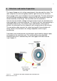
4 Structure and mode of operation
The torque flange consists of two separate parts: the rotor and the stator. The
rotor comprises the measuring body and the signal transmission elements.
Strain gauges (SGs) are installed on the measuring body. The rotor electronics
for transmitting the bridge excitation voltage and the measurement signal are
located centrally in the flange. The transmitter coils for contactless
transmission of excitation voltage and measurement signal are located on the
measuring body's outer circumference. The signals are sent and received by a
separable antenna ring. The antenna ring is mounted on a housing that
contains the electronics for the automatic self-tuning function of the antenna.
The connection cable connects the stator housing with the evaluation unit
which contains the electronics for voltage adaptation and the signal
conditioning.
Connectors and screw terminals for the torque signal and the voltage supply
are located on the evaluation unit. The stator antenna ring should be
mounted more or less concentrically with some gap to the rotor antenna
(see Chapter 5).
Fig. 4.1: Transducer with stator antenna and evaluation unit