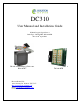
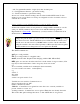
DC310 User Manual and Installation Guide K-Band Doppler Speed Sensor Built Type: DC310-DFT, DC310-OFD Rev 0, 10th April 2013 DC310 in Weatherproof Enclosure DC310-DFT Houston Radar LLC 12818 Century Dr. Stafford, TX 77477 Http://www.Houston-Radar.com Email: sales@Houston-Radar.
This device complies with part 15 of the FCC Rules. Operation is subject to the following two conditions: (1) this device may not cause harmful interference, and (2) this device must accept any interference received, including interference that may cause undesired operation. The device must be located 20 cm or more from persons. The device must not be co-located with other transmitters. These warnings must be included in the user manual of the final configuration where this device is utilized.
Note: Not liable for typographical errors or omissions.
Table Of Contents INTRODUCTION ......................................................................................................... 5 INSTALLATION .......................................................................................................... 5 MOUNTING................................................................................................................... 5 RECOMMENDED ENCLOSURE FOR THE DC310-OFD: ..................................................... 7 HOOKUP:.....................
INTRODUCTION Congratulations on your purchase of the Houston Radar directional Tracking Doppler Radar DC310. This state of the art 24GHz K-band microwave Doppler radar is specifically designed for the license free battery operated traffic monitoring and data collection market.
environment. The DC310-DFT should be mounted such that the text “Houston Radar” on the face of the unit is horizontal. Pick a location where the traffic is free flowing and the DC310 has at least 100 feet (30m) of unobstructed road in either direction. Avoid mounting within 100 feet (30m) of congestion points such as stop signs, sharp turns and traffic signals. Avoid mounting where trees, branches or other objects are obstructing the view of the traffic.
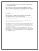
10 feet max 10 feet max 12 feet max Radar on side with 1 lane each direction Radar on side with 2 lanes incoming. No outgoing lanes can be detected Radar on single lane median with up to 2 lanes on each side Recommended Enclosure for the DC310-OFD: The DC310-OFD radar needs to be enclosed in a weatherproof enclosure for outside use. The following needs to be observed for optimal performance: 1.
Hookup: Power Input: The DC310 radar features wide operating input voltage range of 5.5V-18V. In a typical application it may be powered from a nominal 12V DC source and will feature best in class operational power consumption of 14 mA (average). There is no other radar in the world that even comes close to this ultra-low power usage. Competing products may consume up to 20 times more power.
“.ddd”: Programmable number of digits (0-3) after decimal point “\r”: Carriage Return character, optional line ending “\n”: Line Feed character, optional line ending At least one or both of the line endings must be selected with ASCII format. No line ending is not an option. Please see serial port configuration section for details on how to select the above format.
"ERROR" when you are not expecting them. To get a variable: get:[ENTER] e.g. get:LO returns LO=5 (if value is presently set to 5). If sending the ASCII command via an attached microcontroller, the “[ENTER]” key press should be replaced by the carriage return and/or line feed ASCII character.
Wire Signal Descriptions: Connector Pin # 1 Signal Name GND Direction Description PWR Radar GND (battery “–“ terminal) 2 N/C N/C Do not connect 3 4 I/O0 I/O1 I/O I/O Reserved for future use Reserved for future use 5 6 I/O2 I/O3 I/O I/O Reserved for future use Reserved for future use 7 Trig O/P 1 Output “Open Drain Output 1”. See Note 1. 8 Trig O/P 2 Output “Open Drain Output 2”. See Note 1.
Houston Radar DC310 User Manual USE Turn on the power to the DC310 to make it operational. No other action is required. The radar will activate the appropriate OUT 1 and OUT 2 open drain outputs, if enabled, whenever it detects a vehicle that is above the programmed lower speed limit (the “LO” value) and below the programmed high limit (the “HI” value). The default limits are set at 3 and 99 at the factory. The units (e.g. kph, mph, fps, mps) are determined by UN variable.
Houston Radar DC310 User Manual Internal Clock: The radar has a built in clock/calendar function. This allows the radar to date/time stamp the historical archive records saved by the Advanced In-Radar traffic statistics collection feature. The radar does not feature a clock backup battery. Power must remain connected to the radar for the clock to keep time. An external clock battery may be connected to keep time while radar goes into low power sleep mode. See Appendix C for more details.
Houston Radar DC310 User Manual Radar Configuration Variables Continued: Configuration Description Variable Name Target detection sensitivity. Valid values are from 10 to 100 and are a ST percentage of max magnitude. This value should be left at 100, unless the radar is over counting due to mounting location. Radar mode bitmask. Bits are as follows: MO Bit 0: SI3 ASCII command compat flag. Contact us for more details.
Houston Radar DC310 User Manual Configuring the Radar via the provided Houston Radar Configuration Tool GUI: 1. Install the provided Houston Radar Advanced Stats Analyzer (or Houston Radar Configuration) Windows program on a Windows 2000, XP, Vista or Win 7 computer. Both 32 and 64 bit operating systems are supported. 2. Connect the radar RS232 port to the PC’s RS232 serial port.
Houston Radar DC310 User Manual STEP 1: Connect to Radar Select your COM port (or “AutoDetect Port” option) and then click on “Connect To Radar”. Click “OK” on the next two boxes. The one on the left shows you information about the radar that you have connected to which you may ignore at this time.
Houston Radar DC310 User Manual STEP 2: Click on Radar Setup to bring up the configuration GUI Click on “Radar Setup” to bring up the GUI. You must click on “Write To Radar” button for your changes to be saved to the radar.
Houston Radar DC310 User Manual STEP 3: Select the radar units Radar units apply to the speed output over the RS232 serial port as well the low limit cutoff and high limit cutoff settings. Additionally, if traffic statistics gathering is enabled, statistics are saved in integer mph boundary speed bins for mph and ft/sec units and in km/h integer boundary speed bins for km/h or m/s units in the radar. Select radar units. Units may be set to one of the values shown.
Houston Radar DC310 User Manual STEP 4: Set the radar cutoff speeds (low and high speed cutoff) Cutoff speeds affect the measurement range for sending speed out over the serial port and activation of the hardware trigger outputs. Cutoff speeds will affect collection of traffic statistics for the DC310. Traffic statistics will not collected outside of the detection limits. Set the minimum speed you wish the radar to pick up and display. This is also the minimum speed that will activate the trigger outputs.
Houston Radar DC310 User Manual STEP 5: Configure the trigger outputs Detection Direction: Select “Incoming” to activate trigger for approaching targets and “Outgoing” to activate for receding targets. Both types cannot be selected. You may also enable active low output here.
Houston Radar DC310 User Manual STEP 6: Enable Average Speed Output Select this option to enable ASCII average speed output for both directions. You may also specify the averaging time in seconds.
Houston Radar DC310 User Manual STEP 7: Input Voltage and Ambient Temperature In this section, you can view the radar’s input voltage, and ambient temperature. Click “Read Now” to update these values.
Houston Radar DC310 User Manual DC310 SPECIFICATIONS General Operating Band Frequency RF Power Output Antenna Beam Pattern Polarization Supply Voltage Reverse Battery Nominal Current Draw Operating Temp. Weatherproof IR Remote Programmable K-Band 24.125 GHz ±50Mhz (US), 24.200Ghz on request 5mW 20deg x 60deg Linear 5.5V DC to 18V DC Protected 14 mA avg. (7mA-23mA depending on traffic) @+12V DC -22°F to +185°F (-30°C to +85°C). Electronics designed and tested to –40C. Yes (DC310-DFT build option).
Houston Radar DC310 User Manual Performance Speed Measurement Range 1.3mph to 100 mph (2.1km/h to 161 kph). Resolution ±0.006 mph Accuracy ±0.5% of reading + 0.1mph Detection Range Typically 75+ m (250+ feet) for compact vehicles on open and level road with radar mounted 1.5 m (5 feet) high and pointed straight into traffic. 150+ m (500+ feet) for larger trucks, lorries and vehicles with inherently large radar cross-section. May vary with installation and road conditions.
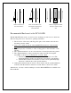
Houston Radar DC310 User Manual Appendix A: Hooking up to the trigger outputs on the radar The DC310 radar features two “open drain” outputs. The device used for this purpose is the On Semiconductor relay driver NUD3124. The output configuration of this device is shown below (from the On Semi datasheet). The two outputs O/P1 and O/P2 are brought out on the radar connector pins (see IO connector pin out in manual for connector pin numbers). This device can sink 130mA of DC current at up to 28VDC.
Houston Radar DC310 User Manual Appendix B: Optional Breakout IO Board Connections: (Non-Isolated Mosfet version with PWM Brightness Control) Connecting the load to the High power and trigger outputs: You may directly connect your high power DC load + & - to J5. The load is activated via fuse F1 when the output is triggered. You may directly connect a <150mA relay coil or other low power load to the J4 & J6 connectors. The + load terminals are always wired to VCC.
Houston Radar DC310 User Manual Optional Breakout IO Board Connections: (Isolated Solid-State Relay version, AC or DC capable) Optional Isolated IO Board. Note: PWM Brightness Control is NOT available with Isolated AC/DC Relay outputs.