Switch-Pad™ SVR-1 Step Voltage Regulator Instructions Installation, Operation, and Maintenance of SVR-1 Step Voltage Regulators Howard Industries, Inc. ISO-9001 Certified Document No. 2.4.114 Revision: 03 Issued: March, 2012 Copyright © 2012 Howard Industries, Inc.
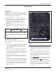
SVR-1 Step Voltage Regulator Document 2.4.114 READ THIS IMPORTANT SAFETY INFORMATION Read these instructions carefully and become familiar with the equipment before proceeding with installation, operation, or maintenance activities. This equipment contains extremely hazardous voltages. To prevent death, serious personal injury, or equipment damage, all information in these instructions should be read and observed.
Switch-Pad™ SVR-1 Step Voltage Regulator Table of contents Receiving Inspection, Storage, and Handling ........................................................................................................................... 4 Receiving Inspection ............................................................................................................................................................. 4 Handling . .........................................................................................
SVR-1 Step Voltage Regulator Document 2.4.114 receiving INSPECTION, STORAGE, AND HANDLING RECEIVING INSPECTION Immediately upon receipt the regulator should be carefully inspected for evidence of shipping damage. The shipping manifest should be checked to make sure all listed materials have been received. Any damage or material discrepancies should be noted on the shipping manifest and a claim should be immediately filed with the freight carrier.
Switch-Pad™ SVR-1 Step Voltage Regulator installation introduction An SVR-1 regulator can regulate the voltage on a singlephase circuit or one phase of a delta- or wye-connected three-phase circuit as described below and as illustrated in the connection diagrams on page 9.
SVR-1 Step Voltage Regulator Document 2.4.114 installation (Continued) INSTALLATION LOCATION SVR-1 regulators are designed for outdoor applications. Regulators with hanger brackets can be mounted on utility poles of the proper weight-bearing class. Regulators supplied with substation bases can be pedestal mounted. In addition, any regulator can be platform mounted.
Switch-Pad™ SVR-1 Step Voltage Regulator installation (continued) CONTROL CONNECTIONS SVR-1 regulators can be used on several different system voltages. A cover-mounted terminal block (Figure 3) is provided, so that control and fan leads (if present) can be connected as necessary to accommodate the particular system voltage to be regulated. SVR-1 regulators may be operated at less than the rated voltage as indicated on the nameplate.
SVR-1 Step Voltage Regulator Document 2.4.
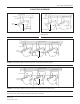
Switch-Pad™ SVR-1 Step Voltage Regulator CONNECTION diagrams Neutral Bypass Switch Disconnects Disconnects S Shunt Arrester Bypass Switch A B C LOAD load SOURCE Bypass Switch Sl Series Arrester L L S S SL SL 1 Series Arrester 2 SOURCE Bypass Switch* A B C N Bypass Switch* Bypass Switch* LOAD FIGURE 6: Two SVR-1 regulators in an open delta threephase system.
SVR-1 Step Voltage Regulator Document 2.4.114 PLACING A REGULATOR IN SERVICE PROCEDURE FOR PLACING IN SERVICE After completing the installation procedure outlined in the previous section, the regulator can be placed into service using the following procedure. 1. Set HI-AMP™ limits, if necessary, using the rotary switches located on either side of the position indicator (Figure 9). The HI-AMP™ feature allows the SVR-1 regulator to be operated above rated load by decreasing the range of operation in 1.
Switch-Pad™ SVR-1 Step Voltage Regulator PLACING A REGULATOR IN SERVICE (continued) CHECKING FOR PROPER OPERATION Refer to the control unit instruction manual and use the following procedure to check for proper regulator operation. (Switch designations referenced below are applicable to the HI/ICMI control.) 3. Set the MOTOR CONTROL AUTO/MANUAL switch to the “AUTO” position. After a time delay, the regulator will automatically return to an IN-BAND condition.
SVR-1 Step Voltage Regulator Document 2.4.114 rEMOVING A REGULATOR FROM SERVICE The following procedure should be used to remove a regulator from service. For additional information refer to the manual supplied with the control unit (Switch designations referenced below are applicable to the HI/ICMI control.). 1. Set MOTOR CONTROL AUTO/MANUAL switch to MANUAL position. 2.
Switch-Pad™ SVR-1 Step Voltage Regulator Maintenance GENERAL INSTRUCTIONS SVR-1 step voltage regulators are designed for long life and trouble-free operation. Periodic inspection and maintenance will prolong life and minimize the likelihood of service interruptions. Proper operation can be checked without removing the regulator from service. Follow the procedures in this section to perform in-service inspection and maintenance.
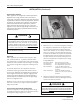
SVR-1 Step Voltage Regulator Document 2.4.114 Maintenance (continued) If the regulator is not operating properly, the first step in troubleshooting should be the replacement of the control unit with one known to be in good operating condition. warning Dangerous voltage is present at the Connector Terminal Strip and the motor capacitor terminals. Contact with these voltages inside the control enclosure can cause death or serious personal injury.
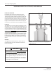
Switch-Pad™ SVR-1 Step Voltage Regulator Maintenance (Continued) before beginning untanking procedures. • Remove the control cable from the terminal block enclosure and, if necessary, the control box from the tank. • Loosen the cover band and remove it from the regulator. • The regulator can now be removed from the main tank using the cover lifting eyes (Figure 11). 2. Check to verify all hardware and connections are tight. 3.
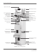
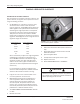
SVR-1 Step Voltage Regulator Document 2.4.114 Parts List 151 020 015 015 163 158 004 057 160 161 003 003 060 FIGURE 12: External Parts View - refer to Table 1 on the following page for parts description. 16 Copyright © 2012 Howard Industries, Inc. Document No. 2.4.
Switch-Pad™ SVR-1 Step Voltage Regulator Parts List (Continued) TABLE 1: External Parts - (Refer to Figure 1 on the previous page) Item REFERENCE DESCRIPTION 003 Nameplate 004 Pressure Relief Valve 015 Bushing Assembly (“S” or “SL” with standard mounting clamp) 020 Bushing Assembly (“L” with CT mounting clamp) 057 Oil Level Sight Gauge 060 Drain Valve with Sampling Device 151 By-Pass Arrester Assembly 158 Position Indicator 160 Flexible Conduit Assembly 161 Control Enclosure 163 T
SVR-1 Step Voltage Regulator Document 2.4.114 SVR-1 Step Voltage Regulator Installation, Operation, and Maintenance Instructions Document No. 2.4.114, Revision 3, March 2012 Copyright © 2012 Howard Industries, Inc. Laurel, Mississippi Telephone: 601-425-3151 Fax: 601-649-8090 Web howardtransformers.com 18 Copyright © 2012 Howard Industries, Inc. Document No. 2.4.