
Manual
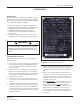

Switch-Pad™ SVR-1 Step Voltage Regulator
Document No. 2.4.114
Revision: 03
Issued: March, 2012
3
Copyright © 2012 Howard Industries, Inc.
TAblE OF CONTENTS
Receiving Inspection, Storage, and Handling .......................................................................................................................... 4
Receiving Inspection ............................................................................................................................................................ 4
Handling ................................................................................................................................................................................ 4
Storage .................................................................................................................................................................................. 4
Installation .................................................................................................................................................................................. 5
Introduction .......................................................................................................................................................................... 5
Pre-Installation Checklist ..................................................................................................................................................... 5
Installation Location ............................................................................................................................................................. 6
Mounting ............................................................................................................................................................................... 6
High-Voltage and Grounding Connections .......................................................................................................................... 6
Control Connections ............................................................................................................................................................. 7
Bypass Surge Arrester .......................................................................................................................................................... 7
Lightning Protection ............................................................................................................................................................. 7
Through Fault ........................................................................................................................................................................ 7
50 Hertz Operation .............................................................................................................................................................. 7
Placing a Regulator in Service ................................................................................................................................................. 10
Procedure ............................................................................................................................................................................ 10
Checking for Proper Operation .......................................................................................................................................... 11
Removing a Regulator from Service ...................................................................................................................................... 12
Procedure ........................................................................................................................................................................... 12
Returning a Regulator to Service .................................................................................................................................... 12
Maintenance ........................................................................................................................................................................... 13
General Instructions .......................................................................................................................................................... 13
Operational Checks ........................................................................................................................................................... 13
Insulation Fluid ................................................................................................................................................................... 14
Internal Inspection ............................................................................................................................................................. 14
Vacuum Oil Fill Process ........................................................................................................................................................15
Cooling Fans ....................................................................................................................................................................... 15
External Parts List ................................................................................................................................................................ 16-17
lIST OF FIGURES
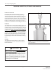
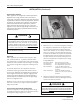
Figure 1: Recommended method for lifting regulator ....................................................................................................... 4
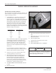
Figure 2: Typical regulator nameplate ................................................................................................................................ 5
Figure 3: Cover-mounted terminal block ............................................................................................................................. 6
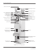
Figure 4: SVR-1 step voltage regulator .............................................................................................................................. 8
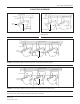
Figure 5: Connection diagram, one SVR-1 regulator in a single-phase system ............................................................... 9
Figure 6: Connection diagram, two SVR-1 regulators in an open delta three-phase system .......................................... 9
Figure 7: Connection diagram, three SVR-1 regulators wye connected in a three-phase four-wire system ................... 9
Figure 8: Connection diagram, three SVR-1 regulators delta connected in a three-phase three-wire system
........................ 9
Figure 9: HI-AMP™ switches .............................................................................................................................................. 10
Figure 10: Connector terminal strip (CTS) ........................................................................................................................ 14
Figure 11: Recommended lifting method for untanking regulator internal assembly .................................................. 15
Figure 12: External parts view ........................................................................................................................................... 16