
Manual

Switch-Pad™ SVR-1 Step Voltage Regulator
Document No. 2.4.114
Revision: 03
Issued: March, 2012
5
Copyright © 2012 Howard Industries, Inc.
INTRODUCTION
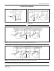
An SVR-1 regulator can regulate the voltage on a single-
phase circuit or one phase of a delta- or wye-connected
three-phase circuit as described below and as illustrated
in the connection diagrams on page 9.
One SVR-1 regulator in a single-phase application
Three SVR-1 regulators connected in a grounded wye
conguration on a four-wire three-phase system
Three SVR-1 regulators connected in a delta
conguration on an ungrounded three-wire three-
phase system
Two SVR-1 regulators connected in an open delta
conguration on an ungrounded three-phase system
INSTAllATION
PRE-INSTAllATION CHECklIST
Before connecting the regulator, the following checks
should be made:
1. Check the oil level sight gauge for proper oil level (top
oil level visible in gauge). Add ASTM D-3487 Type 2
oil, if the level is found to be low. Check for visible
signs of oil leaks.
2. Measure the dielectric strength of the oil per ASTM
D-877. If found to be below 24 kV, the oil should be
ltered and retested (NOTE: This test is not necessary
if the regulator is being installed immediately after
receipt from the factory.)
3. Measure power factor from each bushing terminal
to tank ground. The reading should be less than 2.0
percent.
4. Inspect the porcelain bushings for damage or signs
of oil leaks. If it is suspected that moisture may have
entered the regulator, test the oil per ASTM D-3487
(Type 2). A positive indication for moisture will require
that the regulator be dried and the oil ltered before
placing into service.
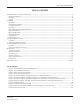
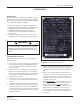
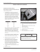
FIGURE 2: Typical regulator nameplate
WARNING
Due to the possibility of neutral shift, three SVR-1
regulators should not be connected together in an
ungrounded, wye-connected, three-wire, three-phase
system.
5. Inspect the by-pass arrester (and shunt arresters, if
present) for damage. Damaged arresters should be
replaced with new arresters of the same voltage rat-
ing.
6. Refer to the nameplate (Figure 2) and conrm that
the regulator is connected for the proper output volt-
age, motor voltage, and control panel voltage. If not,
follow the procedure on pages 6 and 7 to make the
necessary connections.
7. Make absolutely sure that the regulator tap changer
is in the neutral tap position. This can be accom-
plished by observing that both of the following
conditions have been met: 1) The pointer on the tap
position indicator is pointing to “zero,” and 2) the
neutral indicator is continuously illuminated. (The
control panel can be powered from a 120 Volt exter-
nal source.)