
User Manual

Dwg No:60031:0 Iss 3 Apr 2001
MG212000
MG212100
Complies with Council
Directive 89/336/EEC
16 v.a.c
INPUT
F2 Auto or remote RESET. Apply +ve
F1 Auto or reomte SILENCE. Apply +ve
F3 ISOLATE functions. Apply +ve
Link F4 to +ve to change I1 - I6 from N.C. to N.O.
N
E
L
Mains Fuse
These components are
only fitted in the
MG2121XX and
MG2161XX versions.
The MG2120XX and
MG2160XX versions
should be powered from
an external power
supply connected to
any unused +ve & -ve
terminals.
240/220
vac
50Hz
Apply +ve to
activate function
The standby battery is connected
via a polarised socket on the
reverse of the p.c.b.
12 volt 0.8 Ahr standby battery
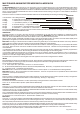
IT IS IMPORTANT THAT THE MULTIGUARD IS FIXED TO A FLAT SURFACE. IF THE BOX DISTORTS IT WILL
BE DIFFICULT TO CLIP THE VARIOUS COMPONENTS TOGETHER TO FORM A SECURE HOUSING.
Connection & Power Up sequence.
The MULTIGUARD has a short test or verification sequence on power up. You should verify that the unit as supplied is functioning normally
before making any connections.
1. Plug in the battery. The plug is polarised to maintain the correct polarity. Ensure F4 is linked to +ve. The integral sounder will beep at 1 second
intervals.
MG212XXX
2a. Press the SILENCE button F1. The LED's will flash twice and then remain steady. Press the RESET button F2. The unit is now ready to
accept connections.
MG216XXX
2b. Press any button Z1 -Z6. The LED's will flash six times and then extinguish. The unit is now ready to accept connections.
3. Connect the 220/240vac mains to the Live, Neutral & Earth terminals. Ensure the mains fuse is fitted and the transformer leads (Blue &
Yellow) and earth lead (Green) are connected to the PCB.
4. Clip the PCB assembly onto the back box.
5. Switch on the power. Observe the green Mains On LED.
6. Dress the cable into the cable channel, trim to length and terminate as appropriate. Remove link F4 if monitoring closed circuits.
7. The system can now be tested and the decal and lid clipped into place.
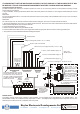
- + 1 2 3 4 5 6 + + 1 2 3 4 5 6 + + 1 2 3 4 + -
- + X S D C
INPUTS
SERIAL
OUTPUT
RELAY
OUTPUT
ZONE RESETS FUNCTION
INPUTS
Multicore cable
to repeaters, relay
or interface cards
See MG226000
instructions
Voltage monitoring with respect to -ve (1.5 - 30Vdc)
Link un-used
inputs to +ve
if configured
for N.C. I/Ps
-
+
Closed or open circuit contacts
Remote zone control. Apply momentary +ve to Z1 - Z6
M
To EXITGUARD
All terminals marked +ve & -ve form a
common power supply feed. They can
be used for dc in or out. However, Do
not apply 12 volts dc to these terminals
on mains powered (ie. MG2121XX or
MG2161XX) versions
POWER SUPPLY
The integral 13.8vdc power supply (if fitted) is rated at 250ma., and is supplied with a rechargeable 0.7 Ahr standby battery. The
MULTIGUARD circuitry has a maximum power requirement of 60ma . The integral power supply will therefore support its own six zone
electronics plus a further three units or repeaters and/or relay cards.
T. 01744 886600 F. 01744 886607 E. sales@hoyles.com W. www.hoyles.com
Hoyles Electronic Developments Ltd