
User guide

LED
LED
+ve
A
B`
B``
-ve
+ve
A
B`
B``
-ve
+ve
A
B`
B``
-ve
+ve
A
B`
B``
-ve
+ve
A
B`
B``
-ve
+ve
A
B`
B``
-ve
NPN
PNP
S312 Series Interface Relays
These transistorised relays are designed as general
purpose interface devices. Double pole changeover
contacts rated at 2A 30vdc 0.5A 120vac are provided.
The circuit board also carries an LED to indicate when
the relay coil is energised. The coil is suppressed
against back emf and diode protection is given against
reverse polarity.
There are three versions available for either 12 or 24v
dc power.
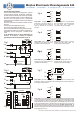
S312 N / N24 uses a NPN transistor Fig 1
S312 P / P24 uses a PNP transistor Fig 2
S312 T / T24 as NPN with RC timing components Fig 1
A self adhesive backing is provided for rapid fixing or
alternatively the four fixing holes provided can be
used.
In the examples 12vdc or 24vdc (Depending on
version of product), should be applied
permanently to the terminals marked +ve & -ve
S312T additional
components
S312 P/P24 Applying a +ve signal greater
than 8v to either B` or B`` will de-energise
the relay. When both e signals are
removed the relay will re-energise.
S312 N/N24 Applying a +ve signal
greater than 4v (eg TTL) to either B` or
B`` will energise the relay. When the
signal is removed the coil will de-
energise.
S312 N/N24 Closing switch S will
energise the relay. When switch S is
opened the relay will de-energise.
S312 P/P24 Closing switch S will de-
energise the relay. When switch S is
opened the relay will re-energise.
S312 N/N24 Closing switch S will de-
energise the relay. When switch S is
opened the coil will energise.
S312 P/P24 Closing switch S will
energise the relay. When switch S is
opened the relay will de-energise.
S312 N/N24 connected as a latching relay. P1 and P2 are Normally Open
pushbuttons. When P1 is pressed the relay will energise and remains energised. To
de-energise the relay press P2
S312 T/T24 uses an NPN transistor and is fitted with additional components (see Fig
1). When the switch S is closed the capacitor is charged almost immediately and the
relay coil energises, If switch S is then opened the voltage across the capacitor falls
and eventually the coil of the relay de-energises. The discharge period can be varied
by the on board potentiometer. The delay that can be achieved is from a minimum of
approximately 3 seconds to a maximum of 60 seconds. Do NOT connect B` or B`` to
+ve. The contacts should be derated by 50% because of the slow release time. Hoyles
Electronic Developments also manufacturer timers with better resetting accuracy and
timing ranges up to 2 hours.
s
s
s
+ve
A
B`
B``
-ve
P1
P2
*
+
A
B`
B``
-
47 mm
52 mm
16 mm
Fig 1
Fig 2
Fig 3
Fig 4
Fig 5
Fig 8
Fig Fig 6
Fig 7
w:\Tech\S312 interface relays\Common\Installation Instructions\60071.cdr April 2010 Iss 3
LED
Pot
T. 01744 886600 F. 01744 886607 E. sales@hoyles.com W. www.hoyles.com
Hoyles Electronic Developments Ltd