Service Manual HP DesignJet 2000CP HP DesignJet 2500CP HP DesignJet 2800CP HP DesignJet 3000CP HP DesignJet 3500CP HP DesignJet 3800CP Printers
For HP Internal Use Only Warranty WARNING E Copyright HewlettPackard Company 1998 The information contained in this document is subject to change without notice. The procedures described in this manual are to be performed by HP-qualified service personnel only. This document contains proprietary information that is protected by copyright. All rights are reserved.
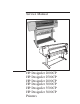
Service Manual HP DesignJet 2000CP HP DesignJet 2500CP HP DesignJet 2800CP HP DesignJet 3000CP HP DesignJet 3500CP HP DesignJet 3800CP Printers
Using this Manual Purpose This manual contains information necessary to test, calibrate and service: D HP DesignJet 2000CP printer (model C4703A) D HP DesignJet 2500CP printer (model C4704A) D HP DesignJet 2800CP printer (model C6085A) D HP DesignJet 3000CP printer (model C4723A) D HP DesignJet 3500CP printer (model C4724A) D HP DesignJet 3800CP printer (model C6084A) For information about using these printers, refer to the corresponding user and quick-reference guides.
Contents Using this Manual . . . . . . . . . . . . . . . . . . . . . . . . . . . . . . . . . . . . . . . . . . . . . . . . . ii Safety Symbols . . . . . . . . . . . . . . . . . . . . . . . . . . . . . . . . . . . . . . . . . . . . . . . . . . . . . x 1 Troubleshooting Which Firmware relates to which Ink system? . . . . . . . . . . . . . . . . . . . . . . . . . . . How do I Check the Hard Disk Drive Version? (Only applicable to HP DesignJet 2500CP/3500CP) . . . . . . . . . . . . . . . . . . . . . . .
2 System Error Codes System Error: 0000D8 XXXXXXXX . . . . . . . . . . . . . . . . . . . . . . . . . . . . . . . . . . . . . System Error: 010020 . . . . . . . . . . . . . . . . . . . . . . . . . . . . . . . . . . . . . . . . . . . . . . . . . . System Error: 010021 AXXXXXXX . . . . . . . . . . . . . . . . . . . . . . . . . . . . . . . . . . . . . System Error: 010022 . . . . . . . . . . . . . . . . . . . . . . . . . . . . . . . . . . . . . . . . . . . . . . . . . . System Error: 010023 . . . . . . . . .
System Error: 090004 . . . . . . . . . . . . . . . . . . . . . . . . . . . . . . . . . . . . . . . . . . . . . . . . . . 2-31 Error Message: Ink System Error XX-YYYY . . . . . . . . . . . . . . . . . . . . . . . . . . . . . 2-31 3 User Messages User Messages for HP DesignJets 2500CP and 2000CP with Firmware Version A.02.14 or Higher and HP DesignJets 3500CP and 3000CP . . . . . . . . 3-2 4 Service Tests Introduction . . . . . . . . . . . . . . . . . . . . . . . . . . . . . . . . . . . . . . . . . . . .
6 Image Quality Image Quality Troubleshooting Checklist . . . . . . . . . . . . . . . . . . . . . . . . . . . . . . . . Print Modes . . . . . . . . . . . . . . . . . . . . . . . . . . . . . . . . . . . . . . . . . . . . . . . . . . . . . . . . . . . Image Quality Print . . . . . . . . . . . . . . . . . . . . . . . . . . . . . . . . . . . . . . . . . . . . . . . . . . . Introduction . . . . . . . . . . . . . . . . . . . . . . . . . . . . . . . . . . . . . . . . . . . . . . . . . . . . . . .
Additional Rear Cover (Only applicable to HP DesignJets 3500CP and 3000CP) . . . . . . . . . . . . . . . . . . Removal . . . . . . . . . . . . . . . . . . . . . . . . . . . . . . . . . . . . . . . . . . . . . . . . . . . . . . . . . . . Installation . . . . . . . . . . . . . . . . . . . . . . . . . . . . . . . . . . . . . . . . . . . . . . . . . . . . . . . . Hard Disk Drive, Power Switch Cable . . . . . . . . . . . . . . . . . . . . . . . . . . . . . . . . . . . Removal . . . . . . . . . . . . . . . . . .
Refill Assembly . . . . . . . . . . . . . . . . . . . . . . . . . . . . . . . . . . . . . . . . . . . . . . . . . . . . . . . . Removal . . . . . . . . . . . . . . . . . . . . . . . . . . . . . . . . . . . . . . . . . . . . . . . . . . . . . . . . . . . Installation . . . . . . . . . . . . . . . . . . . . . . . . . . . . . . . . . . . . . . . . . . . . . . . . . . . . . . . . Bail Assembly and Star Wheel Assemblies . . . . . . . . . . . . . . . . . . . . . . . . . . . . . . . Removal . . . . . . . . . . . .
Noisy Carriage Bushing . . . . . . . . . . . . . . . . . . . . . . . . . . . . . . . . . . . . . . . . . . . . . . . . Belt Swelling . . . . . . . . . . . . . . . . . . . . . . . . . . . . . . . . . . . . . . . . . . . . . . . . . . . . . . . . . . Cleaning the Printer . . . . . . . . . . . . . . . . . . . . . . . . . . . . . . . . . . . . . . . . . . . . . . . . . . . General Cleaning . . . . . . . . . . . . . . . . . . . . . . . . . . . . . . . . . . . . . . . . . . . . . . . . . .
General Definition of Safety Symbols International caution symbol (refer to manual): the product is marked with this symbol when it is necessary for the user to refer to the instruction manual in order to protect against damage to the instrument. Indicates dangerous voltage (terminals fed from the interior by voltage exceeding 1000 volts must also be marked). OR Protective conductor terminal. For protection against electrical shock in case of a fault.
1 Troubleshooting HP DesignJet CP Series Printers 1-1
Introduction This chapter will guide you through the relevant steps to take when troubleshooting the printer. Which Firmware relates to which Ink system? A.01.XX - This firmware revision is applicable to HP DesignJets 2500CP and 2000CP and means that the Printers can only use Imaging Inks. A.02.XX - This firmware revision is applicable to HP DesignJets 2500CP and 2000CP and means that the Printers can use both the Imaging Inks and the new UV Durable Inks. A.03.
How do I upgrade the Firmware Revision on the Flash SIMM? You will need to have the Printer connected to a PC or a UNIX Workstation with a Parallel cable. Download the latest Firmware Revision from the Plotter Support WEB to your local drive and then follow these instructions: 1 Make sure the printer is switched OFF from the power switch on the back of the printer and not from the standby button on the front of the printer. 2 Hold the CANCEL key down and switch the printer ON.
9 While the firmware data is being received by the printer, the message “Receiving Binary Code” will be displayed on the front-panel. THE DATA IS BEING DOWNLOADED ONTO THE FLASH SIMM AT THIS POINT. DO NOT SWITCH OFF THE PRINTER BECAUSE IT WILL DAMAGE THE FLASH SIMM. 10 When the Flash SIMM is completely programmed, the message “Finished Programming / Power OFF the board” will be displayed on the front-panel. 11 Switch the Printer OFF from the power switch on the back of the printer.
8 When the data on the Flash SIMM is erased the message “Please Download Binary Code” is displayed on the front-panel. 9 To download the PostScript data to the Flash SIMM follow these instructions: If using a UNIX Workstation, type: $ cat filename > device.file Substitute “filename” with the name of the file that contains the PostScript data which you downloaded from the Plotter Support WEB. Substitute “device.file” with the name of your Workstation parallel device file.
How can I Copy Firmware Data from One Flash SIMM to a Second Flash SIMM? This procedure can be used to copy Data from one Flash SIMM to another. This is very useful when you have to update the Firmware Revision of several Printers and is much faster than updating from the PC. 1 Make sure the printer is switched OFF from the power switch on the back of the printer and not from the standby button on the front of the printer. 2 Remove the SIMM cover on the back of the Electronics Module.
What Can I do when a System Error Code Appears on the Front-Panel Display? Chapter 2 contains a list of system error codes and their respective descriptions and recommended corrective actions. Only try one recommended action at a time and check if the error code has disappeared. If you have an error code which is not documented in this Service Manual or you have an error which you cannot resolve, then report the error to the HP Response Center or the nearest HP Support Office.
Have you Performed the Necessary Service Calibrations? Is the printer calibrated correctly after replacing a component? Refer to the table below to determine when a calibration is required. For information on the Service Calibrations and how to use them Chapter 5. REMEMBER THAT CERTAIN CALIBRATIONS ARE REQUIRED EVEN IF AN ASSEMBLY HAS BEEN DISASSEMBLED TO GAIN ACCESS TO ANOTHER ASSEMBLY OR COMPONENT.
What can I do if the Carriage is Noisy? 1 Dirty Carriage bushings. Remove dust particles from the Carriage bushings and from the slider rods along which the Carriage moves. If necessary, apply lubricant to the slider rods. 2 Check for a faulty Carriage. Perform the Carriage Axis Test page 4-12. What can I do if the Service Station is Noisy? 1 Dirty Service Station slider rod. Remove dust particles from the Service Station slider rod along which the Service Station moves.
What can I do if the Cover Sensors aren’t Working? 1 Check if the faulty sensor is installed correctly. 2 Check if the cable for the faulty sensor is connected correctly. 3 Replace the faulty Sensor. What can I do if the “Switch Power Off / Check Printhead Path” message appears when the Printer is about to cut or is cutting? 1 Check the media path and clear it if necessary. 2 Perform the Cutter Test ' page 4-24. 3 Replace the Cutter Assembly ' page 8-48.
3 Is the client using Best Mode on Coated Media in high humidity? In this particular case, head crashes could occur due to worst casing. Recommend a change of media, print mode, or humidity conditions. 4 What is the Firmware Revision? (Only applicable to HP DesignJets 2500CP and 2000CP) Must be A02.01 or more recent. If not, upgrade. Explanation - In earlier releases of firmware a media jam/head crash can be caused at the start of a plot.
7 Replace the Overdrive Assembly and the Clutch ' page 8-69. D Explanation - For a unit fabricated before September of 1997 the clutch could cause intermittent media jams. Refer to the applicable Service Note. For a printer fabricated before July 1997 the linear blade could be too high, causing media jams. 8 Check for missing/blocked starwheels or starwheel mount assemblies. D Explanation - These parts can lead to media jams if missing or blocked.
2 The lens cover, which is installed on the line sensor, is dirty. Replace the lens cover Users Guide, Chapter 10 (Lens Maintenance). 3 The Line Sensor is not calibrated correctly. Perform the Line Sensor calibration page 5-10. 4 The Line Sensor is installed incorrectly. Try to reinstall it and make sure that it is connected and seated correctly. If the problem continues, replace the Carriage Assembly page 8-42.
What is the Ink System? For each of the four colors of ink in your printer’s ink system, there are three separate components that work together as a system. The components for each ink color are color-coded to help you install them correctly. Ink Cartridge The ink cartridges are a large-capacity ink supply from which the printheads are refilled whenever the ink volume in the printhead drops below a minimum level.
2 Reinstall the Ink Delivery System as follows: 1 Remove the four printheads from the carriage. On the front panel you will see the four squares representing the printheads flashing. 2 Clean the electrical contacts using the Ink Cleaner Part Number C6247A. 3 Reinstall all the printheads, one by one, checking on the front panel that the squares representing the reinstalled printheads are steady. D DO NOT INSERT THE NEXT PRINTHEAD UNTIL THE PRINTER HAS ACCEPTED THE CURRENT PRINTHEAD.
Does the Customer have Mid-Print Refill Problems in HP DesignJets 3500CP/3000CP? New Refill Features in HP DesignJet CP Series (in the case of DesignJets 2X00CP, the firmware release must be at least A.04.05) 1 Adaptive trigger. The printer looks for low density places to stop and refill in the print where it will be less noticeable. This feature becomes active when 75% of the ink in the printhead has been used up. RIP’s may have disabled this feature, or enabled it at a different ink level.
Troubleshooting Table 1 Problem Hazy stripe in Light line, dark or black any media area with Hi/Semi Gloss Photo Try higher Solutions Check that black contains image quality undercolor setting (send RGB to printer, or add 33% CMY to black areas yourself) Make sure type B or default refill is selected Switch between Type A and B refills High Gloss/ Semi Gloss Photo problems Non-HP medias Try higher image quality setting Try different refill types A,B or C Make sure type B or default refill is selecte
Refill Avoidance Tips Printer: 1 Try to “top off” printheads before large prints with “Refill Now” option in Front Panel (Image Quality / Printhead Service / Refill now). If a refill happened at the end of the last print (usually happens with big prints), this is not necessary. 2 If you have just canceled a print, you may need to use the “refill now” option to guarantee the maximum ink available for the next print. Print Composition Tips: 1 Don’t try to nest more than 15 ft^2 of prints.
How Do I Print some of the Internal Prints? The Service Print The purpose of the Service Print is to give information about the operating conditions, Usage Level, Serviceability and the MIO Configuration. This Print is very useful when troubleshooting the Printer, as it gives you information regarding the firmware revision, the last system error and the internal sensors. If the EEROM is cleared, you will loose all the information on the Service Print (including the MIO Configuration).
The Usage report The purpose of the Usage Report is to give information about some of the Internal Counters which can help you to know the usage of the Printer. If the EEROM is cleared, the counters will be reset to zero. Print the Usage Report as follows: Load media (A4 minimum) before printing the Usage Report. 1 In the Internal Prints submenu, scroll to “Usage Report” and press Enter. INTERNAL PRINTS Usage Report 2 The Usage Report will then be printed.
The PostScript Config The purpose of the PostScript Config is to give information about the internal Hard Disk, Internal Fonts and the PostScript part of the front-panel configuration. Print the PostScript Config as follows: Load media (A4 minimum) before printing the PostScript Config. 1 In the Internal Prints submenu, scroll to “PostScript Config” and press Enter. INTERNAL PRINTS PostScript Config 2 The PostScript Config will then be printed.
How to Navigate through the Front-Panel Menu ÇÇÇÇÇÇÇ ÇÇÇÇÇÇÇ ÇÇÇÇÇÇÇ Move Media ÊÊÊÊÊÊ ÊÊÊÊÊÊ ÊÊÊÊÊÊ ÊÊÊÊÊÊ ÇÇÇÇÇÇ ÇÇÇÇÇÇ ÇÇÇÇÇÇ ÇÇÇÇÇÇ ÇÇÇÇÇÇ Max X= Max Y= Code rev= PS rev= Disk rev= RAM present= Ink= Media= ÇÇÇ ÇÇÇ ÊÊÊ ÊÊÊ ÊÊÊ ÊÊÊÊÊ ÇÇÇÇÇ ÊÊÊÊÊ ÇÇÇÇÇ ÊÊÊÊÊ Applicable only to DesignJets 3XXXCP Applicable only to DesignJets 2XXXCP On Off* Continued on Next Page 1-22 HP DesignJet CP Series Printers Troubleshooting
Continued from Previous Page ÇÇÇÇÇÇÇÇÇÇÇ ÇÇÇÇÇ ÇÇÇÇÇÇ ÇÇÇÇÇÇÇÇÇÇÇ ÇÇÇÇÇÇÇÇÇÇÇ ÇÇÇÇÇÇÇÇÇÇÇ ÇÇÇÇÇÇ Take up reel=–> Refill=–> On* Off Default* Type A Type B Type C ÇÇÇÇÇ ÇÇÇÇÇÇÇÇÇÇÇ ÇÇÇÇÇÇÇÇÇÇÇ ÇÇÇÇÇ Extrawide–> ÇÇÇ ÇÇÇ Troubleshooting HP DesignJet CP Series Printers 1.0x1.4m 1.2x1.7m 44x62in. 52x73in. 54x76in.
2 System Error Codes HP DesignJet CP Series Printers 2-1
System Error Codes System error codes are hexa-decimal based numbers generally caused by internal system errors. The following pages contain a list of system error codes and their respective descriptions and recommended corrective actions.
Important Information on Troubleshooting Error Codes Before spending time troubleshooting the problem by doing the various tests or replacing parts (which may not need replacing), check which firmware revision the printer is using or check if a service note deals with this particular problem. Some problems which occurred in earlier firmware releases may have been solved in later revisions. So if there is a new firmware revision then update the Flash SIMM before replacing any parts.
System Error: 010021 AXXXXXXX Problem Description: The base DRAM or the RAM SIMM tests failed. Corrective Action: Try the following: NOTE: The Printer will not function without any RAM SIMMs installed. Make sure that you have a minimum of 4MB memory module installed. D If the Error Data is higher than A4000000 then the failure is in the RAM SIMM. Try the following to solve the problem. S Check that the RAM SIMMs (memory modules) are the original HP supported parts.
System Error: 010023 Problem Description: A fuse on the Main PCA has blown. Corrective Action: Try the following: D Check the X-encoder and optical sensors cable path for damage. If the cables are damaged, they could cause the fuses in the new electronics module to also blow. D Replace the Electronics Module ' page 8-6. System Error: 010024 Problem Description: Problem initializing the encoder pulse generator. Corrective Action: Replace the Electronics Module ' page 8-6.
System Error: 010030 Problem Description: One of the two interconnect boards not detected. Corrective Action: Try the following: D Make sure that the Interconnect Cables (the two black cables that connect the Refill Assembly and the Service Station Assembly to the Electronics Module) are correctly connected to the Electronics Module. D Replace the interconnect cables: S Service Station Interconnect Cable ' Page 8-87. S Refill Interconnect Cable ' Page 8-87. D Replace the Refill Interconnect PCA ' page 8-64.
System Error: 010031 Problem Description: The Printhead Primitive Driver ASIC Test Failed. Corrective Action: Try the following: D Make sure that the Trailing Cable is connected correctly. D Perform the Carriage Calibration ' page 5-7. D Replace the Trailing Cable ' page 8-36. D Replace the Carriage Assembly ' page 8-42. D Replace the Electronics Module ' page 8-6. Only replace one component at a time and check if the error has gone before replacing another component.
System Error: 010032 000000XX Problem Description: Fan Test Failed - Current not detected in one or both fans. Error data (XX): 1 ³ Electronics Module fan not running. 2 ³ Service station fan not running. 3 ³ Both fans not running. 10 ³ Electronics Module fan is short-circuited. 20 ³ Service Station fan is short-circuited. 30 ³ Both fans are short-circuited. 12 ³ Service Station fan is not running and the Electronics Module fan is short-circuited.
System Error: 010033 Problem Description: The DC Motor Driver ASIC Test Failed. Corrective Action: Replace the Electronics Module ' page 8-6. System Error: 010034 000X0000 Problem Description: One of the DC Motors has failed. Error data: 00010000 ³ Y-axis Motor Failed. 00020000 ³ X-axis Motor Failed. 00030000 ³ Both DC Motors Failed. Corrective Action: Try the following: D Make sure that both DC Motors are connected correctly.
System Error: 010035 0XABCDEF Problem Description: One of the Stepper Motors has failed. Error data (0XABCDEF): If the value of each letter is 0, then the component is OK. If the value of each letter is different from 0 then the component has failed. X ³ Electronics signal failed (ignore other values). A ³ Elevator Stepper Motor Failed. B ³ Refill Stepper Motor Failed. C ³ Primer Stepper Motor Failed. D ³ Service station (Z-axis) Stepper Motor Failed. E ³ Service station (X-axis) Stepper Motor Failed.
D If the Error is related to the Refill Stepper Motor then replace the Refill Assembly ' Page 8-55. D If the Error is related to the Primer Stepper Motor then replace the Primer Assembly ' Page 8-29. D If the Error is related to the Service Station Stepper Motors then replace the Service Station Assembly ' Page 8-26. D If the Error is related to the Bail Stepper Motor then replace the Bail Stepper Motor Assembly ' Page 8-62. D Replace the Electronics Module ' page 8-6.
S Replace the Electronics Module ' page 8-6. Only replace one component at a time and check if the error has gone before replacing another component. Using this procedure you will be able to determine exactly which component failed. System Error: 010036 0000XX00 Problem Description: A short circuit in the Y/X-axis or ANY stepper motor. This short circuit is causing some of the fuses in the Electronics Module to burn. Error data: 00000800 ³ Problem with the Y-axis. 00001000 ³ Problem with the X-axis.
Primer 46 20% Elevator 52 20% System Error: 010037 Problem Description: ADC Test Failure in the Carriage PCA. Corrective Action: Try the following: D Make sure that the Trailing Cable is connected correctly. D Replace the Trailing Cable ' page 8-36. D Replace the Carriage Assembly ' page 8-42. D Replace the Electronics Module ' page 8-6. Only replace one component at a time and check if the error has gone before replacing another component.
System Error: 010039 Problem Description: A Printhead voltage could not be set - Carriage PCA Failure Corrective Action: Try the following: D Make sure that the Trailing Cable is connected correctly. D Replace the Trailing Cable ' page 8-36. D Replace the Carriage Assembly ' page 8-42. Only replace one component at a time and check if the error has gone before replacing another component. Using this procedure you will be able to determine exactly which component failed.
System Error: 010042 0000000X Problem Description: The status of one of the optical sensors is not stable when it should be. Error data (X): 0 ³ Problem with the Media Sensor. 1 ³ Problem with the Pinch-arm Sensor. 2 ³ Problem with the Refill Assembly Sensor. 3 ³ Problem with the Elevator Sensor. 4 ³ Problem with the Service Station Sensor. 5 ³ Problem with the Primer Sensor. Corrective Action: Try the following: D Make sure that all sensors are connected correctly.
D If the Error is related to the Elevator Sensor then replace the Elevator Assembly ' Page 8-52. D If the Error is related to the Service Station Sensor then replace the Service Station Assembly ' Page 8-26. D If the Error is related to the Media Sensor/Media Button then: The Media Button is only applicable to HP DesignJets 3500CP and 3000CP. S Make sure that the Media Sensor/Media Button is installed correctly. S Make sure that the cable for the Media Sensor/Media Button is connected correctly.
System Error: 010100 Problem Description: Error reading the EEROM. Corrective Action: Replace the Electronics Module ' page 8-6. System Error: 010101 Problem Description: An action outside the EEROM limits has been performed. Corrective Action: Make sure you have the latest version of the Flash SIMM (firmware) installed or upgrade the firmware revision of the Flash SIMM ' page 1-3.
System Error: 010110 Problem Description: The content of the permanent configuration area of the EEROM is not valid when the printer is initialized in Service Mode. Corrective Action: Try the following: D Test the Electronics Module ' page 4-7. D Perform the following Calibrations: S Carriage ' page 5-7. S Refill ' page 5-9. S Line Sensor ' page 5-10. S Printhead Alignment ' page 5-13. S Color Calib. ' page 5-16. S Service Accuracy ' page 5-17.
System Error: 010120 Problem Description: The content of the permanent configuration area of the EEROM is not valid when the printer is initialized in Normal Mode. Corrective Action: Try the following: D If this Error Code appeared during normal operation and not during the initialization, then the problem can be solved by switching the printer OFF and ON again. D Enter in Service Mode ' page 4-6. During the initialization sequence the Error Code “010110” appears.
System Error: 020000 Problem Description: Error in finding the Primer home position. Corrective Action: Try the following: D Make sure that the Service Station Interconnect Cable (the black cable that connects the Service Station to the Electronics Module) is correctly connected to the Electronics Module. D Make sure that the cables for the Primer Stepper Motor and Sensor are correctly connected to the Service Station Interconnect PCA.
System Error: 020001 Problem Description: Error in finding the Elevator home position. Corrective Action: Try the following: D Make sure that there are no obstacles in the Elevator path. Check if the ink cartridges are installed correctly on the Elevator. D Make sure that the Refill Interconnect Cable (the black cable that connects the Refill Assembly and Elevator to the Electronics Module) is correctly connected to the Electronics Module.
System Error: 020002 Problem Description: Error in finding the Refill Arm home position. Corrective Action: Try the following: D Make sure that the Refill Interconnect Cable (the black cable that connects the Refill Assembly and Elevator to the Electronics Module) is correctly connected to the Electronics Module. D Make sure that the cables for the Refill Stepper Motor and Sensor are correctly connected to the Refill Interconnect PCA. D Make sure that the Refill stepper motor is NOT shorted.
System Error: 020003 Problem Description: Error in finding the Refill Stepper Motor home position. Corrective Action: Try the following: D Perform the Refill Calibration ' page 5-9. D Make sure that there are no obstacles in the Refill path. D Make sure that the Refill Interconnect Cable (the black cable that connects the Refill Assembly and Elevator to the Electronics Module) is correctly connected to the Electronics Module.
System Error: 020004 Problem Description: Error in finding the Service Station home position. Corrective Action: Try the following: D Make sure that the Service Station flag is installed correctly ' page 8-26. D Make sure that the Service Station nut is installed correctly. The nut is located on the front side of the Service Station, just below the Printhead Cleaner holder.
System Error: 020005 Problem Description: Elevator has problem reaching a desired position. Corrective Action: Try the following: D Make sure that there are no obstacles in the Elevator path. Check if the ink cartridges are installed correctly on the Elevator. D Make sure that the Refill Interconnect Cable (the black cable that connects the Refill Assembly and Elevator to the Electronics Module) is correctly connected to the Electronics Module.
System Error: 020006 Problem Description: The refill position in the Y-axis is not calibrated. Corrective Action: Perform the Refill Calibration ' Page 5-9. System Error: 020010 Problem Description: Problem with fine movement of the Y-axis motor. Corrective Action: Try the following: D Switch the printer OFF and ON again and check if the error code disappears. If the error code disappears, do NOT try to troubleshoot any further. D Check that the Encoder Strip is NOT damaged or dirty.
System Error: 020011 Problem Description: Error during initialization of the Y-axis. Corrective Action: Try the following: D Switch the printer OFF and ON again and check if the error code disappears. If the error code disappears, do NOT try to troubleshoot any further. D Check that the Encoder Strip is NOT damaged or dirty. If necessary, clean the encoder strip, or if damaged, replace the Encoder Strip ' Page 8-32. D Clean and lubricate the slider rods. D Replace the Y-axis Motor Assembly ' Page 8-45.
System Error: 040601 Problem Description: The MIO card does not support the MIO 6 protocol. Cards with version 5 or below can not be used with this plotter. Version 5.1 cards behave as expected but do not support PML instructions. Install the latest version. Corrective Action: Install the latest version of the MIO Card. System Error: 050000 Problem Description: The Line Sensor has problems finding the Mark Encoder. Corrective Action: Try the following: D Clean the Mark Encoder if necessary.
System Error: 060000 Problem Description: The Line Sensor is not functioning properly because there is too much ambient light. Corrective Action: Try the following: D Close the Window if it is open. D Move the printer to a location with less light. The Printer MUST be kept away from direct intense sunlight or a spotlight. D Replace the Trailing Cable ' Page 8-36. D Replace the Carriage Assembly ' Page 8-42. D Replace the Electronics Module ' page 8-6.
System Error: 060300 Problem Description: Incompatible Firmware and Line Sensor. Corrective Action: Upgrade the Firmware. System Error: 060400 Problem Description: Incompatible Carriage PCA and Line Sensor OR Line Sensor not calibrated after replacing Carriage Assembly. Corrective Action: Try the following: D Calibrate the Line Sensor ' page 5-10. D Replace the Carriage Assembly ' page 8-42. System Error: 060500 Problem Description: Line Sensor not calibrated.
HP DesignJet 2500CP/3500CP only System Error: 08xxxx Problem Description: PostScript Error. Corrective Action: Make sure you have the latest version of the Flash SIMM (firmware) installed or upgrade the firmware revision of the Flash SIMM ' page 1-3. If the error code remains after installing the latest Flash SIMM then report the error to the HP Response Center or the nearest HP Support Office, stating the following information: D Model and Serial Number of the printer. D the complete error number.
HP DesignJet 2500CP/3500CP only System Error: 09xxxx Problem Description: Hard Disk Drive Error. Corrective Action: Try the following: D Switch the printer OFF and ON again. D If the Error Code appears again then check that the Hard Disk data cable is correctly connected at both ends. Also check that the Hard Disk Power Cable is correctly connected. D Replace the Hard Disk data cable ' page 8-12. D If the Error Code continues to appear, then replace the Hard Disk ' page 8-12.
Each X can be a digit from 0 to 9. The 1st digit is the severity and the main cause of the error. Codes (XX) that are below 50 correspond to ignorable errors (currently they are not displayed). Cause of Error 1st Digit 9 Missing Ink Systems 8 Mixed Ink Systems 7 Removed Components 6 Electrical Problem 5 Logical Problem (Incorrect Ink System) 3 Alignment Error 2 Printhead Check Error 1 Other errors The 2nd digit indicates the component causing the error or the secondary source of the error.
3 User Messages HP DesignJet CP Series Printers 3-1
User Messages for HP DesignJets 2500CP and 2000CP with Firmware Version A.02.14 or Higher and HP DesignJets 3500CP and 3000CP NOTE FOR HP DESIGNJETS 2500CP AND 2000CP: IF YOU HAVE ANY USER MESSAGES WHICH ARE NOT LISTED IN THIS CHAPTER, THEN CHECK WHICH FIRMWARE VERSION IS INSTALLED IN THE PRINTER, AND IF NECESSARY UPGRADE TO FIRMWARE VERSION A.02.14 OR HIGHER. This is a list of the messages in the front–panel display. If an action is needed, it is shown in italics in the Explanation and Action column.
Message Explanation and Action Calibration done Continue → Accuracy calibration is complete. Cancelled Continue → You have just cancelled the last print or function. Check JJ-J Close right door The printer has detected an error in the printhead cleaners indicated by the stars. Check ink cartridges JJ-J Abort → The printer has detected an error in the cartridges indicated by the empty squares.
Message Explanation and Action Edge not found Reload media The printer could not find edge of media during loading procedure. Error processing job Flushing rest of job→ An error was encountered while the print was being processed. The print has been lost. Fatal disk error Continue → (HP DesignJet 2500CP/3500CP only) An error on the hard disk has been detected.
Message Explanation and Action Image quality not assured → This message appears after the printer finds an error in the ink system. One or more of the ink systems have passed their specified life, one or more of the printhead cleaners are full of ink, or one or more of the printheads has failed an electrical test, or an alignment or nozzle check. Press ↓ to continue. You may continue printing, but you may not get your usual image print quality.
Message Explanation and Action Ink cartridge valve out JJ-J→ The printer has detected that one or more of the ink cartridge valves (as indicated by flashing squares) has popped out during refilling. Press ↓ to check the failing ink cartridge. You should reseat the valves immediately. If this does not solve the problem, you will have to replace the entire ink system (printhead, printhead cleaner, and ink cartridge) using the Replace Ink System key.
Message Explanation and Action Lift lever after aligning You have lowered the media lever to align the media with the entry platen. Lift lever to continue The media lever was lowered while the processor was busy. Load arrow edge print side down Remove the accuracy calibration print, turn it so that the edge with the arrows printed on it is print–side down, then load that edge into the printer. Load cancelled Remove media The Cancel key was pressed while media loading was in progress.
Message Explanation and Action Media too small for calibration→ The media you loaded for printhead alignment or a printhead check is too small. The procedure has been cancelled. You may continue printing without calibrating the printer, but the image quality is not assured. Press ↓ to continue.
Message Explanation and Action MIXED INK SYSTEM The printer has earlier detected components of different ink system types (for example, Imaging and UV Pigmented). Printing will be disabled until the ink systems are all of the same type. The error code “88xxxx” indicates a mixed ink system error. 88xxxx Press the Replace Ink System key to replace the erroneous ink systems in order to print with your printer again. You can press the Enter key to access the main front–panel menu.
Message Explanation and Action Printhead alignment cancelled→ The printhead alignment procedure has failed, or the printer has detected a fault that stops the procedure from completing. Subsequent messages will explain the error further: D “Replacement of lens cover recommended” - You should check the section on replacing lens covers in the User’s Guide. D “Media too small for calibration” - The roll that is loaded is not wide enough for the calibration to be done. It must be at least A3 size.
Message Explanation and Action Printhead check error JJ-J → The message “Printhead check error” may be displayed if: or Printhead check error → D You are using colored media. Either disable checking or use media that is clean, white, and opaque. D There are dirty nozzles on the printhead. Replace your ink system. Do not attempt to clean the nozzles. The squares that are flashing indicate the ink systems that have failed.
Message Explanation and Action Printhead removed The printer has detected that one or more printheads have become dislodged or JJ-J→ the printer cannot detect them, as indicated by the flashing squares. Press ↓ to continue. You should reseat the printheads immediately or replace the ink system. If you don’t correct the error now, you will see the status message “Ink system error”. Printing disabled→ The printer cannot print, because of errors previously notified. Press ↓ to continue.
Message Explanation and Action Replace ink cartridge(s) JJJ- You are in the ink system replacement process, and opened the left door when instructed. Replace lens cover Continue→ You are in the ink system replacement process, and lifted the window when instructed. The printer is waiting for you to replace the ink cartridges indicated by flashing squares. The printer is waiting for you to replace the lens cover on the printhead carriage with a new one. Spare lens covers are inside the right door.
Message Explanation and Action Roll empty Load new roll You have used all of the media roll. Roll misaligned Reload roll Roll media is skewed. Set transport→ Yes You have selected transport mode in the front–panel menu. The printer is waiting for you to accept or reject the transport mode. Accepting transport mode starts the process of removing all ink systems. Mode→ Νο Load a new roll of media. Reload media. Press ↑ to accept or press ↓ to reject.
Message Explanation and Action System error An internal error has occurred and a system error number is displayed. XXXXXX Press Enter; this may clear the error and allow you to continue. If you cannot continue, turn off the printer, and then turn it on again. If you still see the system error message then refer to Chapter 2 for more information. System error An internal error has occurred and a system error number is displayed.
Message Explanation and Action STATUS Calibrating The printer is performing the accuracy calibration check. STATUS Calibrating color (HP DesignJet 2500CP/3500CP only) The printer is performing a color calibration. STATUS Calibrating printhds The printer is performing an internal printhead calibration. STATUS Cancelling The Cancel key has been pressed and the printer is in the process of cancelling a file or procedure. Wait until the printer has finished the check.
Message Explanation and Action STATUS Lens maintenance The lens cover on the printhead carriage requires maintenance. Press the Replace Ink System key to replace the lens cover with a new one. Spare lens covers are inside the right door. STATUS Loading roll The printer is loading roll media. STATUS Loading sheet The printer is loading sheet media. STATUS Low on ink One or more of the four ink systems are out of ink. Wait for the loading to complete. Wait for the loading to complete.
Message Explanation and Action STATUS Ready The printer is ready to print. STATUS Ready for media The printer is ready for you to load media. STATUS Receiving The printer has received data. STATUS Recovering printhds. The printer is recovering the printheads after an ink system replacement process (only for UV Pigmented inks), or you have initiated the printhead recovery procedure under Utilities / Service Tests/ Recover Printheads. Send a file to the printer. Load appropriate media.
4 Service Tests HP DesignJet CP Series Printers 4-1
Introduction This chapter explains how to use the built-in Service Tests (Diagnostics) and what to do if the tests fail. If possible, always perform a Service Test on the component that you are about to replace, just to make sure that is the component that has failed. If the test on that component passes, there is no need to replace it.
Service Tests (Diagnostics) The following is a list of all internal service tests available in the Printers. Instructions for entering the service tests menu are given on page 4-6. WARNING ALL THE COVER SENSORS ARE DISABLED WHEN IN THE DIAGNOSTICS MENU. IF THE CARRIAGE IS MOVING IT WILL NOT STOP IF THE WINDOW IS OPENED, SO BE VERY CAREFUL NOT TO PUT YOUR HANDS INSIDE. 1 Electronics ' page 4-7 The purpose of this test is to verify the operation of the: D Electronics Module. D Line Sensor (only presence).
8 Sensors ' page 4-20 The purpose of this test is to verify the operation of the following Sensors: D Window Sensor. D Right Door Sensor. D Left Door Sensor. D Refill Valve Sensors. D Standby Button Sensor. D Media Sensor. D Pincharm Sensor. 9 MIO Presence ' page 4-23 The purpose of this test is to verify the presence of the MIO Card and the communication between the MIO Card and Main PCA. 10 Cutter ' page 4-24 The purpose of this test is to verify the operation of the cutter Assembly.
The purpose of this test is to show the revision of the internal Hard Disk Drive.
Entering the Service Tests (Diagnostics) Menu System 1 Make sure the printer is switched OFF from the power switch on the back of the printer and not from the standby button on the front of the printer. 2 Hold the UP and ENTER keys down and switch the printer ON. Wait until the message “Status/Initializing” is displayed on the front-panel before releasing the UP and ENTER keys.
D01. Electronics The purpose of this test is to verify the operation of the: D D D D D Electronics Module. Hard Disk. Line Sensor (only presence). Trailing Cable. Carriage Assembly. This test does not test the MIO Card. For testing the MIO Card, refer to the MIO Presence test ' page 4-23. IF POSSIBLE ALWAYS PERFORM THIS TEST BEFORE REPLACING THE ELECTRONICS MODULE, TRAILING CABLE, HARD DISK OR THE CARRIAGE ASSEMBLY.
Electronics Failure If there is a problem with the components within the Electronics module then the following messages will appear. D “D0101 Fail” - The Swath RAM has failed. D “D0102 Fail” - The Writing System and Printhead control ASIC rotator failed. D “D0103 Fail” - The EEROM is corrupted. In these cases, Replace the Electronics Module ' page 8-6. Hard Disk Failure If there is a problem with the Hard Disk then the following message will appear. D “D0104 Fail” - The Hard Disk has failed.
Carriage Failure If there is a problem with the components within the Carriage Assembly then the following message will appear. D “D0106 Fail” - The problem could be related to several areas. In this case, try one of the following: 1 Remove the Printheads and clean the flex contacts on the Carriage and the Printheads. Reseat the Printheads and try the test again. 2 Perform the Printhead Continuity test ' page 4-29 to see if any of the Printheads are having a continuity problem.
D02. Line Sensor The purpose of this test is to verify the operation of the Line Sensor which is installed on the carriage assembly. IF POSSIBLE ALWAYS PERFORM THIS TEST BEFORE REPLACING THE LINE SENSOR. IF THIS TEST PASSES, DO NOT REPLACE THE LINE SENSOR. Perform the Line Sensor test as follows: Load GLOSSY or COATED media before performing this test. REPLACE THE LENS COVER BEFORE YOU PERFORM THIS TEST IN ORDER TO PREVENT ANY AEROSOL PROBLEMS.
The test is continued on the next page. 8 If the test fails, a message similar to the following is displayed on the front-panel. Green Fail V: 8.0 Blue Fail V: 11.0 T: 0 Refer to the following table in order to know the limits for value V (Saturated Input Voltage) for the Green and Blue LEDs: V LED Minimum Maximum Green 7 10 Blue 7 12 If the test fails to resolve the problem, try one of the following: 1 The lens cover, which is installed on the line sensor, is dirty.
D03. Carriage Axis (Y-axis) The purpose of this test is to verify the operation of the components of the Carriage Axis. IF POSSIBLE ALWAYS PERFORM THIS TEST BEFORE REPLACING THE Y-AXIS MOTOR OR THE ENCODER STRIP. IF THIS TEST PASSES, DO NOT REPLACE THE Y-AXIS MOTOR ASSEMBLY OR THE ENCODER STRIP. Perform the Carriage Axis test as follows: 1 In the Diagnostics submenu, scroll to “D03 Carriage Axis” and press Enter.
Only replace one component at a time and perform the test again before replacing another component. Using this procedure you will be able to determine exactly which component failed. The test is continued on the next page. Encoder Strip Failure If there is a problem with the Encoder Strip then the following message will appear: D “D0304 Fail” - The Encoder Strip has failed. In this case, Replace the encoder strip ' page 8-32.
D04. Media Axis (X-axis) The purpose of this test is to verify the operation of the components of the Media Axis. IF POSSIBLE ALWAYS PERFORM THIS TEST BEFORE REPLACING THE X-AXIS MOTOR. IF THIS TEST PASSES, DO NOT REPLACE THE X-AXIS ASSEMBLY. Perform the Media Axis test as follows: 1 In the Diagnostics submenu, scroll to “D04 Media Axis” and press Enter. Diagnostics D04 Media Axis 2 While the test is being performed, a row of “***” will be displayed on the front-panel.
In this case, try one of the following: 1 Clean the Mark Encoder if necessary. 2 Make sure the Line Sensor is installed correctly. 3 Perform the Service Accuracy Calibration Page 5-17. 4 Replace the lens cover which is installed on the line sensor. 5 Replace the Trailing Cable Page 8-36. 6 Replace the Carriage Assembly Page 8-42. 7 Replace the Electronics Module page 8-6. Only replace one component at a time and check if the error has gone before replacing another component.
D05. Service Station The purpose of this test is to verify the operation of the Service Station, which also includes the Primer Assembly. IF POSSIBLE ALWAYS PERFORM THIS TEST BEFORE REPLACING THE SERVICE STATION ASSEMBLY OR THE PRIMER ASSEMBLY. IF THIS TEST PASSES, CHECK THE TUBES CONNECTING THE PRIMER ASSEMBLY TO THE SERVICE STATION. Perform the Service Station test as follows: 1 In the Diagnostics submenu, scroll to “D05 Service Station” and press Enter.
In this case, try one of the following: 1 Check if the Service Station flag is installed correctly. 2 Check that the interconnect cable for the Service Station Assembly is connected correctly page 8-87. 3 Replace the Service Station Assembly Service Tests page 8-26.
D06. Refill The purpose of this test is to verify the operation of the Refill Assembly and the Elevator Assembly. IF POSSIBLE ALWAYS PERFORM THIS TEST BEFORE REPLACING THE REFILL ASSEMBLY OR THE ELEVATOR ASSEMBLY. IF THIS TEST PASSES, DO NOT REPLACE THE REFILL ASSEMBLY OR THE ELEVATOR ASSEMBLY. Perform the Refill test as follows: 1 In the Diagnostics submenu, scroll to “D06 Refill” and press Enter.
D07. Front Panel The purpose of this test is to verify the operation of the front-panel keys. IF POSSIBLE ALWAYS PERFORM THIS TEST BEFORE REPLACING THE FRONT-PANEL ASSEMBLY. IF THIS TEST PASSES, DO NOT REPLACE THE FRONT-PANEL ASSEMBLY. Perform the Front Panel test as follows: 1 In the Diagnostics submenu, scroll to “D07 Front Panel” and press Enter. Diagnostics D07 Front Panel 2 All the LEDs on the front-panel will illuminate and you will be requested to press each key on the front panel separately.
D08. Sensors The purpose of this test is to verify the operation of the following Sensors: Window Sensor. Right Door Sensor. Left Door Sensor. Refill Valve Sensors. Standby Button Sensor. Media Sensor. Pincharm Sensor. IF POSSIBLE ALWAYS PERFORM THIS TEST BEFORE REPLACING ANY OF THE SENSORS. IF THIS TEST PASSES, DO NOT REPLACE ANY OF THE SENSORS. Perform the Sensors test as follows: 1 In the Diagnostics submenu, scroll to “D08 Sensors” and press Enter.
In this case, try one of the following: 1 Check that the Window Sensor is seated correctly. 2 Check that the cable for the Window Sensor is connected correctly. 3 Replace the Window Sensor ' page 8-21. Right Door Sensor Failure If there is a problem with the Right Door Sensor then the following message will appear: D “D0802 Fail” - Right Door Sensor failed. In this case, try one of the following: 1 Check that the Right Door Sensor is seated correctly.
In these cases, try one of the following: 1 Check that the cable for the Refill Valve Sensors is connected correctly. 2 Check that the Refill interconnect cable is connected correctly. 3 Replace the Refill Assembly ' page 8-55. Standby Button Sensor Failure If there is a problem with the Standby Button Sensor then the following message will appear: D “D0808 Fail” - Standby Button Sensor failed.
D09. MIO Presence The purpose of this test is to verify the presence of the MIO Card and the communication between the MIO Card and Main PCA. Perform the MIO Presence test as follows: 1 In the Diagnostics submenu, scroll to “D09 MIO Presence” and press Enter. Diagnostics D09 MIO Presence 2 If the test passes, the “D0900 OK” message is displayed on the front-panel. 3 If the test fails, or if the MIO card is not installed, the “D0901 Fail” message is displayed on the front-panel.
D10. Cutter The purpose of this test is to verify the operation of the Cutter Assembly. IF POSSIBLE ALWAYS PERFORM THIS TEST BEFORE REPLACING THE CUTTER ASSEMBLY. IF THIS TEST PASSES, DO NOT REPLACE THE CUTTER ASSEMBLY. Perform the Cutter test as follows: 1 In the Diagnostics submenu, scroll to “D10 Cutter” and press Enter. Diagnostics D10 Cutter 2 While the test is being performed, a row of “***” will be displayed on the front-panel.
D11. Bail The purpose of this test is to verify the operation of the Bail Assembly. IF POSSIBLE ALWAYS PERFORM THIS TEST BEFORE REPLACING THE BAIL ASSEMBLY. IF THIS TEST PASSES, DO NOT REPLACE THE BAIL ASSEMBLY. Perform the Bail test as follows: 1 In the Diagnostics submenu, scroll to “D11 Bail” and press Enter. Diagnostics D11 Bail 2 While the test is being performed, a row of “***” will be displayed on the front-panel. During the test, the bail is raised once.
D12. Image Quality The purpose of this test is to verify the image quality attributes of the printer. Perform the Image Quality test as follows: Load media before performing this Test. 1 In the Diagnostics submenu, scroll to “D12 Image Quality” and press Enter. Diagnostics D12 Image Quality 2 If media is not loaded the test will stop and the message “Load Media to align Printheads” will be displayed on the front-panel. Load media in order to continue the test.
5 When the printer has finished aligning the Printheads, the message “SAD Cyan: #.# / SAD Magenta #.#” will be displayed on the front-panel. 6 Press the Up Arrow key and the message “SAD Yellow: #.# / SAD Black #.#” will be displayed on the front-panel. 7 Press the Up Arrow key and the message “C2C X Cyan: #.# / C2C X Magenta #.#” will be displayed on the front-panel. 8 Press the Up Arrow key and the message “C2C X Yellow: #.# / C2C X Black #.#” will be displayed on the front-panel.
D13. Printhead ID The purpose of this test is to verify the default settings of the printheads. Perform the Printhead ID test as follows: 1 In the Diagnostics submenu, scroll to “D13 Printhead ID” and press Enter. Diagnostics D13 Printhead ID 2 If the Printer is using HP DesignJet CP Ink System (Inks for Imaging), the following message will be displayed on the front-panel.
D14. Printhead Continuity The purpose of this test is to display the primitives and address maps of the printheads. Perform the Printhead Continuity test as follows: 1 In the Diagnostics submenu, scroll to “D14 Printhead Cont.” and press Enter. Diagnostics D14 Printhead Cont. 2 The following message is displayed on the front-panel: PH Cyan addr: PS: # # 3 Use the Up and Down arrow keys to show the values of the different colors. The values shown on the front-panel for all Printheads should be 0.
complete Ink Delivery System of the color that failed and try the test again. 4 As a last resort, replace the Carriage Assembly page 8-42. 4 Press Previous when you have completed the test. The “D1400 Done” message is displayed on the front-panel if the test exits correctly.
D15. Clean Roller The purpose of this test is to enable you to rotate the Drive Roller when it requires cleaning. Perform the Clean Roller test as follows: 1 In the Diagnostics submenu, scroll to “D15 Clean Roller” and press Enter. Diagnostics D15 Clean Roller 2 The “Unload Media” message is displayed on the front-panel. Remove the media (if loaded). 3 The “Move Roller” message is displayed on the front-panel.
D16. Erase EEROM The purpose of this test is to clear the EEROM. Perform the Erase EEROM test as follows: Before erasing the EEROM, it is recommended that a configuration plot is printed for setup reference because you will need to re-configure the front-panel settings. 1 In the Diagnostics submenu, scroll to “D16 Erase EEROM” and press Enter. Diagnostics D16 Erase EEROM 2 The “Yes=Enter No=Prev” message is displayed on the front-panel. 3 If you DO NOT want to erase the EEROM press the Previous key.
D17. Reset Counters The purpose of this test is to reset the internal counters. Perform the Reset Counters test as follows: This test does not reset the Preventive Maintenance Counter. To reset the preventive Maintenance Counter perform the Maintenance Calibration 5-19. 1 In the Diagnostics submenu, scroll to “D17 Reset Counters” and press Enter. Diagnostics D17 Reset Counters 2 The “Yes=Enter No=Prev” message is displayed on the front-panel.
D19. Hard Disk Drive Revision (Only available in DesignJet 2500CP/3500CP printer) The purpose of this test is to show the revision of the internal Hard Disk Drive. Perform the HDD Revision test as follows: 1 In the Diagnostics submenu, scroll to “D19 HDD Revision” and press Enter. Diagnostics D19 HDD Revision 2 A message similar to the following will be displayed on the front-panel.
NOTES Service Tests HP DesignJet CP Series Printers 4-35
5 Service Calibrations HP DesignJet CP Series Printers 5-1
Calibrations The Printer has several calibration procedures that must be performed under certain conditions. Refer to the table below to determine when calibrations are required. REMEMBER THAT CERTAIN CALIBRATIONS ARE REQUIRED EVEN IF AN ASSEMBLY HAS BEEN DISASSEMBLED TO GAIN ACCESS TO ANOTHER ASSEMBLY OR COMPONENT.
Service Calibrations The following is a list of all internal service calibrations available in the Printers. Instructions for entering the service calibrations menu are given on page 5-5. WARNING ALL THE COVER SENSORS ARE DISABLED WHEN IN THE CALIBRATIONS MENU. IF THE CARRIAGE IS MOVING IT WILL NOT STOP IF THE WINDOW IS OPENED, SO BE VERY CAREFUL NOT TO PUT YOUR HANDS INSIDE. 1 Carriage page 5-7 The purpose of this calibration is to calibrate the temperature from which the printhead has to be warmed.
7 Color Calib. page 5-16 (Only available in the HP DesignJet 2500CP/3500CP printer) The purpose of this calibration is to determine a correction function to be applied in PostScript in order to match the color reproduction of a nominal Printer. This Calibration is necessary to improve color consistency between different prints and different Printers. This calibration is also independent of color accuracy or matching color from a monitor to the Printer.
Entering the Service Calibrations Menu System 1 Make sure the printer is switched OFF from the power switch on the back of the printer and not from the standby button on the front of the printer. 2 Hold the UP and ENTER keys down and switch the printer ON. Wait until the message “Status/Initializing” is displayed on the front-panel before releasing the UP and ENTER keys.
Enter - Perform the current calibration.
C01. Carriage The purpose of this calibration is to calibrate the temperature from which the printhead has to be warmed. THIS CALIBRATION MUST BE DONE WITH THE PRINTHEADS INSTALLED. Perform the Carriage calibration whenever the: Carriage is disassembled or replaced. Electronics Module is replaced. Perform the Carriage Calibration as follows: 1 In the Calibrations submenu, scroll to “C1 Carriage” and press Enter.
D D D D D D D “C0109 Fail” - The Cyan and Black Printheads have failed. “C0110 Fail” - The Magenta and Black Printheads have failed. “C0111 Fail” - The Cyan, Magenta and Black Printheads have failed. “C0112 Fail” - The Yellow and Black Printheads have failed. “C0113 Fail” - The Cyan, Yellow and Black Printheads have failed. “C0114 Fail” - The Magenta, Yellow and Black Printheads have failed. “C0115 Fail” - The Cyan, Magenta, Yellow and Black Printheads have failed.
C02. Refill The purpose of this calibration is to ensure the correct position of the carriage assembly in respect to the refill assembly. Perform the Refill calibration whenever the: Carriage is disassembled or replaced Refill Assembly is disassembled or replaced. System Error 020006 appears on the front-panel display. Electronics Module is replaced.
C03. Line Sensor The purpose of this calibration is to calibrate the intensity of the line sensor in the carriage PCA. An incorrect calibration can result in edge-detection failures during media loading and incorrect reading of prints that are used for alignment or calibration. This calibration also identifies which type of Line Sensor has been installed and stores this information in the EEROM. Perform the line sensor calibration whenever the: Edge detect procedure fails during media loading.
Refer to the following table in order to know the limits for values I (Saturated Input Voltage) and O (Output Voltage in mV) for the Green and Blue LEDs: I LED Minimum O Maximum Minimum Maximum Green 7 10.5 980 1500 Blue 7 12 - - If I Value is below the Minimum, then the printer has too much light. Make sure the Top Cover is closed. If I Value is above the Maximum, then the printer has not enough light. Make sure you are using white paper.
C04. Service Station THIS CALIBRATION IS NO LONGER REQUIRED AND SHOULD NEVER BE PERFORMED.
C05. Printheads Alignment The purpose of this calibration is to test and if necessary correct the misalignment between the printheads. This Calibration is necessary to avoid color misalignments and print quality defects like banding. Perform the Printheads Alignment calibration whenever: D D D D D Carriage is disassembled or replaced. Banding is detected in prints. Misalignment between colors is detected. Refill Assembly is disassembled or replaced. Electronics Module is replaced.
C06. Printheads Check The purpose of this calibration is to check that the Nozzles of the Printheads are functioning correctly. Perform the Printheads Check calibration whenever: Carriage is disassembled or replaced. Banding is detected in prints. Nozzles Out or Misdirected. Misalignment between colors is detected. Electronics Module is replaced. Load media before performing this test.
D D D D D D D D D D “C0606 Fail” - The Magenta and Yellow Printheads have failed “C0607 Fail” - The Cyan, Magenta and Yellow Printheads have failed “C0608 Fail” - The Black Printhead has failed. “C0609 Fail” - The Cyan and Black Printheads have failed. “C0610 Fail” - The Magenta and Black Printheads have failed. “C0611 Fail” - The Cyan, Magenta and Black Printheads have failed. “C0612 Fail” - The Yellow and Black Printheads have failed. “C0613 Fail” - The Cyan, Yellow and Black Printheads have failed.
C07. Color Calib. (Only available in DesignJet 2500CP/3500CP printer) The purpose of this calibration is to determine a correction function to be applied in PostScript in order to match the color reproduction of a nominal Printer. This Calibration is necessary to improve color consistency between different prints and different Printers. This calibration is also independent of color accuracy or matching color from a monitor to the Printer.
C08. Service Accuracy The purpose of this calibration is to calibrate the nominal advance of the media. This calibration is necessary to control the exact movement of the media in order to avoid print quality problems like banding. Perform the Service Accuracy calibration whenever: Banding is detected in prints. Carriage is disassembled or replaced. X-axis Assembly is disassembled or replaced. Drive Roller is disassembled or replaced. Misalignment between colors is detected. Electronics Module is replaced.
7 When the media is loaded, the Printer will automatically begin to plot the pattern. 8 A “Status / Printing” message is displayed while plotting. 9 Remove the media when the Printer has finished plotting. 10 The “Create pattern / Measure pattern” message is displayed. 11 Press the Down Arrow key to select “Measure pattern”. 12 Rotate the plot so that the edge with the arrows points to the leading edge, then reload the plot with the arrow edge print side down.
C09. Maintenance The purpose of this calibration is to read and, if necessary, adjust the preventive maintenance counter, which counts the number of swaths. This Calibration must be used to reset the Maintenance counter to ZERO after the Preventive Maintenance Kit has been installed in order to disable the “Maintenance Advised” message on the front-panel. This calibration must also be used to set the correct value when replacing a new Electronics Module.
C10. Font Type Set (Only available in DesignJet 2500CP/3500CP printer) YOU SHOULD ONLY NEED TO SET THE FORNT TYPE IF YOU REQUIRE ASIAN FONTS, OTHERWISE IT SHOULD NEVER BE USED. The purpose of this calibration is to check and, if necessary, select a Font type. NOTE FOR HP DESIGNJETS 2500CP WITH FIRMWARE VERSION LOWER THAN A.02.14: IT IS HIGHLY RECOMMENDED THAT YOU UPGRADE THE FIRMWARE INSTEAD OF REPLACING BOTH THE HARD DISK DRIVE AND THE ELECTRONICS MODULE.
4 The message “Choose Character Set” will be displayed on the front-panel. Use the Up and Down Arrow keys to select the font type required and then press Enter. The font types available are: 24 (R) - Roman. 25 (J2) - Japanese (2 Moriswa Fonts). 27 (CS) - Chinese Simplified. 28 (CT) - Chinese Traditional. 29 (CB) - Both Chinese. 30 (K) - Korean. 5 The first time a PostScript print is sent to the printer, the other font types will be deleted and cannot be recovered.
6 Image Quality HP DesignJet CP Series Printers 6-1
Image Quality Troubleshooting Checklist When faced with an Image Quality problem, use the following checklist as a guide in troubleshooting the problem: 1 Problem reproduction D Reproduce the problem that the customer is seeing using their original settings. 2 Printer configuration: D Printhead Service check: Set frequency to “1 Page” (Maximum) (Select Image Quality / Printhead Service / Check from the front-panel). D Print Mode: Set to “Best” (in the printer and in the drivers).
6 Driver print quality configuration: To clarify if the reason of the problem is related with the print mode defined with the Non-HP Driver try the following: D Print the same sample using the Non-HP driver and their normal media. D Print one of the internal demos or print the Image Quality Print (details ' page 6-5) using HP Media and configuring the plotter/printer as indicated previously.
Print Modes The Printers have a large number of print modes. A print mode specifies how to interpret and put on media a set of bitmap planes, each of which consists of a sequence of rows. Each mode corresponds to a unique combination of the following parameters: Print resolution (300 dpi, 600 dpi). Number of passes per swath. Number of advances per swath. Number of swaths per advance. Print direction (bidirectional). Swath height (swath width). Carriage speed. Smart Area Fill (SAF). Print masks.
Image Quality Print Introduction Whenever a Print Quality problem appears, it is advisable to print the Image Quality Print to help diagnose the problem. The Image Quality Print will help you differentiate between possible printhead errors and other problems such as incorrect front-panel selection, driver or RIP configuration or mechanical problems.
Image Quality Print 6-6 HP DesignJet CP Series Printers Image Quality
Analyzing the Image Quality Print The Image Quality Print will contain five patterns as follows: 1 Print-head Warm Up (See below). 2 Image Quality Test (See Below). 3 Nozzle Print Test page 6-13. 4 Color Alignment Quality Test 5 Color Variation Test page 6-14. page 6-16. Test Pattern 1: Printhead Warm-up This pattern warms-up the printheads, leaving them in a perfect operating condition. You can ignore this pattern and continue with Test Pattern 2.
One of the most common problems that affects the overall image quality is ‘Banding’. Banding Problems Banding is when you see repetitive horizontal bands within the printed image (these may appear as light or dark bands). Test pattern 2 is printed with four primary colors; black, cyan, magenta and yellow.
Example A Banding Problem 1: Banding in cyan, blue and green columns only, but more evident in cyan than in blue and green columns. Problem Description: This is an indication that the cyan printhead may require servicing or could be damaged. Corrective Action: Refer to Test Pattern 3 page 6-13 to troubleshoot the Cyan Color. Banding Problem 2: Banding in magenta, red and blue columns only, but more evident in magenta than in red and blue columns.
Banding Problem 3: Banding in yellow, red and green columns only, but more evident in yellow than in red and green columns. Problem Description: This is an indication that the yellow printhead may require servicing or could be damaged. Corrective Action: Refer to Test Pattern 3 page 6-13 to troubleshoot the Yellow Color. Banding Problem 4: Banding in black column only. Problem Description: This is an indication that the black printhead may require servicing or could be damaged.
Example B Banding Caused by Misalignment There are two types of misalignment; vertical and horizontal. Refer to Test Pattern 4 ' page 6-14 for further information. Misalignment between two primary colors when creating a secondary color can cause two different effects: D If there is horizontal misalignment of the colors, it will create banding. D If there is vertical misalignment of the colors, it will create gaps or overlaps between colors (see Example C).
Banding Problem 6: Different colors visible in the spaces between some or all of the columns (depending on the color of the printhead that is misaligned) (see Example C). Problem Description: This is an indication of vertical misalignment. Corrective Action: Refer to Test Pattern 4 page 6-14 to troubleshoot the problem. It is also possible that the banding was caused because the customer was using non-HP media. The performance of the printer can only be guaranteed if genuine HP media is used.
Test Pattern 3: Nozzle Print Test Use this test purely to confirm an error highlighted in Test Pattern 2. Some of the printhead nozzle problems that you will see in Test Pattern 3 do not mean you will not get perfect image quality results. The printer has internal corrections that will hide many nozzle defects. In this test all the 240 nozzles of each printhead are tested. For each of the 4 colors you will see the numbers 10 thru to 240 over the diagonally stepped lines in increments of 10.
Nozzles Problem 1: Nozzles Problem 2: Corrective Action: Some printhead nozzles, in any one color, are not printing. Printhead nozzles are misdirected in any one color. Try the following steps: 1 From the Image Quality/ Printhead service / Printhead check Menu, set to Now to run the printhead check. 2 From the Utilities / Service tests menu, select “Recover printheads” to run the printhead recovery process. 3 Print the Image Quality Print again to see if there has been any improvement.
Horizontal Misalignment Correct Vertical Misalignment Incorrect Correct Incorrect Example D Alignment Problem: Corrective Action: Third color present/misalignment in either the boxes or circles of the test image (see Example D). Try the following steps: 1 Perform the Printhead Alignment Calibration (Details ' page 5-13) using genuine HP media then print the Image Quality Print again to see if there has been any improvement.
Only replace one component at a time and check if the problem has gone before replacing another component. Using this procedure you will be able to determine exactly which component failed. Test Pattern 5: Color Variation Test This test produces four boxes; black, blue, cyan and yellow. In each box there are three horizontal bands, the two outer bands are 100% shade, the inner band is shaded from 100% scaling to 75%.
Variation Problem: Corrective Action: Print Quality If the middle box shading is only visible below 90% it is an indication that the printhead is producing incorrect size ink drops (see Example F). Select Color Calibration to Now.
No Printing Defects Found in the Image Quality Print If all the test patterns from the Image Quality Print are correct and you still experience print quality problems, here are some of the more likely causes to check: The print mode used in your printer is incorrect (this is defined by the printer’s front-panel menu selections). Non-HP driver. The RIP (If you are using one). The software applications you are using.
Print Quality Problems PQ Problem: Dark Streaks at edges of page (Icicles) Printheads Affected: Imaging Inks (Not UV resistant) Problem Description: At one or both edges of print, thin dark lines appear, which are a few millimeters thick at the base, and may extend several centimeters into the print. They usually occur in heavy density prints. Sometimes ink smearing in the print margins is also seen. Cause of Problem: Excess ink on the printhead surface during printing.
3 Band with sharp top edge, single or multiple colors missing ' printhead did not start printing correctly after refill. D Solution - Slight color variation is normal, particularly on glossy medias. The defect should not normally be visible beyond 0.5-1.0 meter viewing distance. If a more severe defect occurs, this usually indicates that the printheads are dirty. Performing a printhead recovery may fix this problem.
PQ Problem: Color spots in print Printheads Affected: All Problem Description: Small (usually 1-3 mm) dots of color showing up in unexpected places on the print. Dots often show more strike-through on coated paper than normal printing. Cause of Problem: Fiber on printhead directly over some nozzles is catching ink drops, then dripping onto print. Corrective Action: Usually the problem goes away when the printheads are wiped at the end of the print.
PQ Problem: Missing/ Light Blocks of color in a print Printheads Affected: All Problem Description: Small well defined areas of light color, 0.4 inches tall, with a 4mm half–colored region on either side. Corrective Action: Solution will be different depending on the type of problem: 1 Cover opened, or cover sensor not making good contact.
PQ Problem: Printheads Affected: Bleed into white areas on Glossy media (Chia) Imaging Inks (maybe UV Inks on non-recommended medias) Problem Description: 1-3 millimeter ring or edge of light coloring where white should be. Occurs worst on thin lines, and after white regions of a print. Cause of Problem: Thin-layer chromatography effect occurring between inked and uninked areas of the media. Corrective Action: Try the following: 1 Printing in a faster printmode will reduce or eliminate this effect.
PQ Problem: Printer Not Detecting Out Of Ink Properly Printheads Affected: All Problem Description: 1 - Printer fails to stop printing when Printheads out of ink, wasting media, possibly for several plots. 2 - Printer reports out of ink as Printhead Failure message.
NOTES Print Quality HP DesignJet CP Series Printers 6-25
7 Parts and Diagrams HP DesignJet CP Series Printers 7-1
Refill Assembly Page 7-26 Y-axis Assembly Page 7-18 Carriage Assembly Page 7-28 Printer Rear Page 7-12 Service Station Assembly Page 7-32 Left Hand Cover Assembly Page 7-10 Roll Cover Area Page 7-30 Right Hand Cover Assembly Page 7-8 Printer Support Page 7-4 HP DesignJet 2X00CP (Overview) 7-2 HP DesignJet CP Series Printers Parts and Diagrams
Refill Assembly Page 7-26 Right Hand Service Station Cover Assembly Carriage Assembly Assembly Page 7-8 Page 7-28 Printer Rear Page 7-32 Page 7-14 Y-axis Assembly Page 7-18 Roll Cover Area Page 7-30 Left Hand Cover Assembly Page 7-10 Take-Up Reel Page 7-6 Printer Support Page 7-6 HP DesignJet 3X00CP (Overview) Parts and Diagrams HP DesignJet CP Series Printers 7-3
Printer Support (HP DesignJet 2X00CP Only) Reference on Drawing HP Part Number Quantity 1 C4704-60095 1 Hardware Kit (Includes Screw Drivers) 2 C4704-60086 2 Foot Assembly 3 C4704-60075 2 Legs Assembly 4 C4704-60084 1 Tray Assembly 5 C4704-60077 1 X-axis Brace 6 C4704-40070 1 End Cap 7 C4704-60074 1 X Bar Assembly 8 C4704-60073 6 Paper Loop Assembly 9 C4723-60144 1 Take-up Reel Right Hand Support 10 C4723-60072 1 Take-up Reel Left Hand Support 11 C4723-60071 1 T
11 9 3 1 7 1 1 12 8 2 1 5 1 1 13 2 6 10 1 3 4 1 Printer Support (HP DesignJet 2X00CPOnly) Parts and Diagrams HP DesignJet CP Series Printers 7-5
Printer Support (HP DesignJet 3500CP Only) Reference on Drawing HP Part Number Quantity 1 C4704-60095 1 Hardware Kit (Includes Screw Drivers) 2 C4723-60086 2 Foot Assembly 3 C4704-60075 2 Legs Assembly 4 C4723-60084 1 Tray Assembly 5 C4723-60077 1 X-axis Brace 6 C4723-60144 1 Take-up Reel Right Hand Support 7 C4723-60072 1 Take-up Reel Left Hand Support 8 C4723-60071 1 Take-up Reel Sensor 9 C4723-60064 1 Take-up Reel Spindle 10 C4723-60060 1 Take-up Reel Tubes – C
5 1 3 2 4 7 3 9 6 2 8 10 Printer Support (HP DesignJet 3X00CP Only) Parts and Diagrams HP DesignJet CP Series Printers 7-7
Right Hand Cover Area Reference on Drawing 7-8 HP Part Number Quantity Description DesignJet 2X00CP DesignJet 3X00CP 1 0515-2337 0515-2337 5 Screw (T-15) 2 0624-0771 0624-0771 3 Screw (T-15) 3 C4704-60113 C4704-60113 1 Right Hand Trim Assembly 4 C4704-60091 C4723-60115 1 Right Hand Cover Assembly 5 C4704-60029 C4704-60029 1 Right Hand Cover Sensors 6 C4704-60087 C4723-60236 1 Window 7 C4704-40061 C4704-40061 1 Quick Reference Pocket 8 C4704-60046 C4704-60255 1 F
7 6 4 2 9 1 2 8 1 1 2 3 5 Right Hand Cover Area Parts and Diagrams HP DesignJet CP Series Printers 7-9
Left Hand Cover Area Reference on Drawing 7-10 HP Part Number Quantity Description DesignJet 2X00CP DesignJet 3X00CP 1 0515-2337 0515-2337 3 Screw (T-15) 2 0624-0771 0624-0771 4 Screw (T-15) 3 0515-1743 0515-1743 2 Screw (T-15) 4 C4723-60111 C4723-60111 1 Left Hand Trim Assembly 5 C4704-60092 C4723-60116 1 Left Hand Cover Assembly 6 C4704-60058 C4704-60058 1 Left Hand Cover Sensor - C4704-00121 - 1 HP DesignJet 2500CP Name Plate - - C4724-00001 1 HP DesignJet 35
2 4 3 2 5 1 1 2 6 1 Left Hand Cover Area Parts and Diagrams HP DesignJet CP Series Printers 7-11
Printer Rear (HP DesignJet 2X00CP Only) Reference on Drawing HP Part Number Quantity Description 1 C4704-40058 1 Back Cover Right 2 C4704-40057 1 Back Cover Left 3 0515-2248 8 Screw (T-20) 4 C4704-00021 1 Top Cover 5 0515-2246 4 Screw (T-10) 6 C4704-60322 1 Firmware and PostScript Upgrade Kit (Includes Item 7) (HP DesignJet 2500CP) C4723-60322 1 Firmware Upgrade Kit (HP DesignJet 2000CP/2800CP) 7 DELETED 8 - 1 Memory DRAM SIMM (see page 7-52) 9 C4723-60114 (New) 1 Ele
3 4 14 13 17 12 11 18 11 16 9 6 7 8 10 3 2 5 15 3 1 Printer Rear (HP DesignJet 2X00CP Only) Parts and Diagrams HP DesignJet CP Series Printers 7-13
Printer Rear (HP DesignJet 3X00CP Only) Reference on Drawing HP Part Number Quantity Description 1 C4704-40058 1 Back Cover Right 2 C4704-40057 1 Back Cover Left 3 0515-2248 8 Screw (T-20) 4 C4723-60011 1 Top Cover 5 0515-2246 4 Screw (T-10) 6 C4704-60322 1 Firmware and PostScript Upgrade Kit (HP DesignJet 3500CP) C4723-60322 1 Firmware Upgrade Kit (HP DesignJet 3000CP/3800CP) 7 DELETED 8 - 1 Memory DRAM SIMM (see page 7-52) 9 C4723-60114 (New) 1 Electronics Module C
22 2 21 20 5 3 9 19 18 10 1 6 8 17 3 11 16 15 14 13 12 11 3 4 Printer Rear (HP DesignJets 3X00CP Only) Parts and Diagrams HP DesignJet CP Series Printers 7-15
Electronics Module (Internal) Reference on Drawing HP Part Number Quantity 1 0515-2282 8 Screw (T-20) 2 C4704-60022 1 Hard Disk Data Cable 3 C4704-60021 1 Hard Disk Power Cable 4 C4724-60021 1 Hard Disk Drive (New) C4724-69021 1 Hard Disk Drive (Repaired) 5 C4704-60056 1 Power Switch Cable 6 C4704-00033 1 SIMM Cover 7 C4723-60070 1 Electronics Module Cover (includes item 6) 7-16 HP DesignJet CP Series Printers Description Parts and Diagrams
5 4 2 3 6 1 7 Electronics Module (Internal) Parts and Diagrams HP DesignJet CP Series Printers 7-17
Y-axis Assembly Reference on Drawing 7-18 HP Part Number Quantity Description DesignJet 2X00CP DesignJet 3X00CP 1 0624-0704 0624-0704 1 Screw (T-15) 2 C4704-60224 C4723-60232 1 Encoder Strip Assembly 3 – – 1 Wedge Clip 4 – – 1 Y-axis Tensioner Spring 5 C4704-60020 C4704-60020 1 Pulley Assembly 6 C4704-60207 C4723-60235 1 Y-axis Belt 7 0515-2248 0515-2248 2 Screw (T-20) 8 C4704-60063 C4723-60063 1 Y-axis Tensioner Assembly (includes items 3 and 4) HP DesignJet C
6 7 5 2 1 8 3 4 Y-axis Assembly Parts and Diagrams HP DesignJet CP Series Printers 7-19
Y-axis Assembly (continued) Reference on Drawing 7-20 HP Part Number Quantity Description DesignJet 2X00CP DesignJet 3X00CP 1 0515-2248 0515-2248 2 Screw (T-20) 2 0535-0031 0535-0031 2 Nut 3 3050-0026 3050-0026 2 Washer 4 C4704-00016 C4704-00016 1 Encoder Grounding 5 C4699-00016 C4699-00016 1 Encoder Spring 6 C4704-60224 C4723-60232 1 Encoder Strip Assembly 7 C4704-60064 C4723-60083 1 Y-axis Motor Assembly 8 C4704-60207 C4723-60235 1 Y-axis Belt 9 9170-1687 9
1 7 9 2 4 1 3 5 6 8 Y-axis Assembly (continued) Parts and Diagrams HP DesignJet CP Series Printers 7-21
Y-axis Assembly (continued) Reference on Drawing 7-22 HP Part Number Quantity Description DesignJet 2X00CP DesignJet 3X00CP 1 0624-0771 0624-0771 2 Screw (T-15) 2 0515-2248 0515-2248 3 Screw (T-20) 3 2190-0760 2190-0760 3 Washer 4 1400-0577 1400-0577 2 Cable Tie 5 C4704-00005 C4704-00005 1 Y-axis Bracket (Includes Item 8) 6 C4704-00035 C4704-00035 1 Grounding Bridge 7 C4704-60064 C4723-60083 1 Y-axis Motor Assembly 8 04060-2536 0460-2536 1 Edge Wire Saddle (Incl
2 2 7 6 8 4 4 1 5 2 3 Y-Axis Assembly (continued) Parts and Diagrams HP DesignJet CP Series Printers 7-23
Elevator Assembly (Applicable to HP DesignJets 2X00CP and 3X00CP) Reference on Drawing HP Part Number Quantity 1 0515-1743 1 Screw (T-20) 2 0515-2521 3 Screw (T-20) 3 C4704-60033 1 Elevator Assembly 7-24 HP DesignJet CP Series Printers Description Parts and Diagrams
2 3 1 Elevator Assembly (Applicable to HP DesignJets 2X00CP and 3X00CP) Parts and Diagrams HP DesignJet CP Series Printers 7-25
Refill Assembly Reference on Drawing 7-26 HP Part Number Quantity Description DesignJet 2X00CP DesignJet 3X00CP 1 0515-2248 0515-2248 4 Screw (T-20) 2 C4723-60249 C4723-60249 1 Refill Assembly (Includes Item 3) - C4723-60238 C4723-60238 1 Adjustment kit 3 C4704-60058 C4704-60058 1 Left Hand Cover Sensor HP DesignJet CP Series Printers Parts and Diagrams
3 1 1 2 Refill Assembly Parts and Diagrams HP DesignJet CP Series Printers 7-27
Carriage Assembly Reference on Drawing 7-28 HP Part Number Quantity Description DesignJet 2X00CP DesignJet 3X00CP 1 C4704-60015 C4723-60237 1 Trailing Cable 2 C4704-40085 C4704-40085 1 Trailing Cable Carriage Clamp 3 - - 1 Line Sensor (Included with Item 8) 4 C1633-80014 C1633-80014 1 Carriage Spring 5 C4704-40084 C4704-40084 1 Rear Bushing 6 C4704-40080 C4704-40080 1 Encoder Strip Roof 7 C4704-60117 C4704-60117 5 Line Sensor Lens Cover 8 C4723-60096 C4723-60096
1 2 3 6 7 4 8 5 Carriage Assembly Parts and Diagrams HP DesignJet CP Series Printers 7-29
Roll Cover Area Reference on Drawing 1 HP Part Number Quantity DesignJet 2X00CP DesignJet 3X00CP C3196-60163 C4723-60241 C4704-60316 – Description 1 Spindle Assembly (includes item 9) Spindle Assembly with Big Skew Guides Spindle Assembly with Small Skew Guides (*See Note Below) C4704-60317 2 0515-2253 0515-2253 2 Screw (T-10) 3 C1633-80004 C4723-80021 2 Roll Cover Spring 4 C4704-60068 C4723-60245 1 Roll Cover 5 0535-0043 0535-0043 2 Nut 6 0515-2248 0515-2248 6 Screw (T
2 3 3 8 1 2 6 4 5 6 7 9 Roll Cover Area Parts and Diagrams HP DesignJet CP Series Printers 7-31
Service Station Assembly Area (Applicable to HP DesignJets 2X00CP and 3X00CP) Reference on Drawing HP Part Number Quantity 1 C4704-60024 1 Service Station Interconnect Cable 2 0515-2521 3 Screw (T-20) 3 0515-2248 1 Screw (T-20) 4 C4723-60267 1 Service Station Assembly (Includes Items 5, 6 and 7) 5 C4704-60259 1 Primer Assembly 6 C4704-80009 1 Service Station Spring 7 C4704-40007 1 Service Station Flag 7-32 HP DesignJet CP Series Printers Description Parts and Diagrams
3 2 1 7 3 6 5 2 4 3 Service Station Assembly Area (Applicable to HP DesignJets 2X00CP and 3X00CP) Parts and Diagrams HP DesignJet CP Series Printers 7-33
X-axis Motor Assembly (Applicable to HP DesignJets 2X00CP and 3X00CP) Reference on Drawing HP Part Number Quantity 1 0515-0375 2 Screws (T-10) 2 0515-2248 3 Screws (T-20) 3 C4723-60231 1 X-axis Motor Assembly - 6040-0664 A/R 7-34 HP DesignJet CP Series Printers Description Silicon Grease Parts and Diagrams
2 1 2 3 X-axis Assembly (Applicable to HP DesignJets 2X00CP and 3X00CP) Parts and Diagrams HP DesignJet CP Series Printers 7-35
Drive Roller Area (HP DesignJet 2X00CP Only) Reference on Drawing HP Part Number Quantity Description 1 0515-2248 2 Screws (T-20) 2 C4704-40026 1 Roller Support Bracket 3 C2847-20017 1 Shoulder Screw 4 C1633-40019 1 Cluster Gear 5 - 1 Retaining Clip 6 C4705-60089 1 Clutch (Includes Items 5 and 7) 7 - 2 Washers 8 0515-2246 2 Screws (T-10) 9 C4704-60213 1 Overdrive Assembly (See Note A) (Includes Item 6) C4704-60281 1 Overdrive B Model Assembly (See Note B) (Includes
15 13 12 14 8 6 7 11 1 2 3 4 9 5 8 15 10 Drive Roller Area (HP DesignJet 2X00CP Only) Parts and Diagrams HP DesignJet CP Series Printers 7-37
Drive Roller Area (HP DesignJet 3X00CP Only) Reference on Drawing HP Part Number Quantity 1 0515-2248 2 Screws (T-20) 2 C4704-40026 1 Roller Support Bracket 3 C2847-20017 1 Shoulder Screw 4 C1633-40019 1 Cluster Gear 5 - 1 Retaining Clip 6 C4705-60089 1 Clutch (Includes Items 5 and 7) 7 - 2 Washers 8 0515-2248 2 Screw 9 0515-2765 4 Screw 10 C4723-60234 1 Overdrive Assembly (Includes Items 6 and 15) 11 C4723-60242 1 Drive Roller 12 C4723-60247 11 Pincharm 13
9 8 15 10 11 8 9 1 2 3 15 4 5 6 14 7 13 12 Drive Roller Area (HP DesignJet 3X00CP Only) Parts and Diagrams HP DesignJet CP Series Printers 7-39
Entry Platen Area Reference on Drawing 7-40 HP Part Number Quantity Description DesignJet 2X00CP DesignJet 3X00CP 1 C4704-60226 C4723-60233 1 Bail Assembly 2 C4704-60143 C4704-60143 2 Big Star Wheel Assembly 3 C4699-60045 C4699-60045 11/19 4 0515-2337 0515-2337 7 Screws (T-15) 5 C4704-60067 - 1 Cutter Enclosure 6 C4704-60079 C4723-60246 1 Entry Platen 7 C4704-60195 C4704-60195 1 Media Sensor 8 0515-2248 0515-2248 4 Screws (T-20) 9 C4704-60242 C4723-60250 1 S
3 2 1 7 8 9 4 5 6 Entry Platen Area Parts and Diagrams HP DesignJet CP Series Printers 7-41
Pincharm Assembly Reference on Drawing 7-42 HP Part Number Quantity Description DesignJet 2X00CP DesignJet 3X00CP 1 0515-2200 0515-2200 2 Screw (T-10) 2 C4704-60052 C4704-60052 1 Pincharm Sensor 3 0515-2815 0515-2815 1 Screw (T-9) 4 C3190-60149 C3190-40053 2 Cam Journal 5 0535-0152 0535-0152 2 Nut 6 C4704-00025 C4723-00025 1 Front Wire Link 7 0515-2414 0515-2414 1 Screw (T-20) 8 C3180-40020 C3180-40020 1 Pincharm Cam 9 C4704-40059 C4704-40059 1 Pincharm Lev
4 3 10 5 4 5 9 3 8 7 2 1 11 6 Pincharm Assembly Parts and Diagrams HP DesignJet CP Series Printers 7-43
Refill Interconnect PCA and Cutter Assembly Reference on Drawing HP Part Number Quantity Description DesignJet 2X00CP DesignJet 3X00CP 1 0515-1743 0515-1743 2 Screw (T-20) 2 C4704-60009 C4704-60009 1 Refill Interconnect PCA 3 0515-2200 0515-2200 2 Screw (T-10) 4 C4704-60040 C4723-60040 1 Bail Motor 5 C4704-60019 C4723-60244 1 Cutter Assembly (See Note below) 6 C3195-40076 C3195-40076 1 Cutter Bushing Note: Part Number C4704-60019 is Applicable to HP DesignJets 2X00CP with
6 2 1 5 (HP DesignJets 2X00CP with Serial Number Format ESA and ESB ONLY) 3 4 5 (HP DesignJets 3X00CP and HP DesignJets 2X00CP with Serial Number Format ESC) Refill Interconnect PCA and Cutter Assembly Parts and Diagrams HP DesignJet CP Series Printers 7-45
Media Button (HP DesignJet 3X00CP Only) Reference on Drawing HP Part Number Quantity 1 C4723-00003 1 Media Guide 2 0515-2282 2 Screw 3 C4723-60017 1 Media Switch Assembly 7-46 HP DesignJet CP Series Printers Description Parts and Diagrams
1 2 3 Media Button (HP DesignJet 3X00CP Only) Parts and Diagrams HP DesignJet CP Series Printers 7-47
Fiery RIP Box (HP DesignJet 2800CP and 3800CP Only) Reference on Drawing HP Part Number Quantity 1 C6084-69001 C6084–69002 1 Fiery X2-CP Roman Fiery X2-CP Kanji 2 C2951A 1 Parallel Cable (A) 3 C2946A 1 Printer Interface Cable (B) 7-48 HP DesignJet CP Series Printers Description Parts and Diagrams
2 3 1 SCSI Interface Port Not Used Parallel Port (A) Printer Interface Port (B) AUI Port RJ45 Port Not Used Power Connector Power Switch Fiery RIP Box (HP DesignJet 2800CP and 3800CP Only) Parts and Diagrams HP DesignJet CP Series Printers 7-49
Compatible Documentation HP Part Number 7-50 Description C4704-90011 English User Guide (HP DesignJet 2500CP) C4704-90015 French User Guide (HP DesignJet 2500CP) C4704-90017 Italian User Guide (HP DesignJet 2500CP) C4704-90014 German User Guide (HP DesignJet 2500CP) C4704-90016 Spanish User Guide (HP DesignJet 2500CP) C4704-90019 Portuguese User Guide (HP DesignJet 2500CP) C4704-90012 Korean User Guide (HP DesignJet 2500CP) C4704-90013 Taiwanese User Guide (HP DesignJet 2500CP) C4704-9001
Compatible Documentation (continued) HP Part Number Parts and Diagrams Description C4703-90069 Portuguese User Guide (HP DesignJet 2000CP) C4703-90062 Korean User Guide (HP DesignJet 2000CP) C4703-90063 Taiwanese User Guide (HP DesignJet 2000CP) C4703-90068 Japanese User Guide (HP DesignJet 2000CP) C4703-90070 Chinese User Guide (HP DesignJet 2000CP) C4724-90051 English User Guide (HP DesignJet 3500CP/3000CP) C4724-90055 French User Guide (HP DesignJet 3500CP/3000CP) C4724-90057 Italian Us
Compatible Documentation (continued) 7-52 HP Part Number Description C4704-90051 English Software Application Notes (graphics packages) (HP DesignJet 2500CP/2000CP) C4704-90055 French Software Application Notes (graphics packages) (HP DesignJet 2500CP/2000CP) C4704-90054 German Software Application Notes (graphics packages) (HP DesignJet 2500CP/2000CP) C4704-90057 Italian Software Application Notes (graphics packages) (HP DesignJet 2500CP/2000CP) C4704-90056 Spanish Software Application Notes (
Front Panel Overlays (HP DesignJets 2X00CP Only) HP Part Number Description C4704-60101 English Front Panel Overlay C4704-60105 French Front Panel Overlay C4704-60107 Italian Front Panel Overlay C4704-60104 German Front Panel Overlay C4704-60106 Spanish Front Panel Overlay C4704-60109 Portuguese Front Panel Overlay C4704-60102 Korean Front Panel Overlay C4704-60103 Taiwanese Front Panel Overlay C4704-60108 Japanese Front Panel Overlay C4704-60110 Chinese Front Panel Overlay Front Panel
Interface Cables Computer Interface HP Part Number Cable Length Description Serial (RS 422) Interface (Apple Macintosh Plus SE II Series Classic LC family Quadra family PowerBook PowerMac) 92215S (see note) 1.5m (4.9ft) 8-pin male mini-DIN Parallel Bi-tronics/Centronics Interface C2951A 3.0m (9.8ft) 25 pin male Note: If you have purchased the optional HP JetDirect Printer Server (Network Interface) for the HP DesignJet 2000CP printer this cable is required.
8 Removal and Installation HP DesignJet CP Series Printers 8-1
Safety Precautions . . . . . . . . . . . . . . . . . . . . . . . . . . . . . . . . . . . . . . . . . . 8Ć4 Electrostatic Discharge (ESD) Precautions . . . . . . . . . . . . . . . . . . . . . 8Ć4 Required Tools . . . . . . . . . . . . . . . . . . . . . . . . . . . . . . . . . . . . . . . . . . . . . 8Ć5 Electronics Module . . . . . . . . . . . . . . . . . . . . . . . . . . . . . . . . . . . . . . . . . 8Ć6 Additional Rear Cover (Only DesignJets 3500CP and 3000CP) . . . . .
Starguard Assembly . . . . . . . . . . . . . . . . . . . . . . . . . . . . . . . . . . . . . . . . . 8Ć60 Bail Stepper Motor . . . . . . . . . . . . . . . . . . . . . . . . . . . . . . . . . . . . . . . . . 8Ć62 Refill Interconnect PCA . . . . . . . . . . . . . . . . . . . . . . . . . . . . . . . . . . . . . 8Ć64 XĆAxis Assembly . . . . . . . . . . . . . . . . . . . . . . . . . . . . . . . . . . . . . . . . . . . 8Ć66 Overdrive Assembly and Drive Roller (Only 2500CP/2000CP) . . . . .
Safety Precautions (Safety symbols Immediately after the table of contents.) Review WARNING and CAUTION symbols and instructions before you service the plotters. Follow these warnings and cautions for your protection and to avoid damaging the plotter. Serious shock hazard leading to death or injury may result if you do not take the following precautions: Ensure that the ac power outlet (mains) has a protective earth (ground) terminal.
Required Tools The following tools are required to remove and install the printer. Long Torx screwdriver with the indicated attachments. T8 T9 T10 T15 T20 T25 Pozidrive PZ1 screwdriver. Small flat-blade screwdriver. Nut driver with the indicated attachments. and 3/16 inch Removal and Installation 5.
Electronics Module Refer to figure 1A ' page 8-9 Removal 1. This step is ONLY to be performed if the electronics module is being REPLACED by a new electronics module. Otherwise go straight to step 2. 1. Enter Service Mode. 2. Enter Service Calibrations and go to C09 Maintenance. Record the value of the preventative maintenance number (ie the number of swaths) ' page 5-17. Switch off the printer and remove the power cord. 3.
7. Carefully remove the whole electronics module (item 13) by sliding it up and to the right. Installation Note: Working from the rear of the printer. 1. Ensuring there are no cables trapped between the printer and the electronics module, install the electronics module onto the two remaining loosened screws (item 12). Make sure you install first the right hand side and then the left hand side. 2.
3. X-encoder cable in J1 4. Service station cable in J11 5. Refill station cable in J4 6. Media sensor cable in J6 7. Pinch wheel sensor cable in J8 8. X-motor cable in J7 9. Trailing cable in J3, J5 and J10 7. Install the left and right hand back covers (items 7 and 8). 8. Connect the power cord and turn the printer on in service mode. 9. If a new electronics module is being installed, perform the following service calibrations: 1. C01 Carriage 2. C02 Refill page 5-7 page 5-9 3.
10 2 13 6 1 11 12 9 12 5 3 7 11 4 8 Figure 1A: Electronics Module Removal and Installation HP DesignJet CP Series Printers 8-9
Additional Rear Cover (Only applicable to HP DesignJets 3500CP and 3000CP) Refer to figure 1B page 8-11 Removal 1. Remove the central and right hand back covers (items 1 and 2) by releasing them from holding clips. 2. Remove the eight T-20 screws (item 3) which secure the top cover to the electronics module. 3. Remove the four T-20 screws (item 4) which secure the additional rear cover (item 5) to the cover support structure (item 6). 4.
3 6 2 5 4 1 Figure 1B: Additional Rear Cover (Only Applicable to HP DesignJets 3500CP/3000CP) Removal and Installation HP DesignJet CP Series Printers 8-11
Hard Disk Drive, Power Switch Cable THE HARD DISK DRIVE IS ONLY APPLICABLE FOR THE HP DESIGNJET 2500CP/3500CP PRINTER. Refer to figure 2 page 8-14 Removal Switch off the printer and remove the power cord. 1. Remove the following: 1. Window and Top Cover page 8-15. 2. Remove the electronics cover (item 2) by removing eight screws (item 1) securing it to the electronics module. 3. Remove the black polystyrene hard disk holder (item 3) with the hard disk drive (item 4) inside. 4.
Installation 1. Pull the power switch cable through the hole in the electronics module, then push the rocker switch (item 11) into the hole securing it with retaining clips. 2. Connect the power switch cable (item 10) to position J2 on the power PCA. 3. Connect the hard disk power cable (item 8) to position J15 HDD PWR on the main PCA. 4. Connect the hard disk power cable (item 7) to the hard disk driver. 5. Connect the data cable (item 6) to position J22 Hard Disk Drive on the main PCA 6.
11 10 4 6 9 3 5 8 7 1 2 Figure 2: Hard Disk Drive 8-14 HP DesignJet CP Series Printers Removal and Installation
Window and Top Cover Refer to figures 3 and 4 page 8-16 and 8-17 Removal Switch off the printer and remove the power cord. 1. Remove two T-15 screws (item 1 on figures 3 & 4) securing the top cover to the left and right hand covers. 2. Loosen the screws (item 2 on figure 3) on the left hand cover. 3. Pulling the left hand cover aside remove the window (item 3 on figure 4). 4. Remove the rear left and right hand back covers. 5. Remove five T-20 screws from the rear of the top cover. 6.
1 4 2 2 2 Figure 3: Top Cover 8-16 HP DesignJet CP Series Printers Removal and Installation
1 3 Figure 4: Window Removal and Installation HP DesignJet CP Series Printers 8-17
Left Hand Cover and Left Hand Trim Assembly Refer to figure 5 page 8-20 Removal 1. Remove the ink delivery system (Refer to the User Guide). Switch off the printer and remove the power cord. 2. Remove the following: 1. Window and Top Cover page 8-15. 3. Open the door on the left hand cover (item 1). 4. Remove the left hand trim assembly (item 2) by removing four T-15 screws (item 3) and one T-20 screw (item 4) and disconnecting the cover sensor (item 5).
Installation 1. Open the door on the left hand cover (item 1). 2. Ensuring the cover sensor cable (item 5) is not trapped, install the left hand cover (item 7) into the correct position on the chassis. 3. Install three T-15 screws (item 6), securing the left hand cover to the left hand side chassis. 4. Install the cover sensor (item 5) onto the left hand trim assembly (item 2) by pushing it onto the retaining clips. 5.
3 2 7 4 6 3 5 6 1 Figure 5: Left Hand Cover 8-20 HP DesignJet CP Series Printers Removal and Installation
Right Hand Cover and Right Hand Trim Assembly Refer to figure 6 page 8-23 Removal 1. Remove the ink delivery system (Refer to the User Guide). Switch off the printer and remove the power cable. 2. Remove the left hand back cover. 3. Disconnect the front panel cable from position J1 FRONT PANEL on the electronics module. 4. Disconnect the stand-by button cable from position J2 ON/STBY on the electronics module. 5. Remove the following: 1. Window and Top Cover page 8-15. 6.
Installation Note 1: Ensure the front panel cable and the stand-by button cables are secured by the cable clamps on the inside of the cover. Note 2: At the rear of the right hand side chassis is a hole for the cables to go through. If the cables are not through this hole the cover cannot be installed. 1. Ensuring the cover sensor cable is not trapped (item 5), install the right hand cover (item 7) into the correct position on the right hand side chassis. 2.
7 6 1 4 2 3 6 5 Figure 6: Right Hand Cover Removal and Installation HP DesignJet CP Series Printers 8-23
Front Panel and Stand-by Button Refer to figure 7 page 8-25 Removal Switch off the printer and remove the power cord. 1. Remove the following: 1. Window and Top Cover 2. Right Hand Cover page 8-15. page 8-21. 2. Remove the stand-by button cable and the front panel cable from the wire clamps (item 1) on the inside of the right hand cover. 3. Remove the front panel (item 2) from inside the right hand cover (item 3) by releasing it from the retaining clips. 4.
1 3 5 4 2 Figure 7: Front Panel and Stand-by Button Removal and Installation HP DesignJet CP Series Printers 8-25
Service Station Assembly and Service Station Flag Refer to figure 8 page 8-28 Removal of the Service Station Assembly 1. Remove the ink delivery system (Refer to the User Guide). Switch off the printer and remove the power cord. 2. Remove the following 1. Window and Top Cover 2. Right Hand Cover page 8-15. page 8-21. 3. Manually slide the carriage assembly to the middle of the printer. 4.
Installation of the Service Station Assembly 1. Release any cable clamps that may be wrapped around the service station to protect it while in transportation. Note: On the service station assembly there are two locating pins, these will help you to align the service station assembly to the right hand side chassis. Note: Be careful not to damage the service station flag while performing the following procedure. 2. Install the service station assembly onto the three loosened T-20 screws (item 4).
Interconnect PCA 9 1 10 8 7 4 6 2 3 5 Figure 8: Service Station Assembly 8-28 HP DesignJet CP Series Printers Removal and Installation
Primer Assembly (Only Applicable to HP DesignJets 2500CP/2000CP) NOTE FOR HP DESIGNJETS 3500CP/3000CP: IF THE PRIMER ASSEMBLY FAILS, YOU MUST REPLACE THE COMPLETE SERVICE STATION. Refer to figure 9 page 8-31 Removal Switch off the printer and remove the power cord. 1. Remove the following: 1. Window and Top Cover 2. Right Hand Cover page 8-15. page 8-21. 2. Manually slide the carriage assembly to the middle of the printer. 3. Disconnect the 4 tubes (item 1) from the primer assembly (item 3).
Installation 1. Install the primer assembly (item 3) into the correct position in the service station assembly (item 4), making sure no cables are trapped between the two assemblies. 2. Install three T-15 screws (item 2) securing the primer to the service station assembly. 3. Connect the primer sensor cable to the position J4 on the service station interconnect PCA. 4. Connect the primer stepper cable to the position J8 to the service station interconnect PCA. 5.
1 2 3 4 Figure 9: Primer Assembly (Only Applicable to HP DesignJets 2500CP/2000CP) Removal and Installation HP DesignJet CP Series Printers 8-31
Encoder Strip Refer to figures 10 and 11 pages 8-34 and 8-35 Removal Switch off the printer and remove the power cord. 1. Remove the following: 1. Window and Top Cover 2. Right Hand Cover 3. Left Hand Cover page 8-15. page 8-21. page 8-18. Care should be taken while performing the following procedure, the encoder strip has sharp edges and could cause injury. Caution: To prevent damage to the encoder strip, hold it at the ends only.
Installation Care should be taken while performing the following procedure, the encoder strip (item 6) has sharp edges and could cause injury. Caution: To prevent damage to the encoder strip, hold it at the ends only. Caution: When installing the encoder strip ensure that the transparent side is underneath. 1. Install the two nuts and two washers (items 11) securing the encoder grounding (item 12) to the encoder spring (item 9). Note: Working from the rear of the printer. 2.
2 3 2 10 4 9 1 11 11 12 7 Figure 10: Encoder Strip 8-34 HP DesignJet CP Series Printers Removal and Installation
6 5 7 8 Figure 11: Encoder Strip Removal and Installation HP DesignJet CP Series Printers 8-35
Trailing Cable Refer to figure 12 page 8-38 Removal Switch off the printer and remove the power cord. 1. Remove the following: 1. Electronics Module page 8-6. 2. Window and Top Cover 3. Right Hand Cover page 8-15 page 8-21 2. Manually slide the carriage assembly to the center of the printer. 3. Carefully disconnect the trailing cable (item 1) from connectors on the carriage PCA. 4. Remove the trailing cable from the trailing cable carriage clamp (item 2). 5.
Installation 1. Connect the trailing cable into the three connectors on the carriage PCA. 2. Install the trailing cable (item 1) onto the trailing cable carriage clamp (item 2). Align the printed red line on the trailing cable as shown. 3. Install the trailing cable into the trailing cable holder (item 3). 4. Pull the trailing cable through a hole in the rear of the Y-axis assembly (item 4). 5. Pull the trailing cable through a hole in the electronics support frame (item 5). 6.
1 Align red line as shown 2 3 7 4 5 6 Figure 12: Trailing Cable 8-38 HP DesignJet CP Series Printers Removal and Installation
Y-Axis Belt Refer to figure 13 page 8-41 Removal Switch off the printer and remove the power cord. 1. Remove the following: 1. Window and Top Cover 2. Right Hand Cover 3. Left Hand Cover page 8-15. page 8-21. page 8-18. The spring (item 1) in the next step is under high tension and could spring out of the Y-axis tensioner holder (item 2). Caution: Cup your hand over the Y-axis tensioner holder in the next step to avoid losing the spring. 2.
Installation 1. Install the Y-axis belt (item 3) onto the carriage assembly making sure the belt is in between the two slider rods (see figure 14, item 5). 2. Install the carriage assembly page 8-42 Note: Make sure the Y-axis belt is not twisted. 3. Install the Y-axis belt (item 3) around the Y-axis belt pulley (item 6). 4. Install the Y-axis belt pulley with the belt into the Y-axis tensioner holder (item 2). 5. Install the belt around the Y-axis motor pulley (item 5).
Right Side (from the rear) 5 3 2 Left Side (from the rear) 6 4 1 Figure 13: Y-Axis Belt Removal and Installation HP DesignJet CP Series Printers 8-41
Carriage Assembly Refer to figure 14 page 8-44 Removal Switch off the printer and remove the power cord. 1. Remove the following: 1. Left Hand Cover page 8-18. 2. Window and Top Cover 3. Right Hand Cover 4. Service Station Flag 5. Encoder Strip 6. Y-Axis Belt page 8-15. page 8-21. page 8-26 page 8-32. page 8-39. 2. Carefully disconnect the trailing cable from the carriage assembly. 3.
Installation 1. Lubricate the slider rod with a small amount of oil. 2. Install Y-axis belt (item 5) onto the carriage assembly. Caution: The rear bushing (item 2) on the carriage assembly is tensioned with a spring (item 3). When installing the carriage assembly, hold the rear bushing on the carriage assembly. 3. Making sure the Y-axis belt (item 5) is between the sliding rods, slide the carriage assembly onto the slider rods. 4.
1 4 3 2 5 Figure 14: Carriage Assembly 8-44 HP DesignJet CP Series Printers Removal and Installation
Y-Axis Motor Assembly Refer to figure 16 page 8-47 Removal Switch off the printer and remove the power cord. 1. Remove the following: 1. Window and Top Cover 2. Right Hand Cover 3. Left Hand Cover 4. Encoder Strip 5. Y-Axis belt page 8-15. page 8-21. page 8-18. page 8-32. page 8-39 2. Remove the cables from the cable clamps (item 1) on the Y-axis bracket (item 2). 3. Remove two T-15 screws and washers installed into the Y-axis bracket (item 3). 4.
Installation 1. Install the T-20 screw (item 4) securing the Y-axis motor assembly (item 6) to the front slider rod. 2. Connect the Y-axis motor cable (item 5) to the position J2 Y MOTOR on the refill interconnect PCA (item 7), then install the cable into a retaining clip on the side of the Y-axis motor assembly. 3. Install the two T-15 screws (item 3) into the Y-axis bracket (item 2) securing it to the printer. 4. Install the following: 1. Y-Axis belt page 8-39 2. Encoder Strip page 8-32. 3.
6 4 3 7 5 1 2 3 Figure 16: Y-Axis Motor Assembly Removal and Installation HP DesignJet CP Series Printers 8-47
Cutter Assembly (Only Applicable to HP DesignJets 2500CP and 2000CP) Refer to figure 17A page 8-49 Removal Switch off the printer and remove the power cord. 1. Remove the following: 1. Right Hand Cover page 8-21. 2. Remove the window. 3. Move the Carriage Assembly to the right. 4. Remove the stopper (item 1) located on the right end of the overdrive assembly. 5. Remove the cutter assembly (item 2) from the slider rod by sliding it to the left and pulling it off the rear bushing (item 3).
3 2 1 2 4 Figure 17A: Cutter Assembly (Only Applicable to HP DesignJets 2500CP and 2000CP) Removal and Installation HP DesignJet CP Series Printers 8-49
Cutter Assembly (Only Applicable to HP DesignJets 3500CP and 3000CP) Refer to figure 17B page 8-51 Removal Switch off the printer and remove the power cord. 1. Remove the following: 1. Right Hand Cover page 8-21. 2. Move the Carriage Assembly to the right. 3. Loosen the screw (item 1) located on the right end of the Starguard. 4. Remove the cutter assembly (item 2) from the slider rod by sliding it to the right and pulling it off the rear bushing (item 3).
3 2 1 2 Figure 17B: Cutter Assembly (Only Applicable to HP DesignJets 3500CP and 3000CP) Removal and Installation HP DesignJet CP Series Printers 8-51
Elevator Assembly Refer to figure 18 page 8-54 Removal Switch off the printer and remove the power cord. 1. Remove the ink delivery system (Refer to the User Guide). 2. Remove the following: 1. Window and Top Cover 2. Left Hand Cover page 8-15. page 8-18. Note: To gain access to the screws securing the elevator assembly to the left hand side chassis, it may be necessary to manually raise the elevator assembly. This can be done by turning the motor gear under the elevator assembly. 3.
Installation Note: At the same time as performing step one, install loose cables into the cable clamp, which is located on the left hand side chassis. 1. Install the elevator assembly onto the three loosened T-20 screws (item 2). Tighten the three screws. 2. Install the T-20 screw (item 1) into the bottom rear of the elevator assembly. 3. Connect the platform sensor cable in position J5 PLATEF SENSOR on the refill interconnect PCA. 4.
3 2 2 1 Figure 18: Elevator Assembly 8-54 HP DesignJet CP Series Printers Removal and Installation
Refill Assembly Refer to figure 19 page 8-57 Removal Switch off the printer and remove the power cord. 1. Remove the following: 1. Window and Top Cover page 2. Left Hand Cover 8-15. page 8-18. 2. Disconnect the following cables from the refill interconnect PCA (item 1): 1. Valve sensor cable in position J4 VALVE SENSOR 2. Door Sensor cable in position J6 DOOR SW 3. Refill Sensor Cable in position J3 REFILL SENSOR 3.
Installation 1. Install the refill assembly (item 7) in the correct position between the Y-axis bracket (item 6) and the left hand side chassis. 2. Install the refill assembly onto the three T-15 screws (item 4) and secure the refill assembly to the left hand side chassis. 3. Install the T-15 screw (item 5) securing the refill assembly to the Y-axis bracket. 4. Connect the following cables to the refill interconnect PCA (item 1): 1. Valve sensor cable in position J4 VALVE SENSOR 2.
1 2 3 2 8 4 6 7 5 4 Figure 19: Refill Assembly Removal and Installation HP DesignJet CP Series Printers 8-57
Bail Assembly and Star Wheel Assemblies Refer to figure 20 page 8-59 Removal 1. Open the window. 2. Manually move the carriage assembly to the left side of the printer. 3. Lifting up the bail assembly (item 1), push both the plastic arms at the end of the bail assembly together. This will release it from holes in the left and right hand side chassis. 4. Remove the right side of the bail arm first and then the left.
1 2 Figure 20: Bail Assembly Removal and Installation HP DesignJet CP Series Printers 8-59
Starguard Assembly Refer to figure 21 page 8-61 Switch off the printer and remove the power cord. Removal 1. Remove the following: 1. Window and Top Cover 2. Left Hand Cover page 8-18. 3. Right Hand Cover 4. Refill Assembly page 8-15. page 8-21. page 8-55 2. Remove the two T-20 screws (item 1) securing the starguard assembly (item 2) to the right hand side chassis. 3. Remove the two T-20 screw securing the starguard assembly to the left hand side chassis. 4.
1 2 Figure 21: Starguard Assembly Removal and Installation HP DesignJet CP Series Printers 8-61
Bail Stepper Motor Refer to figure 22 page 8-63 Removal Switch off the printer and remove the power cord. 1. Remove the following: 1. Left Hand Cover page 8-18. 2. Bail Arm Assembly page 8-58 2. Remove the top half of the elevator assembly by releasing it from two retaining clips at the back and lifting up and to the left. 3. Disconnect the bail stepper motor cable (item 1) from position J7 STEPPER MOTOR on the refill interconnect PCA (item 2). 4.
2 1 4 5 3 Figure 22: Bail Stepper Motor Removal and Installation HP DesignJet CP Series Printers 8-63
Refill Interconnect PCA Refer to figure 23 page 8-65 Removal Switch off the printer and remove the power cord. 1. Remove the following: 1. Left Hand Cover assembly page 8-18. 2. Remove the top half of the elevator assembly by releasing it from two retaining clips at the back and lifting up and to the left. 3. Carefully disconnect all cables (item 4) from the refill interconnect PCA. 4.
1 3 3 2 4 Figure 23: Refill Interconnect PCA Removal and Installation HP DesignJet CP Series Printers 8-65
X-Axis Assembly Refer to figure 24 page 8-68 Removal Switch off the printer and remove the power cord. 1. Remove the following: 1. Right Hand Cover page 8-21. 2. Window and Top Cover page 8-15. 3. Service Station Assembly page 8-26. 4. Left Hand Back Cover. 2. Disconnect the X-axis encoder cable (item 1) from the X-axis assembly 3. Disconnect the X-axis motor cable from position J7 X MOTOR from the electronics module. 4. Remove the X-axis motor cable from the cable clamp (item 2). 5.
Installation 1. Install the X-axis assembly (item 6) in the correct position on the right hand side chassis, 2. While pushing down the X-axis assembly against the right hand side chassis, install three T-20 screws (item 5) securing the X-axis assembly to the right hand side chassis. 3. Install the helical gear (item 4) in the correct position on the drive roller by aligning the holes on the helical gear to the holes on the drive roller shaft (item 7). 4.
1 2 3 4 7 6 5 Figure 24: X-Axis Assembly 8-68 HP DesignJet CP Series Printers Removal and Installation
Overdrive Assembly and Drive Roller (Only Applicable to HP DesignJets 2500CP and 2000CP) Refer to figure 25A page 8-71 Switch off the printer and remove the power cord. 1. Remove the following: 1. Window and Top Cover 2. Left Hand Cover page 8-18. 3. Right Hand Cover page 8-21. 4. Bail Arm Assembly 5. Cutter Assembly page 8-15. page 8-58 page 8-48 2. Manually slide the carriage assembly to the right side of the printer. 3.
Installation of the drive roller Note: Make sure all the pincharm assemblies (item 11) are in the correct position before performing the next step. 1. Install the drive roller (item 10). Make sure the bearings at either end of the drive roller are installed into the correct position in the left and right hand side chassis. 2. Install the shoulder screw (item 6) securing the cluster gear (item 7) to the chassis. 3. Install the following: 1. Service Station Assembly page 8-26. 2.
11 8 2 6 1 3 7 4 5 13 12 8 9 10 Figure 25A: Overdrive Assembly (Only Applicable to HP DesignJets 2500CP and 2000CP) Removal and Installation HP DesignJet CP Series Printers 8-71
Overdrive Assembly and Drive Roller (Only Applicable to HP DesignJets 3500CP and 3000CP) Refer to figure 25B page 8-75 Switch off the printer and remove the power cord. 1. Remove the following: 1. Window and Top Cover 2. Left Hand Cover page 8-18. 3. Right Hand Cover page 8-21. 4. Bail Arm Assembly 5. Cutter Assembly page 8-15. page 8-58. page 8-50. 2. Manually slide the carriage assembly to the right side of the printer. 3.
2. Remove the shoulder screw (item 6) securing the cluster gear (item 7) to the left hand side chassis. 3. Move the pinch-arm lever to the up position. 4. Remove the drive roller (item 11) by holding the ends and lifting out. Installation of the drive roller Note: Make sure all the pincharm assemblies (item 12) are in the correct position before performing the next step. 1. Install the drive roller (item 11).
7. Install the top half of the elevator assembly by securing it to two retaining clips at the back and push down and to the right. 8. Install the following: 1. Cutter Assembly page 8-50 2. Bail Arm Assembly page 8-58 IF YOU ARE INSTALLING A NEW OVERDRIVE ASSEMBLY, YOU MUST INSTALL THE OVERDRIVE SHIMS IN ORDER TO PREVENT THE CUTTER ASSEMBLY FROM CRASHING INTO THE BAIL ASSEMBLY. 9. You must install the Overdrive Shims on the Overdrive Assembly as follows (Refer to Figures 25D and 25E on page 8-77): 1.
8 Media Button Cable 10 13 9 11 10 8 1 2 6 13 7 3 4 5 12 Figure 25B: Overdrive Assembly (Only Applicable to HP DesignJets 3500CP and 3000CP) Removal and Installation HP DesignJet CP Series Printers 8-75
Interconnect PCA Make sure that the Media Button Cable is Routed as shown Media Button Cable Figure 25C: Media Button Cable Routing (Only Applicable to HP DesignJets 3500CP and 3000CP) 8-76 HP DesignJet CP Series Printers Removal and Installation
Media Button (HP DesignJets 3500CP and 3000CP Only) Bail Assembly Cutter Assembly Shim (Item 4) ! z 3mm Minimum Screw (Item 3) Linear Blade (Item 2) Overdrive Shim (Item 1) Figure 25D: Overdrive Shims (Only Applicable to HP DesignJets 3500CP and 3000CP) Bail Assembly Cutter Assembly Shim (Item 4) Overdrive Shim (Item 1) Screw (Item 3) ! z 3mm Minimum Overdrive Shim (Item 1) Linear Blade (Item 2) Figure 25E: Overdrive Shims (Only Applicable to HP DesignJets 3500CP and 3000CP) Removal and Installa
Entry Platen Refer to figure 26 page 8-80 Removal Switch off the printer and remove the power cord. 1. Remove the following: 1. Window and Top Cover 2. Left Hand Cover 3. Right Hand Cover page 8-15. page 8-18. page 8-21. 2. Carefully disconnect the media sensor cable from the electronics module in position J6 MEDIA. 3. Carefully pull the media sensor assembly (item 1) off the retaining pin located underneath the entry platen (item 2).
Installation 1. Carefully push the media sensor assembly (item 1) onto the retaining pin located underneath the entry platen. Care should be taken while performing the following procedure, the entry platen has sharp edges and could cause injury. Note: On the inside of the left and right hand side chassis, there are locating pins (item 4). The correct locating pin for the entry platen is located just below the starguard assembly. 2.
4 5 1 3 2 Figure 26: Entry Platen 8-80 HP DesignJet CP Series Printers Removal and Installation
Roll Cover and Roll Feed Assemblies Refer to figure 27 page 8-83 Removal Switch off the printer and remove the power cord. 1. Remove the following: 1. Window and Top Cover 2. Left Hand Cover 3. Right Hand Cover page 8-15. page 8-18. page 8-21. 4. Service Station Assembly page 8-26. 2. Remove the spindle assembly (item 1) by pulling it towards you on the right side. The two springs on the roll cover are under high tension. 3.
Installation 1. Install the three T-20 screws (item 6) securing the left hand roll feed assembly to the left hand side chassis. 2. Install the three T-20 screws (item 7) securing the right hand roll feed assembly to the right hand side chassis. 3. Install the roll cover (item 4) into the correct position in the roll feed assemblies. 4. Move the adjustment bracket as far left as it can go to secure the roll cover to the left hand chassis, then tighten the nuts (item 5) on the adjustment bracket. 5.
2 3 2 3 7 1 4 5 6 Figure 27: Roll Cover Assemblies Removal and Installation HP DesignJet CP Series Printers 8-83
Pincharm Assemblies, Pincharm Shaft and Pincharm Sensor Refer to figure 28 page 8-86 Removal of the pincharm sensor Switch off the printer and remove the power cord. 1. Remove the following: 1. Right Hand Cover page 8-21. 2. Service Station Assembly page 8-26 2. Remove the two T-10 screws (item 1) securing the pincharm sensor to the right hand side chassis. 3. Remove the pincharm sensor cable from the cable clamp (item 2) secured to the left hand side chassis. 4.
Installation of the pincharm sensor. 1. Install the pincharm sensor into the correct position and secure with two T-10 screws (item 1). 2. Install the pincharm sensor cable into the cable clamp (item 2) secured to the left hand side chassis. 3. Connect the pincharm sensor cable to the electronics module in position J8 PINCH. 4. Install the following: 1. Right Hand Cover page 8-21. 2. Service Station Assembly page 8-26 5. Connect the power cord and turn the printer on in service mode. 6.
6 5 4 3 2 1 7 8 9 Figure 28: Pincharm Assemblies 8-86 HP DesignJet CP Series Printers Removal and Installation
Interconnect Cables Refer to figure 29 page 8-89 Switch off the printer and remove the power cord. Removal of the refill interconnect cable. 1. To remove the following: 1. Electronics Module 2. Left Hand Cover 3. Right Hand Cover page 8-6. page 8-18. page 8-21. 2. Remove the top half of the elevator assembly by releasing it from two retaining clips at the back and lifting up and to the left. 3. Carefully disconnect the refill interconnect cable from position J1 on the refill interconnect PCA.
Installation of the service station interconnect cable 1. Connect the service station interconnect cable to the service station interconnect PCA located underneath the service station assembly. 2. Connect the service station interconnect cable to the electronics module in position J11 SRVCE STN. 3. Install the left hand back cover. 4. Install the following: 1. Right Hand Cover page 8-21. 5. Install the power cable and turn the printer on in service mode. 6.
5 4 3 1 2 Figure 29: Interconnect Cables Removal and Installation HP DesignJet CP Series Printers 8-89
Media Button (Only Applicable to HP DesignJets 3500CP and 3000CP) Refer to figure 30 page 8-91 Removal Switch off the printer and remove the power cord. 1. Remove the Media Guide (item 1) from the Overdrive Assembly by unclipping it from underneath. 2. Remove the two screws (item 2) securing the Media Button (item 3) to the Overdrive Assembly. 3. Carefully pull out the Media Button (item 3) and disconnect it from the Media Button Cable (item 4). Installation 1.
2 3 4 1 Figure 30: Media Button (Only Applicable to HP DesignJets 3500CP and 3000CP) Removal and Installation HP DesignJet CP Series Printers 8-91
9 Preventive Maintenance HP DesignJet CP Series Printers 9-1
Moisture on the Printer Users should use the Printer in an environment between 5% and 95% relative humidity. To recover from moisture condensation, turn the Printer Off, and, using the main roller as a reference, wait until the Printer is completely dry before using it again. Noisy Carriage Bushing To prevent noisy movement of the carriage, remove aluminum or dust particles from the bushing at the back of the carriage, and from the slider path along which the bushing moves.
Cleaning the Drive Roller The drive roller cleaning procedure should be performed only by HP trained personnel: otherwise personal injury may occur. If ink is spilled on the drive roller, remove the ink. Due to the ink’s reflectance, ink on the roller can disrupt the Printer’s edge-sensing function.
12 Switch the Printer OFF and then ON again after a few seconds. 13 Allow the drive roller to dry before inserting media in the Printer.
Cleaning the Electrical Contacts? The problem. The printer fires drops by sending electrical signals from the printhead carriage to the printhead through the electrical contacts present on the carriage and on the printheads. The problem is that when you load the printheads into their stalls, sometimes some ink goes over the carriage electrical contacts, and when the printhead is installed over the printhead electrical contacts. When the printer prints, some ink goes to the bottom of the electrical contacts.
Once the maintenance advised message is displayed, the preventive maintenance kit must be used to replace the most worn parts of the printer. Use the Removal and Installation Chapter of this Service Manual as a guide to replace the necessary parts. After the preventive maintenance is done the Customer Engineer must reset the maintenance counter by entering the Service Calibrations Menu and performing the Maintenance Calibration page 5-19.
NOTES Preventive Maintenance HP DesignJet CP Series printers 9-7
10 Functional Overview HP DesignJet CP Series printers 10-1
È ÈÈÈÈÈÈ È È È È È È È È È ÈÈÈÈÈÈÈ ÈÈÈÈÈÈÈÈÈ È ÈÈÈÈÈÈÈÈÈÈÈÈÈÈÈ È ÈÈÈÈÈÈ ÈÈ ÈÈ ÈÈÈÈ È È È È È ÈÈÈÈÈÈÈ ÈÈ ÈÈÈ È ÈÈÈÈÈ ÈÈÈÈÈ ÈÈ ÈÈÈÈÈ ÈÈ ÈÈÈÈÈ ÈÈ ÈÈÈÈÈ ÈÈ ÈÈÈÈÈ ÈÈ ÈÈÈÈÈ ÈÈÈ È È È È È È È ÈÈÈÈÈÈ È È È È È ÈÈÈÈÈ È ÈÈ ÈÈÈÈÈ ÈÈ ÈÈÈÈÈ ÈÈÈÈÈÈÈÈÈÈÈÈÈÈÈ È È È È È È È È È È È È È È È ÈÈÈÈÈÈÈÈ Service Station Stepper Motor X-Axis Service Station Stepper Motor Z-Axis Service Station Sensor Primer Assembly Stepper Motor Elevator Stepper Motor Humidity Sensor Temperature Sensor Primer Sensor Refill Stepper Motor
DesignJet 2500CP/3500CP PostScript SKU The PostScript SKU will have a network interface, 20 MB of memory and a Hard Disk Drive. Mac PostScript, Windows PostScript Drivers and HP color kit will be provided. DesignJet 2000CP/3500CP RTL SKU The RTL SKU will have 8 MB of memory. It will not be able to print large/complex HP-GL/2 or mixed files without extra memory. It will support the HP-GL/2, PJL, PML and HP RTL languages plus VarWare.
Service Station Interconnect: This small PCA provides connectivity between the main PCA and the sensors and stepper motors on the right hand side. It is located underneath the service station. Refill Station Interconnect: This small PCA provides connectivity between the main PCA and the sensors and stepper motors on the left hand side. It is located on the left hand side plate. Y-Axis Assembly The Y-axis Assembly provides accurate left and right motion to the printheads.
Encoder Strip The encoder strip is used by the carriage Assembly as a reference point. The carriage assembly sensor reads windows in the encoder strip. This enables the carriage assembly to know exactly where it is on the Y-axis assembly. Trailing cable The trailing cable consists of three ribbon cables. There are 32 conductors in each cable, however conductor number 1 and 32 are not used, as they can be broken when removing or installing.
Elevator Assembly The Elevator Assembly is located under the Refill Assembly. Its function is to raise and lower the four ink cartridges. The Elevator Assembly is raised and lowered by three cams and a stepper motor. When the Elevator is in the up position it causes negative air pressure in the Refill Assembly. This has the effect of drawing ink from the ink cartridges into the printheads. When the Elevator is in the down position the air pressure is stabilized.
Stepper Motors Three six pin connectors connect three stepper motors on the left hand side to the refill interconnect PCA: The Bail stepper motor lifts the bail assembly during paper loading During printhead refill the Elevator stepper motor moves the elevator assembly up and down. The Refill stepper motor moves the refill assembly to engage the valves.
Mechanical Interface Sensors Media Sensor: Detects if the media is loaded or not. Pinch wheel Sensor: Detects if the position of the pinch arm is up or down. Service Station Sensor: Senses the position of the service station assembly. Primer Sensor: Senses the position of the primer assembly. Elevator Sensor: Senses the position of the elevator assembly. Valve Sensor: Four mechanical micro-switches sense the installation of the reservoir valves in the refill assembly.
APPENDIX - Reinstalling the Fiery Box HP DesignJet CP Series Printers Appendix-1
Reinstalling the Fiery X2-W This is the procedure for replacing a Fiery X2-W at a customer site. It is assumed that you have contact with a system administrator who will supervise the installation and the network setup. Before you begin Front panel a b Make sure you are familiar with the following before you attempt to reinstall the Fiery X2-W: c d • The operation of the Control Panel on the front panel (see left above)—a. display window (LCD), b. line selection buttons, c.up and down button, d.
2. Power on the Fiery X2-W using the power switch on the back panel. 3. Allow the Fiery X2-W Start-up diagnostics to proceed without interruption while you watch the Control Panel. Do not press any buttons on the Control Panel when the message appears: “For software update or setup, press any key.” If an error occurs during startup, the activity light flashes red and remains on at the end of the tests. The Control Panel then displays the Test Failed screen.
Connect to the network The network ports on the motherboard are: • AUI (Attachment Unit Interface) port for a thin Ethernet cable (thinnet) or a thick Ethernet cable (thicknet) • RJ-45 port for 10/100BaseT twisted pair TO CONNECT A THINNET OR THICKNET CABLE TO THE F IERY X2-W: 1. Power off the Fiery X2-W before connecting it to any network device. 2.
4. Verify the network connection and perform any additional network Setup required. Print a Configuration page from the Print Pages submenu (see page 2) for reference. 5. Verify that the Fiery X2-W appears in the list of printers on a networked computer, and print a few test documents from a computer that will use the Fiery X2-W.
Table for Fiery X2-W Network Setup Obtain information from the network administrator or the contact at the customer site to fill in the column on the far right if you do not have a Configuration page from the Fiery X2-W that was deinstalled. Network type Information from the network administrator Fiery X2-W settings/enter data AppleTalk AppleTalk zone List of zones If your segment has only one zone, the Fiery X2-W is assigned to that zone automatically.
Network type IPX/SPX (Bindery) SMB printing (Windows) Information from the network administrator Fiery X2-W settings/enter data Comments If using NetWare 3.x (or NetWare 4.x with Bindery emulation), which file server should the Fiery X2-W connect to? From List Search by Name Necessary for the Fiery X2-W to log into the file server? administrator supervisor Enter Login Name If a password is required to log in, enter the file server password.
Glossary HP DesignJet CP Series Printers Glossary-1
# Number of units. Carriage Axis The axis along which the carriage moves. (Y-axis.) _C Degree(s) Celsius. Carriage LED Line sensor. _F Degree(s) Fahrenheit. Cartridge Print cartridge (pen). A 1. Amp(s). 2. A pressure of one atmosphere, commonly used as a reference level in asessing sound pressure. AC Alternating current. Accuracy Calibration X-axis calibration. ADC Analogue to Digital Converters.
Drive Roller Platen roller. Drive-roller Gear Helical gear at right-hand side of drive roller. Driver 1. An electronic circuit that provides input to another electronic circuit, (from Webster’s Ninth New Collegiate Dictionary, E Merriam-Webster 1991). 2. Configuration data used by software to control input and output between the computer and the plotter. DTR Data Terminal Ready. Duty Cycle The amount of use a plotter should withstand without undue maintenance.
kg Kilogram(s). MS-DOS MicroSoft Disk-Operating System Kg Kilogram(s). Nesting Placing two or more images side-byside to avoid wasting the media. LAN Local Area Network. lb Pound(s). No Negative Motion An RTL command that indicates to the plotter that it will receive all data already in the order in which it should be plotted. LED Light-Emitting Diode. Line Sensor Carriage LED. Main PCA The printed circuit board contained in the Electronics Module.
Platen Roller Drive roller. Plot Quality Print quality. PML Printer Management Language. Refill Interconnect PCA The PCA located on the left hand side chassis. It connects the Refill Assembly, the Elevator Assembly, Bail Motor and the Y-axis Assembly all on to one PCA, this is then connected to the main PCA via the Refill Interconnect Cable. P/N Part Number. Power Cycle The switching of the plotter off and then on again.
SPROC Servo-Processor Code. Stepper Motor Small motors used in the Service Station, Refill Assembly amd the Elevator Assembly Swath That portion of a drawing plotted between advances of the drive roller in mode. (In mode, the drive roller advances half a swath at a time; in mode, it may advance a full swath or half a swath, depending on whether the plot is color or monochrome.) TCP/IP Transmission Control Protocol / Internet Protocol.
Index HP DesignJet CP Series Printers Index-1
Carriage Axis, Service Test, 4Ć11 AC power outlet, 8Ć4 Bail, Service Test, 4Ć23 Bail Assembly, 8Ć60 problem, 1Ć10 Carriage Clamp, 8Ć42 Clean Roller, Service Test, 4Ć28 Cleaning drive roller, 9Ć3 Electrical Contacts, 1Ć17, 9Ć4 general, 9Ć2 Printer, 9Ć2 Color, Service Calibration, 5Ć15 Bail Motor, 8Ć64 Color Alignment Quality Test Pattern, 6Ć14 Banding caused by Media advance problems, 6Ć10 caused by Misalignment, 6Ć11 caused by Printhead problems, 6Ć8 causes, 6Ć8 Problem, 6Ć8 Color Variation Test Pat
Entry Platen, 8Ć80 Media Sensor Assembly, 8Ć80 Erase EEROM, Service Test, 4Ć29 Left Hand Cover, 8Ć18 Left Hand Lateral Cover, 8Ć6, 8Ć10 Left Hand Side Plate, 8Ć18 Firmware Revision latest, 1Ć2 Upgrading, 1Ć3 Lens Maintenance, problem, 1Ć10 Flash SIMM, Upgrading, 1Ć3, 1Ć4 Line Sensor, 8Ć45 problem, 1Ć12 Service Calibration, 5Ć9 Service Test, 4Ć9 Font Type Set, Service Calibration, 5Ć19 Liquids, 8Ć4 Front Panel, 8Ć24 Service Test, 4Ć17 Ground, Electrical, 8Ć4 Mains, 8Ć4 Maintenance schedule
Overdrive Assembly, 8Ć71, 8Ć74 Cluster Gear, 8Ć71, 8Ć75 Clutch, 8Ć71, 8Ć74 Retaining Clip, 8Ć71, 8Ć74 Roller Support Bracket, 8Ć71, 8Ć74 Shoulder Screw, 8Ć71, 8Ć75 Parts, Maintenance, 9Ć5 Cutter, 1Ć10 Image Quality, 1Ć8, 6Ć2 Lens Maintenance, 1Ć10 Line Sensor, 1Ć12 Media Loading, 1Ć9 No Power ON, 1Ć12 Print Quality, 6Ć18 Refill, 1Ć15 Programming, Second Flash SIMM, 1Ć6 Protective earth terminal, 8Ć4 PSU Black Plastic Guard, 8Ć12 PinchĆArm Assemblies, 8Ć86 PinchĆArm Sensor, 8Ć86 PinchĆArm Sensor Cable,
Service Station Interconnect Cable, 8Ć87 Starguard Assembly, 8Ć60 Trailing Cable, 8Ć36 XĆAxis Assembly, 8Ć66 YĆAxis Belt, 8Ć39 YĆAxis Motor Assembly, 8Ć45 Reset Counters, Service Test, 4Ć30 Right Hand Cover, 8Ć21 Right Hand Lateral Cover, 8Ć6, 8Ć10 Right Hand Side Plate, 8Ć21 Rocker Switch, 8Ć12 Roll Cover, 8Ć81 Adjustment Bracket, 8Ć81 Safety Cautions, 8Ć4 Warnings, 8Ć4 Safety Precautions, 8Ć4 Scheduled Maintenance, 9Ć4 Second Flash SIMM, Programming, 1Ć6 Sensors, Service Test, 4Ć18 Service Calibrations,
010040, 2Ć13 010041, 2Ć13 010042, 2Ć14 010042, 2Ć15 010100, 2Ć16 010101, 2Ć16 010102, 2Ć16 010110, 2Ć17 010111, 2Ć17 010120, 2Ć18 010121, 2Ć18 020000, 2Ć19 020001, 2Ć20 020002, 2Ć21 020003, 2Ć22 020004, 2Ć23 020005, 2Ć24 020006, 2Ć25 020010, 2Ć25 020011, 2Ć26 040601, 2Ć27 040xxx, 2Ć26 050000, 2Ć27 060000, 2Ć28 060100, 2Ć28 060200, 2Ć28 060300, 2Ć29 07xxxx, 2Ć29 080001, 2Ć30 08xxxx, 2Ć30 090004, 2Ć31 09xxxx, 2Ć31 System Error Codes, 1Ć7, 2Ć2 Upgrading Firmware Revision, 1Ć3 PostScript Revision, 1Ć4 usage,
About This Edition This is the 2nd edition of this service manual.
R What’s in This Book This manual contains information necessary to test, calibrate and service D HP DesignJet 2000CP printers (model C4703A) D HP DesignJet 2500CP printers (model C4704A) D HP DesignJet 2800CP printers (model C6085A) D HP DesignJet 3000CP printers (model C4723A) D HP DesignJet 3500CP printers (model C4724A) D HP DesignJet 3800CP printers (model C6084A) For information about using these printers, refer to the corresponding user and quick-reference guides.