
user manual

Removal and Installation
8-69
HP DesignJet CP Series Printers
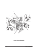
Overdrive Assembly and Drive Roller (Only
Applicable to HP DesignJets 2500CP and 2000CP)
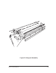
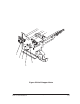
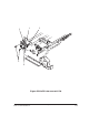
Refer to figure 25A page 8-71
Switch off the printer and remove the power cord.
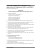
1. Remove the following:
1. Window and Top Cover page 8-15.
2. Left Hand Cover page 8-18.
3. Right Hand Cover page 8-21.
4. Bail Arm Assembly page 8-58
5. Cutter Assembly page 8-48
2. Manually slide the carriage assembly to the right side of the printer.
3. Remove the top half of the elevator assembly by releasing it from two
retaining clips at the back, then lifting up and to the left.
4. Remove the two T-15 screws (item 1) securing the roller support bracket
(item 2) to the left hand side chassis.
5. Remove the roller support bracket.
6. Remove the clutch (item 4) and washers (item 5) on the left end of the
overdrive shaft by removing the retaining clip (item 3).
7. Remove the two T-10 screws (item 8) securing the overdrive assembly
(item 9) to the left and right hand side chassis.
8. Remove overdrive assembly by lifting it out on the right, then sliding to
the right.
To remove the Drive Roller only
9. Remove the following:
1. X-Axis Motor Assembly page 8-45.
2. Service Station Assembly page 8-26.
10.Remove the shoulder screw (item 6) securing the cluster gear (item 7) to
the left hand side chassis.
11.Move the pinch-arm lever to the up position.
12.Remove the drive roller (item 10) by holding the ends and lifting out.