
user manual


8-72 Removal and Installation
HP DesignJet CP Series Printers
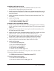
Overdrive Assembly and Drive Roller (Only
Applicable to HP DesignJets 3500CP and 3000CP)
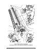
Refer to figure 25B page 8-75
Switch off the printer and remove the power cord.
1. Remove the following:
1. Window and Top Cover page 8-15.
2. Left Hand Cover page 8-18.
3. Right Hand Cover page 8-21.
4. Bail Arm Assembly page 8-58.
5. Cutter Assembly page 8-50.
2. Manually slide the carriage assembly to the right side of the printer.
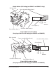
3. Remove the top half of the elevator assembly by releasing it from two
retaining clips at the back, then lifting up and to the left.
4. Remove the two T-15 screws (item 1) securing the roller support bracket
(item 2) to the left hand side chassis.
5. Remove the roller support bracket (item 2).
6. Remove the clutch (item 4) and washers (item 5) on the left end of the
overdrive shaft by removing the retaining clip (item 3).
7. Remove the four T-10 screws (item 8) (two on each side) securing the
overdrive assembly (item 9) to the left and right hand side chassis.
8. Remove the two screws (item 10) (one on each side) securing the
overdrive assembly (item 9) to the left and right hand side chassis.
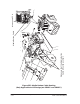
Make sure you disconnect the Media Button Cable from the
Service Station Interconnect PCA (See Figure 25C page 8-76).
9. Remove the overdrive assembly (item 9) by lifting it out on the right,
then sliding to the right.
To remove the Drive Roller only
1. Remove the following:
1. X-Axis Motor Assembly page 8-45.
2. Service Station Assembly page 8-26.