HP 2500C Series Printer Service and Support Manual
Version History Version 2.0 January 1, 1999 Notice The information contained in this document is subject to change without notice. Hewlett-Packard makes no warranty of any kind with regard to this material, including, but not limited to, the implied warranties of merchantability and fitness for a particular purpose. Hewlett-Packard shall not be liable for errors contained herein or for incidental or consequential damages in connection with the furnishing, performance or use of this material.
Contents Chapter 1 Production Information Technology Update......................................................... ............... 1-1 Modular Ink Delivery System ................................... ............... 1-1 Specifications ................................................................................. 1-4 Data Sheet ................................................................................ 1-4 Cable Specifications..................................................................
Chapter 2 Operating Overview Using the Control Panel ................................................................... 2-1 Control Panel Layout ................................................................. 2-1 Indicator Lights.......................................................................... 2-3 Settings and Defaults ................................................................. 2-4 Restoring Factory Defaults......................................................... 2-7 Control Panel Menus..
Chapter 3 Loading Paper and Paper Behavior Loading the Trays ............................................................................ 3-1 Loading Commonly-Used Media in Tray 2 ...................................... 3-2 Loading Commonly Used Media in Tray 3 ...................................... 3-4 Loading Paper in Tray1.................................................................... 3-6 Loading Paper through the Rear Manual Feed.................................. 3-7 Paper Behavior .................
Chapter 5 Maintenance and Ink Cartridge Safety Cleaning the Printer and Accessories ............................................... 5-1 Cleaning Spilled Ink ..................................................................... 5-1 Printhead ...................................................................................... 5-2 Ink Cartridge Safety......................................................................... 5-3 For HP No.10 Color/Black Ink Cartridges.....................................
Chapter 7 Removal and Replacement of Parts (without Calibration) Introduction ..................................................................................... 7-1 Removal and Replacement Tools .................................................. 7-1 Before You Begin ......................................................................... 7-2 Important Notes about Printer Components and Disassembly........ 7-3 Replacement of Parts .......................................................................
Chapter 8 Troubleshooting Troubleshooting Concepts ............................................................... 8-1 LED.............................................................................................. 8-2 Standard Procedures ..................................................................... 8-3 No Power...................................................................................... 8-4 LED or LCD.................................................................................
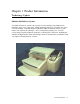
Chapter 1 Product Information Technology Update Modular Ink Delivery System A modular ink delivery system is the separation of ink cartridges and printheads into individual, single-color components. Traditional inkjet printers use one black and one tricolor ink cartridge, each with integrated printheads. HP's modular ink delivery system features four separate ink cartridges--one for each primary printing color--and four corresponding long-life printheads, with tubes connecting the components.
Technology Update How It Works By separating the ink cartridge from the printheads, a modular ink delivery system allows the ink supply to remain in a permanent, fixed position. The printheads remain attached to the carriage and move back and forth, delivering ink to the page as the paper advances through the printer.
Technology Update The Benefits Cuts up to 30 percent off the printing costs of other methods § Modular design means only the component that is no longer useful is replaced. § Longer-life printheads and higher-capacity ink cartridges means less frequent replacement. Achieves color laser speed in a personal desktop printer § Printheads have 304 nozzles apiece (1,216 total, the most in the industry) resulting in faster print speeds.
Specifications Data Sheet Print Method Print Speed 1 Black Plain paper drop on-demand thermal inkjet printing. Black Text Letter / A4 11x17 / A3 Econofast Mode 9 ppm 5 ppm Normal Mode 7 ppm 3 ppm Best Mode 7 ppm 3 ppm Print Speed 1 Color Color Highlights Econofast Mode Normal Mode Best Mode Letter / A4 9 ppm 6 ppm 5 ppm 11x17 / A3 5 ppm 3 ppm 2 ppm Mixed Text & Graphics Econofast Mode Normal Mode Best Mode Letter / A4 7 ppm 3.5 ppm 1.2 ppm 11x17 / A3 4 ppm 2 ppm 0.
Connectivity /Network Management HP2500C Network-capable printer for DOS and Windows environments Enhanced HP PCL 3e Windows Driver Support for Windows NT 4.0, Windows 3.
Paper Size Handling Maximum Print Width Recommended Media Weight Minimum Width: 76.2 mm (4in.) x 127.0 mm (6 in.) Maximum Width: 330.2 mm (13in.) x 482.6 mm (19 in.) 320 mm (12.61 in.) x 470 mm (18.49 in.) on 13 in. x 19 in. media All input paths handle the following paper weights with the rear straight-through paper path handling up to 0.3 mm thickness of paper Paper / Labels: 60 to 135 g/m2 (16 to 36 lb. Bond) Cards: 110 to 200 g/m2 (110 lb. Index) Straight-through path: up to 0.3 mm thickness (0.012 in.
Dimensions With paper tray closed 685 mm (26.97in.) W x 610 mm (24.02in.) D x 337 mm (13.27in.) H With paper tray fully extended 685 mm (26.97in.) W x 745 mm (29.33in.) D x 337 mm (13.27in.) H Desk Space Required 685 mm (26.97 in.) W x 532 mm (20.94 in.) D Weight Reliability & Estimated Usage System Requirements 26.5 kg (58.48 lb.) without printheads and ink cartridges 27.0 kg (59.52 lb.) with printheads and ink cartridges Up to 12,000 pages / month Minimum: Windows 3.
Specifications Cable Specifications 1284-B Connector Pin Assignments The pin numbers and their assigned signal names for the 1284-B connectors are given below.
30 Signal Ground (nAutoFd, nSelectIn, nInit) 31 H nInit nInit nInit nReverseRequest nInit 32 P nFault nDataAvail nDataAvail nPeriphRequest User Defined 2 1284 Active nAStrb 33 Not Defined 34 Not Defined 35 Not Defined 36 H nSelectIn 1284 Active 1284 Active ∗ Data signals will be driven by some but not all peripheral devices. ∗ Pins not defined by this spec are used by manufacturers at their own risk.
Specifications Centronics Parallel Pinout Information PIN NUMBER 1 PIN ID 1 DESCRIPTION 1 Strobe 2-9 Data 0 - Date 7 These pins are the data lines. Data 0 is the least significant bit (LSB) 10 Acknowledge The printer sends a low pulse to indicate that it has accepted a byte of data and is ready for more data. 11 Busy The printer sends a high logic level to indicate to the computer that it cannot receive data due to data entry, a full buffer or error status.
Specifications The Centronics Parallel Cable has only 8 data lines, 5 status lines, 4 ground lines and ground connections between the host PC and the peripheral. Each of the signal lines has a corresponding bit position in a memory address (register) in the host where data is read or written.
Specifications IEEE 1284 Pinout Information Any standard IEEE 1284 compliant printer cable will work with the printer. The customer can order the HP IEEE 124 Compliant Parallel Interface Cable C2950A (2 meters) or C2951A (3 meters). See Ordering Parts in Chapter 12 for ordering information. PIN NUMBER PIN ID DESCRIPTION 1 HostClk Used in a closed-loop handshake with PeriphAck to transfer data or address information from the host to the peripheral device.
32 nPeriphRequest During ECP mode the peripheral may drive this pin low to request communications with the host. This request merely “hints” to the host; the host has ultimate control over the transfer direction. This signal provides a mechanism for peer-to-peer communication. This signal is valid in the forward and reverse directions. 36 1284 Active Driven high by host while in ECP mode.
Specifications Reliability Specifications Category Printer Usage Specifications Up to 12,000 pages / month Mechanism Life 150,000 A size pages / 5 years 1-14 Product Information
Specifications Interface Specifications Category Interface Specification Specifications § Centronics parallel, IEEE 1284 Compliant with 1284-B receptacle (ECP) § 64KB buffer size Product Information 1-15
Specifications Physical Dimensions With paper tray closed (W x D x H) With paper tray fully extended (W x D x H) Weight Desk space needed (W x D) 27.0 x 24.0 x 13.3 inches 685 x 610 x 337 mm 27.0 x 29.3 x 13.3 inches 685 x 745 x 337 mm 26.5 kg (58.48 lb.) without printheads and ink cartridges 27.0 kg (59.52 lb.) with printheads and ink cartridges 27.0 x 21.
Specifications Packaging Dimensions Specifications 792 mm (31.3 in.) W x 731 mm (28.8 in.) D x 457 mm (18.0 in.
Specifications Electrical Specifications Category Input Voltage Frequency Interface Specification Specification 100 to 240 Vac (±10%) 50/60 Hz (±3 Hz) Centronics parallel, IEEE 1284 Compliant with 1284-B receptacle (ECP) Power Consumption § Idle § Printing 4.4 watts 35 watts max. Transient Spike Immunity § Amplitude 1 kV § Pulse width 50 µseconds § Rise time 1.
Specifications Environmental Specifications Category Specifications Temperature § Operating § Storage condition § Recommended operating 5 °C to 40 °C (41 °F to 104 °F) -40 °C to 60 °C (-40 °F to 140 °F) 15 °C to 35 °C (59 °F to 95 °F) Humidity § Operating § Storage condition § Recommended operating 10%-80% RH non-condensing 10%-80% RH non-condensing 20%-80% RH non-condensing Altitude § Operating § Non-operating 0 to 3100 meters 0 to 4600 meters Mechanical Vibration § Frequency range § Operating (Ran
Specifications Product Certifications Safety Certifications EMI Certifications CCIB (China) C TICK (Australia and New Zealand) CSA (Canada) VCCI (Japan) NOM1 (Mexico) CE (European Union) PSB (Singapore) GOST (Russia) TUV-GS (Germany) B mark (Poland) UL (USA) GOST (Russia) SABS (South Africa) BCIQ (Taiwan) JUN (Korea) RRL (Korea) EMI FCC Class B when used with a Class B computing device (USA) 1-20 Product Information
Specifications Media Sizes Supported The following are the media sizes supported by the printer. General type Sizes (mm) Sizes (inch) Remarks Tray 1 (Input / Output Tray) Post Card 100x148 3.94x5.83 Minimum Size Including all media sizes in Tray 2 (Upper Tray) / Tray 3 (Lower Tray) Tray 2 (Upper Tray) / Tray 3 (Lower Tray) ISO-A4 210x297 8.27x11.7 US-Letter 215.9x279.4 8.5x11 US-Legal 215.9x355.6 8.5x14 JIS-B4 257x364 10.11x14.33 US-B (Ledger) 279.4x431.8 11x17 ISO-A3 297x420 11.69x16.53 Super B 330.
Specifications Recommended Media Weight Paper 60 to 135 g/m2 (16 to 36 lb. Bond) Cardstock 110 to 200 g/m2 (110 lb. Index) (up to 0.012 in. or 0.
Specifications Paper Handling Media Type Capacity (Pages) Tray 1 (Input / Output Tray) Sheets 10 Cards 4 Tray 2 (Upper Tray) Sheets 150 Cards 60 Tray 2 (Upper Tray) Sheets 250 Rear Manual Feed All media sizes from 4x6 inches (101.6x152.4mm) to 13x19 inches (330.2x482.6mm) and maximum thickness of 0.3mm (0.012 inches) Output Tray Sheets (face-up) 1 150 Note 1. There is a sensor mounted on the bypass paper feed to indicate whether it is in use.
Specifications Printable Area Printable area (Portrait orientation) Printable area (Landscape orientation) The table as follows will show the minimum margin of each media type (portrait orientation) for the HP 2500C Series Printer. Please note that the printable area is smaller than that of HP LaserJets.
Specifications Media Margins (in portrait orientation) Media Type US Letter 8.5 x 11 in. 215.9 x 279.4 mm Tabloid / Ledger 11 x 17 in. 279.4 x 431.8 mm A4 8.27 x 11.69 in. 210.00 x 296.9 mm A3 11.69 x 16.53 in. 296.9 x 419.9 mm B4 10.12 x 14.33 in. 257.0 x 364.0 mm Legal 8.5 x 14 in. 215.9 x 355.6 mm Executive 7.25 x 10.50 in. 184.2 x 266.7 mm A5 5.83 x 8.27 in. 148.0 x 210.0 mm B5 7.16 x 10.12 in. 181.9 x 257.0 mm 4x6 Index Card 4.00 x 6.00 101.6 x 152.4 5x8 Index Card 5.00 x 8.00 127.0 x 203.
A6 Card 4.13 x 5.83 105.0 x 148.0 Hagaki Card 3.94 x 5.83 100.0 x 148.0 Super B 13.00 x 19.00 330.2 x 482.6 Statement 5.50 x 8.50 139.7 x 215.9 C Size 17.00 x 22.00 431.8 x 558.8 A2 16.53 x 23.38 419.9 x 593.9 Hagaki 7.87 x 5.83 200.0 x 148.0 A3 Nobi 13.00 x 19.00 330.2 x 482.6 Custom 3.94 to 13.00 x 5.83 to 19.00 100 to 330 x 148 to 482 0.12 in. 3.1 mm. 0.12 in. 3.1 mm. 0.12 in. 3.0 mm. 0.50 in. 12.7 mm. 0.12 in. 3.1 mm. 0.12 in. 3.1 mm. 0.12 in. 3.0 mm. 0.50 in. 12.7 mm. 0.20 in. 5.1 mm. 0.
Specifications Hewlett-Packard Ink Cartridge Specifications Category Type Printhead Nozzles Black Resolution Color Resolution Ink Drop Volume Print Speed1 Black Specification Plain paper drop on-demand thermal inkjet printing 304 black, 912 color (304 per color printhead) Up to 600x600 dpi PhotoREt II for photo quality 35ng black, 8ng color drop volume for high resolution printing Black Text Letter / A4 11x17 / A3 Econofast Mode 9 ppm 5 ppm Normal Mode 7 ppm 3 ppm Best Mode 7 ppm 3 ppm Print Speed1 Color
Specifications System Requirement The following CPUs and memory are required : Minimum: Windows 3.1x: 486DX-66, 8 Mb RAM Windows 95/98: 486DX-100, 8 Mb RAM Windows NT 4.0/5.0: 486DX-66, 16 Mb RAM Macintosh System 7.5.3 or later: 68040 – 8 Mb RAM Recommended: Windows 3.1x: Pentium 150/166, 16 Mb RAM Windows 95/98: Pentium 150/166, 16 Mb RAM Windows NT 4.0/5.0: Pentium 150/166, 32 Mb RAM Macintosh System 8 or later: Power PC – 16 Mb RAM 50 Mb free hard disk space for 11x17 or A3 size printing.
Product Overview Printer External View Model and Serial Number The serial number of the HP 2500C Series Printers can be found on the labels at the back of each printer and at the top of the main case (concealed by the top cover). The figure below shows how the serial number is interpreted. Serial Number = CCYMDVL### CC (Country) Y (Year) M (Month) D (Day) V (Version) L (Line) ### The country show where the printer was manufactured. The year the printer was manufactured.
Supplies and Accessories Product Structure The following items will be shipped in the box: Basics Printer Extended Tray Cover (a) Driver Kit Starter CD (b) HP JetDirect CD (HP 2500CM printer only)(b) User’s Guide (d) Hardcopy Kit Setup Poster (c) Getting Started Guide (Not available in U.S.) Quick Reference Guide (e) User’s Guide (Available in U.S. only) Accessory Kit Power Cord (f) Four HP No. 10 Ink Cartridges (h) (Black, Cyan, Magenta and Yellow) Four HP No.
Supplies and Accessories Power Cord US Europe 8120-6805 8120-6802 Australia Singapore / Malaysia SA UK 8120-6803 8120-6809 8120-6808 8120-6801 #ABB, #ABM, #AC4, #AKY, #A2L, #ABA #ABS, #AKB, #ACB, #ABT, #AKC, #ACT, #AB7, #ABB, #ARG, #ARP, #AKY #ABG, #AKY #AB4 #ACQ #ABU Product Information 1-31
Supplies and Accessories Network Interface The following cards have been tested with the HP 2500C and HP 2500CM Color Printer.
Supplies and Accessories Print Cartridge No. 10 Cyan Ink Cartridge No. 10 Magenta Ink Cartridge No. 10 Yellow Ink Cartridge No. 10 Hi Capacity Black Ink Cartridge No. 10 Cyan Pen No. 10 Magenta Pen No. 10 Yellow Pen No. 10 Black Pen C4841A C4842A C4843A C4844A C4801A C4802A C4803A C4800A Note The HP 2500C/CM Printers are shipped with a Low Capacity Black Ink Cartridge (C4840A).
Supplies and Accessories Media HP Bright White Paper (500 / A size) HP Bright White Paper (500 / A4 size) HP Bright White Paper (200 / 11x17 size) HP Bright White Paper (200 / A3 size) HP Premium InkJet Coated Paper (200 / A) HP Premium InkJet Coated Paper (200 / A4) HP Premium InkJet Coated Paper (100 / 11x17) HP Premium InkJet Coated Paper (100 / A3) HP Premium InkJet Heavyweight Paper (100 / A) HP Premium InkJet Heavyweight Paper (100 / A4) HP Premium Photo Paper (20 / 11x17) HP Premium Photo Paper (20 /
Supplies and Accessories Other Accessories HP 64MB (2x32MB) 60ns EDO SIMM HP 32MB (2x16MB) 60ns EDO SIMM HP 16MB (2x8MB) 60ns EDO SIMM HP 2500C Postscript 3 Upgrade Kit D4543A D3648B D3647B C3289A Customer Replaceable Parts Note The following parts are customer replaceable parts. Replacing these parts require no technical expertise. These parts can be sent directly to the customer by the Customer Care Centers after qualification.
Warranty and Support The warranty for HP 2500C Series Printers varies depending on the product, the date and the country of purchase. For products returned under warranty, Hewlett-Packard may : § Provide on-site repair, § Replace the product with a remanufactured unit, § Replace the product with a product of equal or greater functionality or § Refund the purchased price.
Warranty and Support Hewlett-Packard Limited Warranty Statement HP Product Software Print Cartridges Printer Printheads Duration of Limited Warranty 1 year 90 days 1 year 1 year Extent of Limited Warranty 1. Hewlett-Packard (HP) warrants to the end user customer that HP products will be free from defects in materials and workmanship, for a specified time after the date of purchase by the customer. The duration of this limited warranty is stated above.
5. If HP receives, during the applicable warranty period, notice of a defect in a hardware product which is covered by HP’s warranty, HP shall either repair or replace the product, at its option. Any replacement product may be either new or like-new, provided that it has functionality at least equal to that of the product being replaced. 6.
Limitations of Liability 1. EXCEPT FOR THE OBLIGATIONS SPECIFICALLY SET FORTH IN THIS WARRANTY STATEMENT, IN NO EVENT SHALL HP BE LIABLE FOR ANY DIRECT, INCIRECT, SPECIAL, INCIDENTAL, OR CONSEQUENTIAL DAMAGES, WHETHER BASED ON CONTRACT, TORT, OR ANY OTHER LEGAL THEORY AND WHETHER ADVISED OF THE POSSIBILITY OF SUCH DAMAGES.
Warranty and Support Obtaining Printer Drivers The HP 2500C Series Printer Driver Software is updated periodically. The latest versions can be obtained from authorized Hewlett-Packard dealers or any of the sources listed below. 24-hour Modem Access Internet HP 2500C Series Printer drivers and product support information can be obtained through the World Wide Web at: http://www.hp.
Warranty and Support Service Support Contracts In the U.S. HP SupportPack The HP SupportPack is an enhancement to the customer’s original one-year warranty repair service. The HP SupportPack provides next business day on-site support for the duration of an additional two years of warranty. This service enhancement provides customers with a cost-effective and timely way to achieve quality support.
Warranty and Support Service and Support Resources Hewlett-Packard News Network (HPNN) HPNN is an electronic bulletin board service available only to HP authorized resellers. This service provides the following information: § § § § § Presales Information Printer Drivers HP SupportPack Information Software Notes Postsales Information For more information, call 1 (408) 553-7303. HP Customer Information Center The HP Customer Information Center provides presales product information.
Warranty and Support HP BBS Library The HP electronic bulletin board library service, which is available 24 hours a day, 7 days a week, contains drivers and support information which can be downloaded to your PC via modem.
Warranty and Support HP FAXback on Demand – HP FIRST You can use this service to select documents, such as product descriptions and technical information. To access this service, use the handset on your fax machine and dial the appropriate number from the table in this section. Use the following steps to use HP FIRST: 1. Call the system. You will need to use a touch-tone telephone or the phone set of your fax machine. A voice prompt will welcome you and guide you to the information you need.
Warranty and Support HP FIRST Telephone Numbers Country For US and Canada Telephone Number (800) 333-1917 For Customers in Europe: U.K. For service in English outside U.K.
Warranty and Support HP Telephone Support Technical Phone Support for Customers The HP Customer Support Center provides free technical assistance for peripherals within the hardware warranty period. For the product under warranty, call (208) 323-2551. For the product out of warranty, call : § 1 (900) 555-1500 at $2.50 per minute, or § 1 (800) 999-1148 at $25.00 per call using VISA / MasterCard.
Warranty and Support Warranty and Out-of-Warranty Support Telephone Numbers Country (Language) Austria (German) Belgium (Dutch) Belgium (French) Denmark (Danish) Finland (Finnish) France (French) Ireland Germany (German) Italy (Italian) Netherlands (Dutch) Norway (Norwegian) Portugal Spain (Spanish) Sweden (Swedish) Switzerland (French) Switzerland (German) UK English language support for other European countries Telephone Number 0660-6386 02 626 8806 02 626 8807 3929 4099 0203 47288 04 50 43 9853 01 622 5
Warranty and Support Contacting Hewlett-Packard To contact HP, check your local telephone directory for the HP Sales and Service Office near you. If you cannot find an HP office, contact one of the major HP Sales and Service Offices or one of the following Worldwide Marketing Headquarters. Asia Far East Sales Region Headquarters Hewlett-Packard Asia Ltd. 22/F Peregrine Tower Lippo Centre 89 Queensway, Central Hong Kong Canada Hewlett-Packard Ltd.
Warranty and Support Worldwide Customer Support Numbers Customer Support Centers provide technical information via telephone directly with online agents who are trained to assist with setup, configuration, startup and troubleshooting of HP products. Customer Support Center assistance can be obtained by calling one of the following country-specific telephone numbers: Note Check the world wide web at http://www.hp.com/go/hp2500 for the most up-to-date customer support telephone numbers.
For Europe Africa/Middle East Austria Belgium (Dutch) Belgium (French) Czech Republic Denmark Finland France Germany Greece Hungary Ireland Italy Norway Poland Portugal Russia Spain Sweden Switzerland Netherlands Turkey United Kingdom 41 22/780 71 11 0660 6386 02 6268806 02 6268807 42 (2) 471 7327 3929 4099 203 47288 01 43 62 34 34 180 5258 143 0168 96 411 36 (1) 252 4505 01662 5525 02 264 10350 22 11 6299 48 22 37 50 65 01 441 7199 7095 923 50 01 902 321 123 08 619 2170 0848 80 11 11 020 606 8751 90 1 224
Chapter 2 Operating Overview Using the Control Panel The Control Panel allows you to perform most major tasks with the printer, including controlling print status, resetting from recoverable errors and changing the printer's default settings.
Using the Control Panel The functions of each of the buttons are as follows : Control Panel Key [ GO ] [ Cancel Job ] [ Menu ] [ Item ] [ Value ] [ Select ] 2-2 Operating Overview Function Puts the printer either online or offline. Allows the printer to resume printing after going offline. Also clears most printer messages and puts the printer online. § Allows the printer to continue printing after a noncritical warning message such as UNEXPECTED PAPER SIZE or TRAY x LOAD [ TYPE ] [ SIZE ].
Using the Control Panel Indicator Lights There are two LEDs (lights) on the printer : LED Indicators Ready LED Color Green Attention LED Red Error LED Green + Red blinking rapidly Function Lit up when the printer is printing OR in normal state OR when it is online. Blinks when the printer is in an error state OR requires attention. Both LEDs blink when the printer detects an error. Power cycle the printer to correct. If the error persists, push the on-line button once to see the error message.
Using the Control Panel Settings and Defaults These are the various possible menu settings. The factory defaults, where applicable, are indicated in bold. Other additional menu items may also appear, depending on which hardware modules have been installed in the printer. For more information on these settings, refer to Control Panel Menus (Chapter 2).
Self Test Menu PRINT MENU MAP PRINT PS FONT LIST (Available if PS installed) PRINT MARKETING DEMO (Available if Demo DIMM installed) PRINT DIAGNOSTIC PAGE PERFORM TRAY2 PAPER PATH TEST PERFORM TRAY3 PAPER PATH TEST PERFORM TRAY1 PAPER PATH TEST Print Quality Menu PRINT QUALITY = NORMAL ECONOFAST BEST Printing Menu PAPER = ORIENTATION = APPEND CR TO LF = LETTER LEGAL 13X19 A4 A3 11X17 JISB4 PORTRAIT LANDSCAPE NO YES I/O Menu IN JOB TIMEOUT = OUT JOB TIMEOUT = I/O CHANNEL TIMEOUT = 45 (5 - 300 secs) 0
Configuration Menu AUTO PCL PS (Available if PS installed) PERSONALITY = MIO Menu (Available if DIMM installed) (Available if MIO installed) CONFIGURE MIO (The remaining options will appear depending on the type of MIO card installed.
Using the Control Panel Restoring Factory Defaults To restore the default factory settings, press [ MENU ] till the Resets Menu appears. Then press [ ITEM ] until RESET TO FACTORY SETTINGS is shown in the LCD display. Press [ SELECT ] to restore the factory defaults. This action will also clear the input buffer for the active I/O channel.
Using the Control Panel Control Panel Menus The following is a summary diagram of all the menus available in the HP 2500C series printer : 2-8 Operating Overview
Using the Control Panel Paper Handling Menu Item Value TRAY 2 TYPE=PLAIN PLAIN HP INKJET/HEAVY HP PHOTO TRNSPRNCY/IRON RAPID TRNSPRNCY Explanation Set this value to correspond with the paper type currently loaded in Tray 2. PLAIN: Plain paper HP INKJET/HEAVY: HP Premium Inkjet Paper or HP Premium Inkjet Heavyweight Paper HP PHOTO: HP Premium Photo Paper TRNSPRNCY/IRON: HP Premium Transparency Film or HP Iron-on T-Shirt Transfer RAPID TRNSPRNCY: HP Premium Inkjet Rapid-Dry Transparencies.
Transparency Film or HP Iron-on T-Shirt Transfer RAPID TRNSPRNCY: HP Premium Inkjet Rapid-Dry Transparencies.
Using the Control Panel Diagnostics Menu Item ALIGN PRNT-HDS CLEAN PRNT-HD: LEVEL 1 CLEAN PRNT-HD: LEVEL 2 CLEAN PRNT-HD: LEVEL 3 PERFORM TRAY 2 PAPER PATH TEST PERFORM TRAY 3 PAPER PATH TEST PERFORM TRAY 1 PAPER PATH TEST Explanation This item aligns the printheads to ensure printout of the best possible print quality. This item cleans the printheads. Level 1 is the basic level and should be performed first. This option will cause the printer to perform a dry wipe and spitting.
Using the Control Panel Information Menu Item CHECK INK LEVEL Explanation This item displays the amount of ink remaining in each ink cartridge. The following screen appears on the LCD: B C M Y 60% 80% 80% 80% BASE FW VER B, C, M and Y represent the black, cyan, magenta and yellow cartridges respectively. The corresponding percentage under each letter indicates the amount of ink left (from 0% to 99%). This item displays the firmware version of the printer. Example: VERSION=5.
Using the Control Panel Self-Test Menu Item PRINT MENU MAP PRINT PS FONT LIST PRINT DIAGNOSTIC PAGE PRINT EXT DIAGNOSTIC PAGE Explanation The Menu Map shows the layout of the Control Panel menu items. The PS Font List shows all the PS fonts currently available to the printer. This option is activated only if PS Personality module has been installed. The Diagnostic Page shows general printer information and current network parameters. See Diagnostic Page (Chapter 2).
Using the Control Panel Print Quality Menu Item Value PRINT QUALITY= NORMAL NORMAL ECONOFAST BEST Explanation NORMAL: Normal mode delivers high quality output and is the recommended setting for speed and quality. Normal mode is the default setting for most paper types. ECONOFAST: Draft quality printing. EconoFast mode prints faster than Normal mode and delivers comparable output. Using EconoFast will also cut down on the frequency of replacing your ink cartridges because it uses less ink.
Using the Control Panel Printing Menu Item Value PAPER= LETTER LETTER LEGAL 13X19 A4 A3 11X17 JISB4 PORTRAIT LANDSCAPE ORIENTATION= PORTRAIT APPEND CR TO LF= NO NO YES Explanation Sets the paper size. Determine the default orientation of print on the page. Note: It is best to set the page orientation from the printer driver or software application. Select YES to append a carriage return to each line feed (LF) encountered in backward-compatible PCL jobs (pure text, no job control).
Using the Control Panel I/O Menu Item IN JOB TIMEOUT= 15 Value 5 to 300 Explanation Selects the amount of time (in seconds) that the printer will wait within a print job before ending it. When the data from a print job is not completely sent to the printer, the printer will wait for this specified number of seconds. After that, it will abort the job and carry on to process the next print job.
Using the Control Panel Resets Menu Item RESET TO FACTORY SETTINGS RESET ACTIVE I/O CHANNEL RESET ALL I/O CHANNELS RESET MIO TO FACTORY SETTINGS Explanation This item performs a simple reset and restores most of the factory (default) settings. This item also clears the input buffer for the active I/O. This item performs a simple reset and clears the input and output buffers (for the active I/O channels only). This item performs a simple reset and clears the input and output buffers for all I/O channels.
Using the Control Panel MIO Menu This menu is available only if the MIO card is installed. It is controlled by the MIO print server which has been installed on the printer and thus varies accordingly. Please refer to the documentation that comes with the print server for more information.
Using the Control Panel Aligning Printheads To align the printheads from the LCD : 1. 2. 3. 4. 5. 6. Press the [ Menu ] button until “Diagnostic Menu”. Press the [ Item ] button until “Align Printheads”. Press the [ Select ] button. LCD message “Printing Pattern Page”. Printer prints alignment page with horizontal and vertical alignment patterns. The following screen appears on the LCD: A 3 B 3 C 3 D 3 E 3 7. The value “3” at A is flashing. 8.
Note 1. The printer has only one data-line to check for shorts. It is possible that the original error message will refer to a different print head as the one that is actually having the ink short. The Ink Head Diagnostic Process will help you identify the print head having the problem. 2. Not all cases of ink shorts can be diagnosed by the Printhead Diagnostic Process. If the diagnostic program is not able to diagnose correctly, replace the printheads one after another to identify the faulty printhead.
Error Codes Recoverable Error Codes A recoverable error is one that is defined as an anomaly that will cause the printer to pause until the user resolves the error. The other two types of errors are: warning errors, which will highlight a potential problem to the user but does not cause the printer to stop operation, and unrecoverable errors, which are generally irresolvable by the user and will cause the printer to stop functioning altogether.
TRAY [NUMBER] EMPTY, LOAD & PRESS PRESS TO CONTINUE MEDIA IN TRAY 1, REMOVE The specified tray is empty. To continue your present task, press the button. There is media in Tray 1 which may not be the type or size that is specified in your current print job. WRONG MEDIA TYPE, [ACTION] The media type which the printer has detected is not the type specified in your print settings. UNEXPECTED PAPER SIZE The specified paper size is different from the paper size in the selected input tray.
Error Codes Unrecoverable Error Codes Display error code on LCD: “ERROR CODE: XXXX-XXXX” The unrecoverable error codes are coded and refer to the printer module that is experiencing a failure. Some of the codes in the list below have a comment “Not Used”. These codes are only for development purposes and should no longer be triggered by the firmware.
131 132 133 134 INK_LEAK_ERR_K INK_LEAK_ERR_C INK_LEAK_ERR_M INK_LEAK_ERR_Y 2-24 Operating Overview (Development error) ISS error – Not used ISS error – Not used ISS error – Not used ISS error – Not used Pump detected OOI before level down. Pump detected OOI before level down. Pump detected OOI before level down. Pump detected OOI before level down.
139 141 142 143 144 145 146 147 148 149 151 152 153 154 155 156 157 158 159 161 162 163 164 165 166 DEFERRED_ERROR_TRAP NVM_ERR_NOT_INIT NVM_ERR_GENERIC NVM_ERR_DEVICE_ABSENT NVM_ERR_WRITE NVM_ERR_READ NVM_ERR_READBACK NVM_ERR_DATA_NOT_VALID NVM_ERR_UNKNOWN_TAG NVM_ERR_UNKNOWN_FORMAT NVM_ERR_BAD_CHIP_TAG NVM_ERR_BAD_FAMILY NVM_ERR_BAD_COLOR NVM_ERR_TSR_VALUE NVM_ERR_DROP_VALUE NVM_ERR_BAD_TOKEN NVM_ERR_BAD_WRITE_PROT NVM_ERR_BAD_MODEL_NUM NVM_ERR_INCOMPAT_INK NVM_ERR_BAD_MFG_WEEK NVM_ERR_SPARE NVM_ERR_POOL
181 182 183 184 185 186 187 188 189 Critical Task WatchDog Timeouts CRIT_TASK_WD_TASK_1 CRIT_TASK_WD_TASK_2 CRIT_TASK_WD_TASK_3 CRIT_TASK_WD_TASK_4 CRIT_TASK_WD_TASK_5 CRIT_TASK_WD_TASK_6 CRIT_TASK_WD_TASK_7 CRIT_TASK_WD_TASK_8 CRIT_TASK_WD_TASK_9 211 221 222 223 224 225 226 227 228 229 Pens and Darwin Errors SB_ERR_FORCE_RESET SB_ERR_BAD_XFER_CMD SB_ERR_NO_SLAVE_ADDR SB_ERR_MISSING_ACK SB_ERR_HARDWARE_FAULT SB_ERR_UNEX_STOP_BIT SB_ERR_UNEX_START_BIT SB_ERR_DATA_ERROR SB_ERR_MISSING_STOP SB_ERR_MISSING_S
325 326 327 328 329 331 332 333 334 335 336 337 338 339 341 342 343 344 345 346 347 348 349 351 352 353 354 355 356 357 358 359 361 362 363 RED_DM_ERR_INVALID_HDR RED_DM_ERR_DELETE_FONT RED_DM_ERR_MODIFY_FONT RED_DM_FONT_SELECTMODE_ERROR RED_DM_FONT_FORMAT_ERROR RED_DM_FONT_WEIGHT_ERROR RED_DM_FMTR_INVALID_CHANNEL RED_DM_FMTR_CANNOT_SUBMIT_INPUT RED_DM_FMTR_CANNOT_ALLOC_MEM RED_DM_PCL_ERROR RED_DM_PCL_INVALID_ORIENTATION RED_DM_PCL_INVALID_POSITION RED_DM_PCL_INVALID_CHARACTER RED_DM_PCL_UNDERLINE_ERROR RE
397 398 399 I/O problems –firmware problem => reset printer or PCA replacement I/O problems –firmware problem => reset printer or PCA RED_DM_IO_UNSUPPORTED_SOCKET replacement I/O problems –firmware problem => reset printer or PCA RED_DM_MLC_CREDIT_GONE_BAD replacement I/O problems –firmware problem => reset printer or PCA RED_DM_MLC_CREDIT_GONE_BAD2 replacement I/O problems –firmware problem => reset printer or PCA RED_DM_MLC_INSUFFICIENT_MEM replacement I/O problems –firmware problem => reset printer or P
421 422 423 424 425 426 427 428 429 431 432 433 434 435 436 437 MECH_BAD_BLACK_PEN MECH_BAD_CYAN_PEN MECH_BAD_MAGENTA_PEN MECH_BAD_YELLOW_PEN MECH_BLACK_OOI MECH_CYAN_OOI MECH_MAGENTA_OOI MECH_YELLOW_OOI MECH_UDV_PROB MECH_PEN_E_5_SHORT MECH_SS_FAILURE MECH_NO_RAMP_MEMORY MECH_BAD_SPIT_FREQ MECH_PEN_VP1_SHORT MECH_PEN_VP2_SHORT MECH_PEN_E_12_SHORT 438 MECH_ALL_PENS_BAD 439 MECH_CARRIAGE_LATCH_ERROR 441 442 443 444 445 446 451 452 453 454 455 456 457 458 459 461 462 463 464 MECH_PUMP_JAM MECH_STALLED_
Linefeed motor stall – Linefeed motor/ Linefeed PCA/ encoder wheel/ Logic PCA Linefeed motor stall – Linefeed motor/ Linefeed PCA/ encoder wheel/ Logic PCA 465 MECH PAPERMOTOR STALL 466 MECH PAPERMOTOR SLOW MOVE 511 512 513 514 515 516 517 518 519 521 522 523 549 551 552 553 554 555 556 557 558 559 561 I/O Manager IO_BAD_TIMER P1284_DOUBLE_READ P1284_ISR_INVALID_STATE P1284_BAD_TIMER P1284_ISR_UNRECOGNIZED P1284_BAD_DMA_SIZE P1284_NO_READ P1284_DMA_NOT_OFF P1284_DOUBLE_WRITE P1284_NO_WRITE P1284_CORRU
631 632 633 634 635 636 637 38 641 642 643 651 661 671 672 FLASH_ERR_ERASE_CMD FLASH_ERR_ERASE_FAILED FLASH_ERR_TIME_ES_INIT FLASH_ERR_TIME_SUSPEND FLASH_ERR_TIME_PAGEBUF FLASH_ERR_TIME_QUEUE FLASH_ERR_TIME_CMD FLASH_ERR_VPP_BAD FLASH_ERR_WRITE_START FLASH_ERR_WRITE_FAILED FLASH_ERR_DATA_BAD FLASH_ERR_2MANY_ERASE FLASH_ERR_2MANY_WRITE FLASH_ERR_BUF_DATA_BAD FLASH_ERR_ENCODING Error can only occur when flashing firmware Error can only occur when flashing firmware Error can only occur when flashing firmware
925 926 DM_MESSAGE_SEND_FAILED DM_MESSAGE_RECV_FAILED 971 FMT_SEM_CREATE_ERROR 972 SWI_SEM_TAKE_ERROR Reset printer Reset printer I/O Switcher 2-32 Operating Overview Firmware error managing auto I/O switching – Reset Printer Firmware error managing auto I/O switching – Reset Printer Failed to send message to dmEventMsgQ.
Printer Diagnostic Pages The HP2500C can test-print up to two self-diagnostic pages: the diagnostic page and extended diagnostic page. A PostScript (PS) configuration page may also be printed if the PS Personality Module has been installed. Please note that the default pick for diagnostic pages is determined by the firmware version of the printer and can not be changed. Diagnostic pages will by default always pick from Tray 2 or Tray 3 (depending on firmware rev.).
Printer Diagnostic Pages Printhead Info § § § Pages Printed (approximate): this takes the format B C M Y, and shows how many pages have been printed by each individual printhead. Nozzles Disabled (<3 OK): this shows, if any, the number of printhead nozzles that are not functioning properly. If any of the nozzles are disabled, the problem may be rectified by trying any of the cleaning procedures. Disabled nozzles may also indicate printhead end-of-life.
Printer Diagnostic Pages Extended Diagnostic Page The extended diagnostic page is used by manufacturing to show the NVRAM values for the printheads, cartridges and PCA. PS Configuration Page Available only be printed if the PS Personality Module has been installed. It prints all the PS fonts which are available on the module.
2-36 Operating Overview
Chapter 3 Loading Paper and Paper Behavior Loading the Trays Overview The HP 2500C/CM Printer has 3 paper trays and 1 Rear Manual Feed. Tray 1 - This tray is used as a bypass tray, and holds up to 10 sheets of paper. This tray should be used for media types and sizes that are seldom used. Tray 2 - This tray holds up to 150 sheets of paper. It is recommended that you use this tray to hold commonly-used paper. Tray 3 - This tray holds up to 250 sheets of paper.
Loading Commonly-Used Media in Tray 2 Tray 2 is designed to hold up to 150 sheets of paper, and can accommodate the paper sizes : Letter, A4, Legal, B4, A3, 11"x17", 13"x19" and 330x483mm. 11, 2 1. Remove Tray 1. 2. If you wish to change the paper size setting that has been set for the tray, go to step 3. If you wish to load paper using the existing tray setting, go to step 5. 3 3. Adjust the Paper Length and Paper Width guides to the correct slots.
Loading Commonly-Used Media in Tray 2 5 5. Insert the paper, print side down, into the printer. 6. Tap the left side of the stack of paper to ensure that it is flush with the right side of the tray. 7 7. Replace Tray 1. 8 8. If Tray 2 is extended, place the Extended Tray Cover over the tray. 9. If you are loading a different type of media, press [ Menu ] on the Control Panel until PAPER HANDLING MENU appears. 10. Press [ Item ] to select TRAY 2 TYPE= . 11.
Loading Commonly-Used Media in Tray 3 1 1. Grasp the sides of Tray 3 and pull it out of the printer. 2. If you wish to change the paper size setting that has been set for the tray, go to step 3. If you wish to load paper using the existing tray setting, go to step 5. 3 3. Adjust the Paper Length and Paper Width guides to the correct slots. Respective paper size markings are indicated beside each slot. 4 6 4.
Loading Commonly-Used Media in Tray 3 7 7. If Tray 3 is extended, place the Extended Tray Cover over the tray. 8. If you are loading a different type of media, press [ Menu ] on the Control Panel until PAPER HANDLING MENU appears. 9. Press [ Item ] to select TRAY 3 TYPE= . 10. Press [ Value ] to select the media type you have loaded into the tray and press [ Select ].
Loading Paper in Tray 1 1. Set your driver to pick paper from Tray 1 and print your document (i.e. send the print job to the printer). 2. After sending the print job, the LCD Panel will display the message "TRAY 1 LOAD [ TYPE ] [ SIZE ]" where [ TYPE ] and [ SIZE ] is the media type and size as specified in your printer driver respectively. 3 3. Slide the paper width guide to its outermost position. 4. Insert up to 10 sheets of paper along the right side of Tray 1, print side down, until it stops. 5.
Loading Paper through the Rear Manual Feed 1. Set your driver to pick paper from Tray 1 and print your document (i.e. send the print job to the printer). 2. After sending the print job, the LCD Panel will display the message "MNL FEED LOAD [ TYPE ] [ SIZE ]" where [ TYPE ] and [ SIZE ] is the media type and size as specified in your printer driver respectively. 3.
Paper Behavior The HP 2500C has an automatic paper size sensing capability. However, paper type cannot be automatically detected and has to be manually set via the LCD menu. (The driver selections for paper tray can be: Tray1, Tray2, Tray3, Autoselect or Manual Feed.) If PAPER SIZE or TYPE as specified in a print job does not match the LCD setting or current paper size settings, the printer will respond in different manners.
Paper Behavior Print Job selected Autoselect 1. 2. 3. 4. The printer will check if Tray 3 has the correct Size and Type. The printer will check if Tray 2 has the correct Size and Type. The printer prompts the user to load correct Size and Type in Tray 1. After the user presses the button, the printer will load from Tray 1. Print Job selected Manual Feed § § The printer prompts the user to load correct Size and Type in rear feed slot.
Paper Behavior Printer is Printing from Tray 3 § § § This condition occurs when the user opens Tray 3 and/or removes the paper guide while the printer is printing from tray 3. The printer stops printing, caps the pens and ejects the current page (which can be a blank page). When the user puts back Tray 3 and/or the paper guide, the printer loads a new page and resumes printing the remaining page. Paper Jam at Output Bin During Paper Loading To rectify this problem, 1. 2. 3. 4. Open the Top Cover.
Paper Behavior Paper Jam Internal During Paper Loading To rectify this problem, 1. Open the Back Door. 2. The printer shuts down immediately. 3. After the user clears the jam and closes the Back Door, the user also has to manually power up the printer.
3-12 Loading Paper and Paper Behavior
Chapter 4 Install / Uninstall Installing Printer Software from CD To install the printer software, you will need at least 8 MB of RAM if Microsoft Windows 3.1x, Windows 95 or 98 is installed as the operating system. For Windows NT 4.0 systems, you will need a minimum of 16 MB of RAM. For Macintosh, to install the PostScript printer software, you need at least a 68040 computer with OS 7.53 installed. This printer software is only available for HP 2500CM printer or the PostScript Upgrade Kit.
Installing Printer Software from CD Installing the PCL Printer Software from the Starter CD for Windows 3.1x, Windows 95, Windows 98 and Windows NT 4.0 1. Start Microsoft Windows. Make sure no other Windows applications are active. 2. Insert the Starter CD into the computer’s CD-ROM drive. The installation program will run automatically. 3. Click the Printer Driver option in the menu that appears to install your printer software. If the installation program does not run, follow the instructions below.
Installing Printer Software from CD Installing Printer Software from Floppy Diskettes in Windows 3.1x, Windows 95, Windows 98 and Windows NT 4.0 1. Close all other applications, including anti-virus programs. 2. Put Disk 1 into the computer’s floppy drive. 3. Select File, Run for Windows 3.1 or select Start, then Run in Windows 95/98/NT 4.0. 4. At the Command Line box, type the letter of your floppy drive followed by :\SETUP (for example, A:\SETUP). 5. Click the OK button.
Installing Printer Software from CD Installing the PostScript Printer Software on a Macintosh computer (for HP 2500CM printer and PostScript Upgrade kit only) 1. Insert the PostScript CD into the computer’s CD-ROM drive. 2. Click on the CD icon on the Desktop. 3. Click the Install icon in the folder to install the printer software. Installing the PostScript Printer Software in Windows 3.1x, Windows 95, Windows 98 and Windows NT 4.0 (for HP 2500CM printer and PostScript Upgrade kit only) 1.
Uninstalling Printer Software For Windows 3.1x 1. Click File in the Program Manager window. 2. Click Run. 3. Type hpw4st1 /u in the command line box. Click OK. For Windows 95/ 98 / NT 4.0 1. Go to the HP 2500C Series Printer folder and double click on the HP 2500C Uninstaller icon. 2. Follow the instructions that appear on the screen to complete uninstallation.
Copy HP 2500C Printer Software from Starter CD to Floppy Diskettes or Network Server The Starter CD includes a utility which copies the HP 2500C printer software onto 3.5 inch, high-density diskettes or to a network server. Installing the driver on a network server allows client machines to install driver, especially useful if client machines do not have a CD-ROM. This utility can be found in the Printer Driver menu in the Starter CD.
Chapter 5 Maintenance and Print Cartridge Safety Cleaning the Printer and Accessories Cleaning Spilled Ink The HP 2500C Series Printer has automatic media size sensors. Media type has to be specified in the LCD menu. These measures have been implemented to prevent printing on the platen or rollers when there is no paper in the printer. If the main OOPS sensor does not detect any paper the printer will not print. However, if ink has spilled on any parts of the printer, it can be removed with a damp cloth.
Cleaning the Printer and Accessories Print Head There are 3 levels of cleaning for the “Cleaning Printhead” utility. It is recommended to proceed from Level 1 to Level 3. Note Level 3 uses the most ink and takes the longest time to clean. 1. Press the Menu button on the Control Panel until DIAGNOSTICS MENU appears. 2. Press Item button until CLEAN PRNT-HDS LEVEL 1, 2 or 3. 3. Press Select button to start the cleaning process.
Ink Cartridge Safety Ink used in the ink cartridge does not pose a health hazard to customers. During the development of ink formulas, all the ingredients are researched for known potential health related issues. Only those chemicals that meet or exceed worldwide safety and regulatory requirements are used in HP inks. For HP No.
Ink Cartridge Safety First Aid Measures If ink is ingested accidentally, contact the HP Health Line 1 (800) 457-4209 in North America or 1 (503) 494-7199 for all other international locations. This health line is operational 24 hours a day. Skin Eye Oral Wash affected areas thoroughly with soap and water. Immediately flush with large amount of clean, lukewarm water (low pressure) for at least 15 minutes. Color Seek medical attention for accidental ingestion of nitrates.
Ink Cartridge Safety For Service Station Assembly Polyethylene Glycol is found in the service station and is used to clean the printheads. This substance is commonly used as food additive. Action To Take For Spills Or Leaks Do not leave the substance on the floor as it makes the floor slippery. Soak it with absorbent material and scoop into drums. Disposal Method Salvage or burn in an approved incinerator in accordance with all federal, state and local requirements.
Ink Cartridge Safety Potential Health Effects Primary Routes of Exposures Acute Health Hazards Skin Contact Skin Absorption Eye Oral Inhalation Systemic and other effects Skin, eye, oral and inhalation Prolonged or repeated exposure to polyethylene glycol is not likely to cause severe skin irritation. Severe response may be caused if the skin is scratched or cut. If material is encountered at higher temperature, more intense effects as well as thermal burns are possible.
Ink Cartridge Safety First Aid Measures If ink is ingested accidentally, contact the HP Health Line 1 (800) 457-4209 in North America or 1 (503) 494-7199 for all other international locations. This health line is operational 24 hours a day. Skin Eye Oral Inhalation Wash off in flowing water or shower. Immediately flush with water for at least 5 minutes. No adverse effects anticipated by this route of exposure incidental to proper industrial handling.
Ink Cartridge Safety Additional Information § § § § Observe reasonable care and cleanliness when handling and storage. Trace quantities of ethylene oxide (EO) may be present in this product. Although these trace quantities could accumulate in headspace areas of storage and transport vessels, they are not expected to cause a condition which will result in EO concentrations greater than 0.5 ppm (8 hour TWA) in the breathing zone of the workplace for appropriate applications.
Chapter 6 Functional Overview Writing System Introduction The ink transport system for the HP 2500C consists of four sub-systems as follows: § Supply Station (where the ink supply is stored) § Ink Delivery System (which transports the ink from the supply station to the printheads) § Carriage Assembly (which moves the printheads from the service station across the paper) § Service Station (which maintains the printheads between print jobs) The ink, stored in the supply station in replaceable ink cart
Writing System Part Numbers Printhead and Ink cartridge ordering information HP No. 10 Printheads HP No. 10 Ink Cartridges Description HP No. 10 Black Printhead HP No. 10 Cyan Printhead HP No. 10 Magenta Printhead HP No. 10 Yellow Printhead HP No. 10 Black Ink Cartridge (28 ml) HP No. 10 High-capacity black Ink Cartridge (74 ml) HP No. 10 Cyan Ink Cartridge HP No. 10 Magenta Ink Cartridge HP No.
Writing System Ink Cartridge and Printhead Specifications The printing type described here is plain paper drop-on-demand Thermal InkJet printing. The specifications listed here assume the printer is being used for general home or office applications. It is further assumed that the printer is being stored and operated at ordinary room temperature and humidity. Ink Cartridge Specifications Ink Cartridge HP No. 10 Black HP No. 10 Black HP No. 10 Cyan HP No. 10 Magenta HP No.
Writing System Thermal InkJet Technology The HP printer family uses Thermal InkJet II (TIJ II) technology. The basic principle of TIJ II is to apply heat to a tiny amount of ink until it expands and is propelled through a nozzle. The first step in the process is to fill a small reservoir, known as the firing chamber, with ink. The next step is to heat the ink with a thin-film resistor layered above the firing chamber. As the ink heats up, it expands to form a bubble.
Writing System Bubble collapse begins refill. As the bubble collapses, the ink in the orifices retracts, breaking off the ejected drop of ink and drawing the meniscus into the orifice. The surface tension in the deformation of the meniscus produces the suction to draw in fresh ink to refill the chamber. Meniscus settles to complete refill. This process repeats up to 12,000 times a second and creates residual heat in the resistor.
Paper Paths and Components Chassis The chassis structure consists of two high strength polymeric supports held together by two sheet metal tie bars (see figure below). The two tie bars are placed a distance apart to yield a high moment of inertia. This results in a structure of high rigidity in torsion and bending. Besides structural purposes, the lower tie bar is used to mount the paper trough and the higher tie bar to hold the upper paper guides.
Paper Paths and Components Output Management Output Mechanism Schematic holder-starwheel(main) holder-starwheel(sec) carriage chassis starwheel(secondary) starwheel(main) cockle rib output shaft platen ramp separator Star-wheels There are two rows of star-wheels, main and secondary. The main row contains ten sets of active starwheels (each set consists of 2 starwheels) and two passive starwheels . Active starwheels are preloaded by starwheel springs and are driven by output roller.
Paper Paths and Components Star-wheel Spring It is a coil spring type loaded transversely. The objective is that the spring force is high enough to eject all the media supported and is low enough not to produce any star-wheel track marks or minimum marks within the acceptable level. Spring force (@ span 14.2 mm and deflection 1.5 mm) : 19 gm Deflection in assembled condition : 1.
Paper Paths and Components RAMP STOPPER LOCATION POINT BOW-SHAPE FORM SURFACE 173° MEDIA SLIDING SURFACE RAMP STOPPER SURFACE CURVED SURFACE (TO REDUCE FRICTION) RAMP - SHAPE MEDIA CONTACT SURFACE RAMP CURVED To effectively hold the B size media for a longer distance, the ramp at the second position (Ramp2) is curved in such a way that A size media holding is not affected but at the same time B size media will rest directly on Ramp1 and Ramp3 to create an effective bow shape.
Paper Paths and Components Ramp Drive Ramps are driven by Stepper motor (Bi-polar) through gear train. Each ramp has rack tooth profile and individual pinion fitted in a shaft engages with rack tooth. The ramps can be moved in both directions (extended and withdrawn). Ramps are stopped in both directions mechanically by Platen surfaces. In the forward direction, ramps are stopped by stopper (snapped to it ) hitting the Platen surface. In the reverse direction, projection in the ramp hits the Platen surface.
Paper Paths and Components Output Reverse Control Primary bin media pick is initiated by reverse motion of LF motor for a specified (small) angle. As our output drive is connected directly to LF motor , star wheels tend to rotate in reverse direction . This pulls back the media which is to be ejected to the print zone which may cause jamming. (Note: Media ejection is done simultaneously along with Pick to increase throughput).
Paper Paths and Components Output Transmission Function Line feed Transmission Output Transmission S/No (1) (2) (3) (4) (5) (6) (7) Gear Name Gear-Drive roller Gear 1-LF LF Motor Pinion Gear-OP 1 Gear-Rock Gear-OP2 Gear-OP 3 Number Of Teeth Big Small 80 60 20 16 40 27 31 81 81 Diameter of drive roller = 38.808 mm Diameter of output roller = 19.800mm Gear ratio of Gear-OP3/LF Motor Pinion = (40/16) * (81/27) = 7.
Paper Paths and Components Bypass Paper Feed Output tray assembly together with separator offers bypass paper feed path. The media entering from the out tray member is further guided by separator. The entry angle with respect to pickup roller outer profile is 2.2 degrees. platen bypass oops sensor oops sensor actuator 2.18° separator pickup roller output tray member Oops sensor to detect the bypass entry is mounted at 45 degree with respect to paper path.
Paper Paths and Components Output Tray Assembly Output stack sensor Output stack height has to be sensed to indicate the user that output tray is full so that user can clear the printed media. Moreover , if the output stack height reaches beyond certain limit (31mm from the seperator base to the ramp front side bottom end) it may affect the ramp extension which inturn will disturb output media drying time / holding distance.
Paper Paths and Components Output stack sensing is based on fixed field proximity sensing using two LEDs side by side.These LEDs have both light source emitters as well as receivers. In short, it is based on the concept of fixed distance sensing and ignoring any objects that lie beyond their sensing range regardless of object surface reflectivity e.g. plain paper vs. glossy paper.
Paper Paths and Components Linefeed Accuracy A closed loop drive system was used to ensure good positional accuracy of the transmission system. This involved the use of a rotary encoder disc mounted on the drive roller shaft in conjunction with a three gears gear-train design. The mounting of the encoder disc directly on the drive shaft helps to eliminate gear and motor errors and at the same time offer direct feedback on the position of the drive roller shaft.
Paper Paths and Components To achieve linefeed of less than 1/300 inch, the spacing between counts will have to be extrapolated with the help of the HP HEDS 9730 series incremental encoder module. With this combination, the smallest linefeed increment of 1/2400 inch will be possible. Due to torque and throughput consideration, a gear ratio of 15 : 1 is used. This is achieved in two stages of 3.75 and 4.
Paper Paths and Components Swivel PCA Description The intend to have a swivel PCA is to allow the trough of the printer to be removed in the event of paper jammed in the paper path of the printer which the user are not able to clear it from the front of the printer.
Paper Paths and Components Modular PCA The PCA is mounted on a metal ground plate and is cased up with plastic case as shown in figure C. This allowed it to ship separately from the printer itself and assemble at the DC. By doing this, the printer can be configured differently to suit the market demand by connecting the printer with different type of PCA module. The overall size of this module is 185mm x 470mm x 95mm. Brackets are provided on the printer to mount the PCA module.
Paper Paths and Components PCA MODULE SCREW DUAL-BIN Figure D 6-20 Functional Overview PCA BRACKET
Paper Paths and Components Dual Bin Pick And Feed Mechanism Pick And Feed Schematic INPINCH ROLLER DRIVE ROLLER DIRECTION TROUGH 1 TROUGH 2 COF ~ 1.6 (BET ROLLER AND PAPER) PAPER PATH GRAVITATIONAL FORCE PICK ROLLER DIRECTION PICK FORCE SEPARATION SURFACE COF ~ 0.6 (BET SEP.
Paper Paths and Components Dual Bin Skew Correction Method The TOF skew for media from dual bin is bettered by the dual bin skew correction to its required specifications. The media from the dual bin tray is fed by the dual bin pick roller until it hits the first roll of in-pinch rollers, which is stationary at that moment. The over feeding of the media will cause the media top edge to align perpendicularly to the pinch rollers and corrects itself.
Paper Paths and Components Dual Bin Structure Schematic PRIMARY PRINT MECHANISM DATUM PIN SWIVEL PCA MODULE DATUM PIN SWIVEL PCA LOCATION POWER SUPPLY LOCATION PRIMARY PRINT MECHANISM DATUM PIN DUAL BIN PICK MECHANISM DATUM PIN SWIVEL PCA MODULE DATUM PIN POWER BUTTON DATUM DUAL BIN TRAY X-DATUM DUAL BIN PICK MECHANISM DATUM PIN The dual bin structure is molded in one piece to reduce feature to feature tolerance stack up.
HP 2500C Electronics HP2500C PCA Overview The following is a block diagram of the HP 2500C PCA electronics: 6-24 Functional Overview
HP 2500C Electronics Motor Control Overview There are four main motors in the HP 2500C printer : the Carriage Motor, the IDS Motor, the Line Feed motor and the Dual Bin motor. Additionally, there are two Service Station Motors and one Output Ramp Motor.
Firmware Firmware is the collective medium comprising of the computer, the printer mechanism and the key panel that enables all three components to communicate and interact. The printer by itself does not independent capability to process printing data (such as print mode and byte stream), obtaining this data from the software-driven printer driver. The printer is thus dependent on the host for the processing and sending of job data.
Firmware Physical Layer On the physical layer, the firmware performs the following functions : § § § § It supports IEEE 1284 (bi-directional) compatibility in Forward mode. It is able to return extended status reports to the host computer in Nibble mode. It identifies the Device ID. It negotiates between various modes. Data Link Layer On the data link layer, the firmware will perform : § § Support channeling of commands, pacing, status, device ID and print data to their respective destination devices.
Firmware Interface with mechanism The following diagram shows the interface between the firmware and the hardware : (hardware-firmware interface diagram) § Paper Motor control is an open-looped control. The firmware does not know the exact position or the size of the paper and relies on the OOPs flag to confirm the presence of paper. § Service Station control is also an open-looped control. There is no feedback to the firmware from the Service Station. § Carriage Control is a closed-loop control.
Firmware Interface with Key Panel The Key Panel consists of 3 buttons and 2 LEDs. The buttons allows you to perform some rudimentary interactions with the firmware. The indication of the LEDs allows you to troubleshoot any printer problems. (See Indicator Lights (Chapter 2) for more information on the LEDs). The firmware is running if there is AC power supply to the printer even if the printer LEDs are off. The LEDs will light up when data is sent to the printer or when the Power button is pressed.
6-30 Functional Overview
Chapter 7 Removal and Replacement of Parts (without Calibration) This chapter describes how the printer can be disassembled for repair and maintenance. This section covers the removal of parts that can be reassembled without calibration. To reassemble the printer, reverse the order of the procedure. Where required, additional explanation will also be provided for any special adjustments or procedure steps (such as instances where reassembly differs from disassembly).
Before You Begin Check the following before you begin disassembly : 1. The printer is turned off and the power cable has been disconnected from the socket. 2. Paper has been removed from the tray. 3. Ink cartridges and pens are removed from the printer. Caution § Your body may discharge static current which may damage the fragile PCAs.
Important Notes about Printer Components and Disassembly The printer has been built to a modular architecture which uses one-way snap-fit technology – that is, parts are designed so that they will only fit with each other in one direction. Please exercise care and apply only the force required to remove each component, as excessive force could damage the parts. When reassembling the printer, remember to use the correct screw type when putting the components together.
Replacement of Parts Replacement of PCA You will be removing the PCA from the printer and installing a new PCA. Removing the PCA Step 1. Lift the two latches on both the right top and left top corners of the rear access door to unlatch it. Step 2. If you have any peripheral accessory (e.g. MIO network card), remove it by loosening the two screws on the card and slide it out from the right side of the rear access door. Set the card aside. Step 3.
Step 6. Remove all the seven screws securing the PCA to the chassis. Step 7. Check that the clips on the parallel port cable plug do not impede the PCA removal ; position them to stand straight out from the plug. Make sure that all cables and connectors are moved out of the way. Remove the PCA.
Replacement of Parts Installing the PCA Step 1. Attach the new PCA board, ensuring that the clips on the parallel port cable plug and the various connector cables do not cause any obstruction. Step 2. Replace the seven screws back to secure the PCA to the chassis. Step 3. Reattach the flex connectors carefully, gently pushing both ends of the black plastic fastener till they are seated firmly in the slots.
Replacement of Parts Replacement of Service Station You will be removing the Service Station from the printer and installing a new Service Station. Removing the Service Station Step 1. Remove the printhead access cover by opening the ink cartridge door and tilting the access cover to the side. Step 2. Lift the two latches on both the right top and left top corners of the rear access door to unlatch it. Step 3.
Step 4. Slide the ink carriage mechanism along the carriage rod to the left under the top cover. This will expose three screws, previously concealed under the ink carriage mechanism, that secure the service station. Step 5. Unscrew the three screws in the order shown on the chassis. Step 6. Remove the service station by sliding it out. Be careful of connecting cables when removing the service station. Step 7. Disconnect the service station connector.
Removal and Replacement of Parts (without Calibration) 7-9
Replacement of Parts Installing the Service Station Step 1. Gently slide the new service station into the printer until the screw holes are aligned. Step 2. Reconnect the service station connector. Ensure that it is properly plugged in. Step 3. Replace the three screws at the top of the service station in order (that is, replace number one, followed by two and then three). Step 4. Put back the service station side cover. Step 5. Replace the two screws for the service station side cover. Step 6.
Replacement of Parts Replacement of LED PCA You will be removing the LED PCA from the printer and installing a new LED PCA. Removing the LED Panel Step 1. Remove the printhead access cover by opening the ink cartridge door and tilting the access cover to the side. Step 2. Remove the output tray (Tray 1). Step 3. Open the top cover of the printer. Step 4. Remove the LCD cover by unsnapping three catches, pushing it upward from the left side first, then the right. Set the cover aside.
Step 5. Remove the two screws on the chassis and set them aside. Step 6. Release the latches from left first, then the right. Unlatch the one on the right with a screw driver. Set the panel aside. Step 7. Locate and disconnect the LED PCA connectors. Step 8. Remove the LED PCA by pushing back on the hooks securing it and lifting it up. .
Replacement of Parts Installing the LED PCA Step 1. Install the new LED PCA by fitting it in from the bottom first before pushing it down till it snaps into place. Ensure that the plastic holders secure the LED panel properly. Step 2. Reconnect the LED PCA connector. Caution! Please note that the colors of the LCD connector wiring are different from that of the LED connector wiring. When attaching both connectors, check that the sequences of the colors of the connectors correspond on both ends. Step 3.
Replacement of Parts Replacement of LCD Assembly You will be removing the LCD assembly from the printer and installing a new LCD assembly. Removing the LCD Assembly Step 1. Remove the LED PCA (refer to the procedure in Replacement of LED PCA). Step 2. Remove the LCD harness by removing one screw (as indicated in callout 2) and lifting it up from the LCD. Step 3. Remove the LCD by unlatching its wiring from under the plastic hooks and unsnapping the LCD from under the plastic holders.
Replacement of Parts Installing the LCD Panel Step 1. Install the new LCD panel by fitting it in from the bottom first before pushing it down till it snaps into place. Make sure the plastic holders secure the LCD panel properly. Step 2. Latch the wiring back in the plastic hooks neatly. Step 3. Reinstall the LCD harness and replace the screw securing it. Step 4. Reconnect both the LCD and LED connectors. Make sure the connectors are correctly secured.
Replacement of Parts Replacement of Power Knob You will be removing the power knob from the printer and installing a new power knob. Removing the Power Knob Step 1. Remove the printhead access cover by opening the ink cartridge door and tilting the access cover to the side. Step 2. Lift the two latches on both the right top and left top corners of the rear access door to unlatch it. Step 3. Remove the service station side cover by unscrewing the two screws securing it and lifting it up.
Step 4. Remove the output tray (Tray 1) by lifting it up. Set it aside. Step 5. Open the top cover of the printer. Step 6. Remove the LCD cover by unsnapping it with your thumbs pushing it upward from the left side first, then the right (facing the printer). Set the cover aside. Step 7. Unscrew the two screws and set them aside. Step 8. Unhook the latches from left first, then the right. Unlatch the one on the right with the help of a screw driver if necessary. Be careful not to break the latches.
Step 9. Remove the ink supply station cover by unscrewing the screw near LCD and LED connectors. Then lift up the cover. Set the cover aside. Note There is an additional screw hole available for the ISS cover. Step 10.Locate the power knob and unlatch both sides of the knob.
Replacement of Parts Installing the Power Knob Step 1. Fit the latches on the printer to the holes on both sides of the new knob. Make sure the knob is secured properly. Step 2. Reinstall the ink supply station cover. Step 3. Replace the screw in any of the two screw holes given near the LCD and LED connectors. Step 4. Reinstall the key panel by latching the hinges behind first. Step 5. Snap the panel into the latches from the right side first towards the left side.
Replacement of Parts Replacement of Power Supply You will be removing the power supply from the printer and installing a new power supply. Removing the Power Supply Step 1. Follow Steps 1-9 of Removing the Power Knob from Replacement of Power Knob. Step 2. Locate the side of the power supply and unscrew five screws (one of which is attached to the ESD strap). Set the screws aside. Step 3. Lift up the cover of the power supply. Be careful of the ESD clip. Step 4. Slide the power supply out.
Replacement of Parts Installing the Power Supply Step 1. Slide in the new power supply. Step 2. Reconnect the power supply connector. Make sure the connector is secured properly. Step 3. Reinstall the power supply cover. Make sure the ESD clip is on the outside of the cover and the screw holes are aligned. Step 4. Replace the five screws. Do not over-tighten the plastic screws (the two at the bottom of the cover). Step 5.
Replacement of Parts Replacement of Modular Ink Delivery System (MIDS) You will be removing the Modular Ink Delivery System (MIDS) from the printer and installing a new MIDS. Removing the MIDS Step 1. Follow Steps 1-9 of Removing the Power Knob from Replacement of Power Knob. Step 2. Remove both screws from the ink supply station, then remove the pump section. Step 3.
Replacement of Parts Installing the MIDS Step 1. Attach the retainer clip to the tubes and to fasten them in place to the chassis with the screw. Step 2. Fasten the screw between “C” and “M”. Step 3. Replace the pump section, tilting it an angle such that the catch next to the yellow nozzle is latched first, and replace the screws. Step 4. Replace the remaining components for the MIDS (refer to Steps 3-14 of Installing the Power Knob from Replacement of Power Knob.
Replacement of Parts Replacement of Ink Supply Station You will be removing the ink supply station from the printer and installing a new ink supply station. Removing the Ink Supply Station Step 1. Follow Steps 1-9 of Removing the Power Knob from Replacement of Power Knob. Step 2. Locate the three screws securing the ink supply station and unscrew them. Two of the screws are at the top right of the ink supply station.
e careful of the loose wires. Step 4. R e m o ve th e in k su p pl y st at io n b y sli di n g fr o m th e ri g ht (f ac in g th e pr in te r) . B Step 5. Locate two connectors that connect to the ISS motor and the PCB. Unhook and disconnect them.
Replacement of Parts Installing the Ink Supply Station Step 1. Install the new ink supply station. Make sure the screws are put in first. Step 2. Reinstall the ink delivery system by looping in the hinge on the right first, then place it down. Step 3. Latch the wires back into the hooks and reconnect the ink supply station motor and PCB connectors. Make sure the connectors are secured properly. Step 4. Replace the two screws at the right side of the ink delivery system. Step 5.
Replacement of Parts Replacement of Main Case You will be removing the main case from the printer and installing a new main case. Removing the Main Case Step 1. Follow Steps 1-9 of Removing the Power Knob from Replacement of Power Knob. Step 2. Disconnect the LCD and LED connectors. Step 3. Unscrew the two screws at the top of the main case and set them aside. Step 4. Pull out the paper knob a little and lift up the main case.
Replacement of Parts Installing the Main Case Step 1. Pull the paper knob out and place the new main case down. Step 2. Replace the two screws at the top of the main case. Step 3. Reconnect the LCD and LED connectors. Caution! Please note that the colors of the wiring of the LCD connector are different from that of the LED connector. When connecting, please check that the sequences of the colors of the connectors match on both ends. Step 4.
Replacement of Parts Replacement of Paper Knob You will be removing the paper knob from the printer and installing a new paper knob. Removing the Paper Knob Step 1. Remove the Main Case (refer to the procedures in Removing the Main Case from Replacement of Main Case). Step 2. Locate and unscrew the screw securing the paper knob. Set it aside. Step 3. Remove the paper knob.
Replacement of Parts Installing the Paper Knob Step 1. Put in the paper knob and replace the screw. Step 2. Replace the remaining components for the Main Case (refer to the procedures in Installing the Main Case from Replacement of Main Case).
Replacement of Parts Replacement of Fan You will be removing the fan case from the printer and installing a new fan. Removing the Fan Step 1. Remove the Main Case (refer to the procedures in Removing the Main Case from Replacement of Main Case). Step 2. Disconnect the connector of the fan to the motor as well as the connector of the main access door sensor. Step 3. Remove the fan by unlatching the catch securing the fan and sliding it out. Be careful of wires and connectors.
Replacement of Parts Installing the Fan Step 1. Slide in the new fan until it is secured with a click. Make sure the wires or connectors are not in the way. Step 2. Reconnect the main access door sensor connector. Step 3. Reconnect the connector of the fan motor. Step 4. Replace the remaining components for the Main Case (refer to the procedures in Installing the Main Case from Replacement of Main Case).
Replacement of Parts Replacement of Carriage Motor You will be removing the carriage motor from the printer and installing a new carriage motor. Removing the Carriage Motor Step 1. Remove the Paper Knob (refer to the procedures in Removing the Paper Knob from Replacement of Paper Knob). Step 2. Unlatch the catches under the fan and remove casing. Set the cover aside. Step 3. Disconnect the connector leading to the carriage motor. Step 4. Remove the screws on top of the carriage motor.
Replacement of Parts Installing the Carriage Motor Step 1. Reinstall the new carriage motor by putting one screw loosely into the screw hole, reattach the drive belt and secure the screws back in. Step 2. Reconnect the wiring of the carriage motor. Step 3. Slot the cover back to place. Make sure it is properly secured. Step 4. Replace the remaining components for the Paper Knob (refer to the procedures in Installing the Paper Knob from Replacement of Paper Knob).
Replacement of Parts Replacement of Assembly Harness Cover You will be removing the assembly harness cover from the printer and installing a new assembly harness cover. Removing the Assembly Harness Cover Step 1. Remove the Main Case (refer to the procedures in Removing the Main Case from Replacement of Main Case). Step 2. Remove the two springs attached on both sides of the rear door. Step 3. Remove the back panel by pulling both the handles and sliding it out of the printer. Step 4.
Replacement of Parts Installing the Assembly Harness Cover Step 1. Latch the hinges of the assembly harness cover first. Step 2. Push in both flaps of the assembly harness cover. Make sure the cover is secured properly. Step 3. Reattach the springs on both sides of the rear door. Step 4. Close the rear door. Step 5. Replace the remaining components for the Main Case (refer to the procedures in Installing the Main Case from Replacement of Main Case).
Replacement of Parts Replacement of Rear Door You will be removing the rear door from the printer and installing a new rear door. Removing the Rear Door Step 1. Remove the Assembly Harness Cover (refer to the procedures in Removing the Assembly Harness Cover from Replacement of Assembly Harness Cover). Step 2. Remove the four screws connecting the rear door to the main panel and set them aside. Step 3. Detach the rear door from the printer.
Replacement of Parts Installing the Rear Door Step 1. Reinstall the rear door to the main panel by realigning the screw holes. Step 2. Replace the four screws. Do not over tighten. Step 3. Replace the remaining components for the Assembly Harness Cover (refer to the procedures in Installing the Assembly Harness Cover from Replacement of Assembly Harness Cover).
Replacement of Parts Replacement of Encoder Strip You will be removing the encoder strip from the printer and installing a new encoder strip. Removing the Encoder Strip Step 1. Remove the Paper Knob (refer to the procedures in Removing the Paper Knob from Replacement of Paper Knob). Step 2. Unlatch the catch under the fan and remove casing. Set the cover aside. Step 3. Unlatch the encoder strip from both ends. Step 4. Slide the encoder strip out through the carriage.
Replacement of Parts Installing the Encoder Strip Step 1. Slide a new encoder strip through the carriage. Step 2. Latch the encoder strip on both ends. Be careful not to touch the middle portion of the strip. Step 3. Slot the cover back to place. Make sure it is properly secured. Step 4. Replace the remaining components for the Paper Knob (refer to the procedures in Installing the Paper Knob from Replacement of Paper Knob).
Replacement of Parts Replacement of Primary Star Wheel You will be removing the primary star wheel from the printer and installing a primary new star wheel. Removing the Primary Star Wheel Step 1. Remove the Main Case (refer to the procedures in Removing the Main Case from Replacement of Main Case). Step 2. Push the main latch of the primary star wheel downwards from the top of the printer. Step 3. Slide the star wheel out easily from the front of the printer.
Replacement of Parts Installing the Primary Star Wheel Step 1. Snap the two small latches of the primary star wheel from the front of the printer. Step 2. Push the star wheel upwards till the main latch snaps in place. Use a screw driver if required. Step 3. Replace the remaining components for the Main Case (refer to the procedures in Installing the Main Case from Replacement of Main Case).
Replacement of Parts Replacement of Secondary Star Wheel You will be removing the secondary star wheel from the printer and installing a secondary new star wheel. Removing the Secondary Star Wheel Step 1. Remove the Main Case (refer to the procedures in Removing the Main Case from Replacement of Main Case). Step 2. From the front of the printer, push the two small latches of the secondary star wheel in and the main latch upwards. Use a screw driver if required. Step 3.
Replacement of Parts Installing the Secondary Star Wheel Step 1. Push the new secondary star wheel downwards from the top of the printer till it snaps in place. Step 2. Replace the remaining components for the Main Case (refer to the procedures in Installing the Main Case from Replacement of Main Case).
Replacement of Parts Replacement of Rubber Foot You will be removing the rubber foot from the printer and installing a new rubber foot. Removing the Rubber Foot Step 1. Sit the printer on its back gently. Step 2. Remove the rubber foot by unscrewing the screw attaching it to the printer.
Replacement of Parts Installing the Rubber Foot Step 1. Align the screw hole of the new rubber foot to that of the printer. Step 2. Replace the screw. Make sure the rubber foot is secured properly.
Replacement of Parts Replacement of Absorbers You will be removing the absorbers from the printer and installing new absorbers. Removing the Absorbers Step 1. Remove the Ink Supply Station (refer to procedures in Removing the Ink Supply Station from Replace of Ink Supply Station). Step 2. Slide the ink carriage mechanism along the carriage rod to the left under the top cover. This will expose three screws, previously concealed under the ink carriage mechanism, that secure the service station. Step 3.
Step 6. Remove the absorbers.
Replacement of Parts Installing the Absorber Step 1. Replace the absorbers into position. Step 2. Gently slide the new service station into the printer until the screw holes are aligned. Step 3. Replace the service station connector. Ensure that it is properly plugged in. Step 4. Replace the three screws at the top of the service station in order (that is, replace number one, followed by two and then three). Step 5.
7-48 Removal and Replacement of Parts (without Calibration)
Chapter 8 Troubleshooting Troubleshooting Concepts If there is a problem with the printer, there are several steps that can be taken to trace and resolve the problem. If you get a message on the computer screen, follow the on-screen instructions. If you did not receive an error message but suspect that something may be wrong with the printer, you can check the HP Toolbox by clicking on the Troubleshooting tab, then select the appropriate section and perform any printer diagnostics as required.
LED The LEDs on the printer will light up when it is not functioning properly. See Indicator Lights (Chapter 2) for more information on the LED.
Standard Procedures There are several symptoms which may be observed when the printer malfunctions : § No power. § The printer can be powered but there is no LED/LCD activity. § An error message (Recoverable or Unrecoverable) is displayed. § No error message is displayed but a problem exists: paper is not picked or is picked up multiply, problems in print quality, broken or loose parts. Do the following checks and preparations before going into further troubleshooting. 1.
No Power If the printer does not power up, do the following checks: 1. Make sure the power cord is connected firmly to the printer and to a working outlet. 2. Ensure that the printer is turned on.
No Power Known Issues The main issues known for causing No Power is: § § § § Logic PCA failure Harness being cut Power supply on/off switch is broken Faulty back door sensor Troubleshooting 8-5
LED or LCD The printer is not functioning properly when the key panel LED has no lights (red or green) or when the LCD has no display or wrong display. Possible Hardware Causes § § § Bad Key Panel PCA or LCD PCA Bad PCA Wiring or connectors faulty or loose Both LEDs (red and green) blink at a very fast speed if there is a mechanism error or bad PCA.
LED or LCD Blinking LED Both the red and green LED lights blink at a very fast rate if there is a bad Logic PCA. Verify the problem by: 1. Powering off the printer and powering it up again to see if the error persists. 2. If error persists, press the on-line button once to read the error code. Note Error 143 – Replace Logic PCA. This is an NVM reset error.
LED or LCD Sensor Error The sensor has a problem if it activates continuously. Possible Hardware Causes § § § Sensor problem Bad PCA Wiring or connector problem Parts Required for Repair § § PCA Mechanism Note Whenever the back panel has been removed, make sure it snaps back into place properly on putting back.
Unrecoverable Error Messages The printer LCD panel displays recoverable or non-recoverable error messages. Printer displays recoverable error message if the problem can be easily solved by customers and it displays non-recoverable error message if there is a hardware problem. Bad PCA is indicated by: § § § § § 100 series errors Error 241 and 242 300 series errors 500 series errors 700 series errors Note 1. Some 700 series errors are caused by the MIO. 2.
Unrecoverable Error Messages Bad Ink Supply Station is indicated by: § § Errors 425 – 428 Error 441 Parts Required for Repair § § Ink Supply Station PCA Known Issue Leakage from ink cartridge can damage Ink Supply Station. Therefore, the solution to this issue is to replace the Ink Supply Station and the absorbers in the printer.
Print Quality Smearing Smearing can occur, especially on special media. This problem is caused by incorrect Pen to Paper Calibration. Solution The solution to this problem is to replace the printer mechanism. Bad Print Quality The jittering of the Encoder Strip can cause irregular banding, unexpected waves or missing patches while printing. Solution The solution to this problem is to replace the printer mechanism.
Broken or Missing Parts Parts of the printer might be broken or missing during the warranty period which cause the printer not to function at all or properly. Solution If the part is a customer replaceable part, a new part will be sent to the customer. The customer will replace the broken or missing part with guiding instructions.
No Pick or Multiple Pick or Other Mechanism Problems The printer might not function well because paper is not picked or more than one pieces of paper are picked. Sometimes, it might not be able to function due to mechanism problems. Solution The solution to these problems of paper picking and other mechanism is a mechanism SWAP.
Troubleshooting Tools There are two sets of diagnostics provided by HP 2500C Series Printers which you can use to troubleshoot the printer : § § Diagnostic Test Page Extended Diagnostic Test Page More details on these two test pages can be found in Diagnostic Page (Chapter 2) and Extended Diagnostic Page (Chapter 2).
Chapter 9 Parts and Diagrams The parts and diagrams for HP2500C Professional Series printer are categorized according to the replacement level of the parts. • • Parts orderable for ASP and Self Maintainers (1 and 2) HP Internal parts (3, calibration required) (Note: A special calibration tool is required for HP Serviceable parts. This tool is not available.) The table below lists the replaceable parts of the printer. The Remarks column indicates the replacement level/category.
36 37 38 39 40 41 44 45 46 48 49 55 56 62 63 64 65 67 68 69 74 75 76 77 78 79 C2684-60235 C2684-60280 C2684-60237 C2684-60238 C2684-60239 C2684-60240 C2684-60243 C2684-60244 C2684-60245 C2684-60247 C2684-60248 C2684-60254 C2684-60255 C2684-60261 C2684-60262 C2684-60263 C2684-60264 C2684-60266 C2684-60267 C2684-60268 C2684-60273 C2684-60274 C2684-60275 C2684-60276 C2684-60277 C2684-60278 Endcap Right Service Tray Cover Service Keypanel Service LCD Service Cover Front Service Assembly Main Door Access Servi
Exploded Parts Views Case Part Parts and Numbers 9-3
Exploded Parts Views Other Removable Assemblies 9-4 Parts and Numbers
Exploded Parts Views Mechanism Parts and Numbers 9-5
9-6 Parts and Numbers
HP2500C/CM Professional Series Color Printer Service Authorization Guide Course Objectives The HP2500C/CM Service Authorization Guide is intended to help On-site engineers understand the structure of the training materials and to help them learn the critical elements of the course. Course Syllabus This course is broken down into 4 parts: 1. Product Information 2. User Information 3. Technical and Troubleshooting Information 4.
Breakdown of Course 1. Production Information Objective To be familiar with the product, its marketing positioning and its printing technology (MIDS). Things to Do 1. Watch the Product Information section of the Training Video 2.
2. User Information Objective To know the following § how to operate the printer § the different diagnostic pages that can be used for troubleshooting § recoverable and non-recoverable error codes Things to Do 1. Read Chapter 2 of the Service and Support Manual 2. Watch the User Information section of the Training Video 3. Read Chapter 3 of the Service and Support Manual 4.
3. Technical and Troubleshooting Information Objective To know the following § Print Cartridge Safety § functional overview of the printer § basic troubleshooting steps Things to Do 1. Read Chapter 5 of the Service and Support Manual 2. Read Chapter 6 of the Service and Support Manual 3.
4. Repair Information Objective 1. To be able to disassemble and reassemble the HP 2500C/CM Printer 2. To understand the different service modules 3. To be familiar with the parts list NOTE: This is the most critical information in this course. Things to Do 1. Watch the Repair Information section of the Training Video 2. Read Chapter 7 of the Service and Support Manual 3.