HP TopTools Remote Control User Guide HP Part Number D6028-90004 Printed June 1999
Notice The information contained in this document is subject to change without notice. Hewlett-Packard makes no warranty of any kind with regard to this material, including, but not limited to, the implied warranties of merchantability and fitness for a particular purpose. Hewlett-Packard shall not be liable for errors contained herein or for incidental or consequential damages in connection with the furnishing, performance, or use of this material.
Contents 1 Quick Start ................................................................................................... 1 2 Introducing HP TopTools Remote Control ................................................ 5 How HP TopTools Remote Control Works..................................................... 6 Package Contents ......................................................................................... 7 Documentation ................................................................................
Contents 5 Logging In and Using the HP TopTools Remote Control Web Interface 35 Logging In to HP TopTools Remote Control................................................. 36 Using the HP TopTools Remote Control Web Interface ............................... 38 6 Setting Up NT Graphics Console Redirection Using pcANYWHERE32 . 41 Installing pcANYWHERE32 on the Server................................................... 42 Installing pcANYWHERE32 Server Software...........................................
Contents Failure Codes.......................................................................................... 92 G Keyboard Layouts ..................................................................................... 95 H Software License, Warranty, Regulatory and Support............................ 97 Hardware Product Limited Warranty ............................................................ 97 Software Product Limited Warranty .............................................................
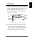
1 Quick Start This chapter provides a quick overview of the steps required for setting up and using HP TopTools Remote Control. If you have experience setting up computer hardware and software, you can use the following section as a brief installation guide. Before installing the HP TopTools Remote Control PCI card, you must already have completed initial installation and configuration of your HP NetServer. For a brief overview of how HP TopTools Remote Control works, see Figure 2-1 before proceeding.
Chapter 1 Quick Start Install and set up hardware at the server (see Chapter 3 for detailed instructions): 1. Mount the battery pack on the HP TopTools Remote Control PCI card and connect the battery cable to the battery pack connector (see Figure 1-1). 2. Connect one end of the supplied I2C/IPMB cable to the connector on the HP TopTools Remote Control card. 3. Install the HP TopTools Remote Control card in one of the server’s free PCI slots.
Chapter 1 Quick Start ◊ If you plan on connecting to the TopTools Remote Control card via modem: Define the card’s PPP settings (modem initialization string, IP Address, Subnet Mask). Typically, you would leave the PPP IP Address and PPP Subnet Mask at the factory defaults since your PPP connection does not interact with the site network. 3. Save the configuration and exit. 4. At a remote client running Microsoft Windows NT 4.
Chapter 1 Quick Start 3. Enter the URL address of the HP TopTools Remote Control card, which should be one of the following: ◊ If connecting via LAN, enter either the card’s IP address (for example: http://xxx.xxx.xxx.xxx/), or a host name, if one has been assigned to the HP TopTools Remote Control card in your DNS server (for example: http://cardname.companyname.com).
2 Introducing HP TopTools Remote Control HP TopTools Remote Control combines an intelligent PCI card and integrated software that provides powerful remote server management. Management capabilities include server status monitoring, configurable event notification, and diagnostic features. The card’s remote management capabilities are accessed using standard web browser software. HP TopTools Remote Control consists of: • The HP TopTools Remote Control card. A PCI card that plugs into your HP NetServer.
Chapter 2 Introducing TopTools Remote Control TopTools dialback capability also provides extra security when communicating with the card via a dial-up modem. How HP TopTools Remote Control Works HP TopTools Remote Control operates independent of the server. It has its own processor chip, a serial and LAN port, and interface. These are completely separate from the server and the server’s Network Operating System (NOS).
Chapter 2 Introducing TopTools Remote Control User receives an email or a page (shown below) that identifies the server and the event code that triggered the notification. 19010 90021 Memory error When a notification-enabled event occurs, HPTopTools Remote Control sends a page or email to the configured user.
Chapter 2 Introducing TopTools Remote Control Documentation HP TopTools Remote Control includes the following documentation: • This guide, which describes how to install the HP TopTools Remote Control and set it up to communicate with the server. • HP TopTools Remote Control online help, which describes all aspects of the user interface including how to use HP TopTools Remote Control to manage your network server. • pcANYWHERE32 online documentation.
Chapter 2 Introducing TopTools Remote Control • TFTP: Trivial File Transfer Protocol. This file transfer protocol allows PUT and GET operations with absolute file names and does not require user authentication. TopTools remote control uses TFTP to implement firmware updates and remote boots. Who Should Use This Guide This guide is designed for system administrators and people who are familiar with installing, managing, and troubleshooting servers on a network.
Chapter 2 Introducing TopTools Remote Control a graceful shutdown (if the NetServer SNMP agent software is installed), a reboot, or a complete power cycle. An administrator can also remotely power off the server if, for example, there has been a critical hardware failure. If text remote control is enabled during server reboot, the actual bootup screens can be viewed at a remote site. Remote configuration.
Chapter 2 Introducing TopTools Remote Control client. This is the same event log available via TopTools when the server is online. Event notification. HP TopTools Remote Control notifies designated users when an event occurs that has been specified for notification. Using Remote Control notification, an administrator’s valuable time is freed from constant surveillance of the server, and server downtime is kept to a minimum.
Chapter 2 Introducing TopTools Remote Control Remotely upgrade firmware. The HP TopTools Remote Control management program code is stored in Flash ROM on the HP TopTools Remote Control card. If it is necessary to upgrade the firmware, a newer revision of the program code may be downloaded via a TFTP server to the programmable ROM (see Appendix C for details). When available, new firmware versions can be obtained from the HP web site. SNMP support.
Chapter 2 Introducing TopTools Remote Control • The server must also have been initially set up with a Network Operating System and the HP NetServer SNMP agents installed. HP TopTools Remote Control uses these agents to perform certain functions. If you are not sure, refer to the HP NetServer SNMP agent installation instructions available from the Information Assistant program on the HP NetServer Documentation CD that came with your NetServer.
Chapter 2 Introducing TopTools Remote Control Dial-up (PPP) Connection Requirements To access HP TopTools Remote Control via modem, you need: • A supported modem (refer to Appendix B) and phone line • MS Windows NT or 95 Dial-up Networking installed. For non-Windows platforms, suitable PPP software installed. • A supported Web Browser (see below) • pcANYWHERE32 Version 8.
3 Hardware Installation and Configuration This chapter provides instructions for installing the HP TopTools Remote Control card in a server and setting up a hardware connection that permits remote management of the server. (See Chapter 4 for information on setting up HP TopTools Remote Control management software.
Chapter 3 Hardware Installation and Configuration Verifying and Updating the Server’s System BIOS To verify that the server’s system BIOS is compatible with HP TopTools Remote Control: 1. Insert the HP NetServer Navigator CD supplied with HP TopTools Remote Control in the NetServer’s CD-ROM drive and reboot. The Navigator CD boots and automatically verifies that the system BIOS and firmware are compatible with HP TopTools Remote Control. 2.
Chapter 3 Hardware Installation and Configuration CAUTION The HP TopTools Remote Control card is sensitive to static electricity and can easily be damaged by improper handling. Use of an antistatic service kit, such as 3M® 8501/8502/8505 or equivalent is recommended. To mount the battery pack: 1. Place the HP TopTools Remote Control card on a clean non-conductive surface and disconnect the battery cable from the card. 2.
Chapter 3 Hardware Installation and Configuration 4. Plug in the cable leading from the battery pack into the battery connector on the card (refer to Figure 3-1). For proper operation make sure that the battery is fully charged after installation into the server. Charging takes about two hours after the server has been powered up, or after the optional AC/DC power adapter has been plugged in. CAUTION The battery pack is already pre-charged.
Chapter 3 Hardware Installation and Configuration 2. Plug in either end of the I2C cable (HP Part Number 5183-6569). Note: I2C cable end connectors are identical Figure 3-3: I2C cable Installing the TopTools Remote Control Card in the Server The exact procedure for installing the HP TopTools Remote Control PCI card depends on your particular server model. For specific information about installing a PCI card in your server, refer to the user guide supplied with your server.
Chapter 3 Hardware Installation and Configuration The I2C cable is both color coded and keyed to plug in to the I2C/IPMB connector only one way. HP does not support installations of the HP TopTools Remote Control card in systems that do not include the I2C/IPMB feature. Currently, these include systems such as the HP NetServer LC 3, LH 3 and LH 4. To find out if your server includes an I2C/IPMB connector, refer to your server documentation.
Chapter 3 Hardware Installation and Configuration 5 volt DC input Figure 3-5. Plugging in the Optional AC/DC Adapter 3. HP recommends that you attach the AC/DC adapter directly to the server housing using tie wraps to ensure that the power supply cable to the card isn’t accidentally disconnected. CAUTION Do not power down a server with an installed HP TopTools Remote Control card if the card’s battery is weak and the card does not have an AC/DC adapter plugged in.
Chapter 3 Hardware Installation and Configuration Self Test Power Up Sequence During the HP TopTools Remote Control card’s self test, observe the diagnostic LEDs located just above the card’s RS-232 port (refer to Figure 3-6). 1. The green (heartbeat) LED and the red (error) LED switch on for about 10 seconds. 2. If no errors are detected, the green heartbeat LED flashes every 5 seconds, indicating normal operation. After initial power-up, the red LED should not be visible. 3.
4 Setting Up the Remote Connection This chapter describes how to cable and configure the remote communications link to HP TopTools Remote Control card (LAN or modem). Once communications have been established, you may control your HP NetServer using the HP TopTools Remote Control web interface. NOTE If you have not provided for an independent communications link to the card (either via a dedicated LAN line or dial-up modem line), you will be unable to communicate with the HP TopTools Remote Control card.
Chapter 4 Setting Up the Remote Connection Regardless of the type of physical connection joining the TopTools Remote Control card and remote client, you must initially use the HP TopTools Remote Control BIOS setup program at the server (described in the next section) to configure a communications link between the HP TopTools Remote Control card and a remote client.
Chapter 4 Setting Up the Remote Connection HP TopTools Remote Control for HP NetServers Card Setup LAN Settings PPP Settings Remote Boot Settings Firmware Update Settings Exit Figure 4-2. Main Setup Screen The displayed value on any of the setting screens is updated as soon as an entered value is validated. LAN Configuration For a remote connection to the TopTools Remote Control card via LAN, the LAN Settings screen is used to set up the connector on the card.
Chapter 4 Setting Up the Remote Connection If DHCP is enabled, the next time the HP TopTools Remote Control card reboots it will obtain its network settings (including its IP address) from the DHCP server. The card will attempt to keep the assigned network settings for as long as possible so you won’t need to go back into the card’s BIOS setup program to view a new IP address (or view the card’s new address via HP TopTools Device Manager) every time the card reboots.
Chapter 4 Setting Up the Remote Connection Remote Boot Configuration The HP TopTools Remote Control card is able to boot the server using a boot floppy image file located on a TFTP server (see Appendix C for detailed information about TFTP remote boot setup). This feature can also be configured at the remote client using the TopTools Remote Control web interface software. To use the remote boot feature: 1. Set Remote Boot to "on.
Chapter 4 Setting Up the Remote Connection download the desired version onto your card. Note that once you select "Start Firmware Update" the update begins immediately. HP TopTools Remote Control for HP NetServers - Firmware Update Settings Start Firmware Update Set Firmware Image Filename firmimg.bin Set IP-Address of Firmware TFTP Server 127.0.0.1 Main Menu Figure 4-6.
Chapter 4 Setting Up the Remote Connection To enable remote connection over your local area network, LAN settings must have been defined in the card’s BIOS setup program (see previous section). Remote Client Configuration (LAN) Your remote client should already be set up and connected to your local area network. Verify that TCP/IP protocol is set up properly for the client (client’s IP Address, Subnet Mask, and Gateway) by checking its properties from the Network program in the Control Panel.
Chapter 4 Setting Up the Remote Connection NOTE HP recommends that you supply power to your external modem from an Uninterruptible Power Supply (UPS), so that you can be notified in case of an AC line power failure. Remote Client Configuration (PPP/Dial-Up Networking) This section describes using dial-up networking for a Windows NT 4.0 client. Windows 95 and 98 configuration steps are similar.
Chapter 4 Setting Up the Remote Connection Figure 4-9. Example: Configuring Dial-Up Networking in Windows NT 4.0 5. Under "More," select "Edit entry and modem properties." Here you can set up modem configuration using the "Basic" tab. 6. Click the "Server" tab to specify the dial-up server type, network protocols, and compression. Make sure your settings match the following figure. (If you have Windows 95, make sure you do not check the "Login to network" option.
Chapter 4 Setting Up the Remote Connection Figure 4-10. Define the Dial-Up Server Type 7. Click the "TCP/IP Settings" button (see Figure 4-11). Select the "Server assigned IP address" option. The client will automatically get an IP Address from the HP TopTools Remote Control card. Check "Specify name server addresses" and make sure all DNS and WINS entry fields are set to zero (0). Uncheck "Use default gateway on remote network." Click OK.
Chapter 4 Setting Up the Remote Connection Figure 4-11. Define TCP/IP Settings 8. Click the "Script" tab. To expedite the TopTools Remote Control login process, use the script provided by HP included on the HP NetServer Navigator CD in \ttrc\us\ttrc.scp. Copy this script file to your remote client and enter that path in the script dialog box.
Chapter 4 Setting Up the Remote Connection Figure 4-12. Configure Script If you don’t wish to use the script, select "Pop up a terminal window" instead. 9. Click the "Security" tab and select "accept only encrypted authentication". 10. You may now dial up to establish the modem connection to the card using the card’s external modem phone number. Once connected, you will see a modem connection icon on the task bar of your desktop. When you are ready to make your first connection, proceed to Chapter 5.
5 Logging In and Using the HP TopTools Remote Control Web Interface After you’ve installed, cabled, and configured the HP TopTools Remote Control card using the card’s BIOS setup program, you are ready to set options for the Remote Control card using HP TopTools Remote Control’s management software.
Chapter 5 Logging In and Using the TopTools Remote Control Web Interface Logging In to HP TopTools Remote Control To initiate a connection to HP TopTools Remote Control from the remote client, connect to HP TopTools Remote Control via LAN or modem connection, as follows: 1. If you are using a modem (PPP) at the remote client (proceed to step 2 if you are not), make your connection using the Dial-Up Networking program.
Chapter 5 Logging In and Using the TopTools Remote Control Web Interface Click here for HP TopTools Remote Control Online Help Figure 5-1. HP TopTools Remote Control Web Interface Software 4. Click the Configuration tab. The login prompt is displayed. 5. In the User Name field, enter a valid administrator name. For your first login, the factory default name is ADMIN. 6. At the password prompt, enter the password that belongs to the administrator name.
Chapter 5 Logging In and Using the TopTools Remote Control Web Interface some administration actions on multiple cards at once. See online help for details (click the "?" button in the upper right corner of the browser window). Using the HP TopTools Remote Control Web Interface You can use HP TopTools Remote Control web interface to remotely manage the server in which you have installed the HP TopTools Remote Control card.
Chapter 5 Logging In and Using the TopTools Remote Control Web Interface • Support. Provides listings of additional user resources relative to server configuration and management. Best used when also connected to the World Wide Web for ready access to HP’s web pages. • Use with TopTools Device Manager. TopTools Remote Control fully integrates with the TopTools Device Manager product (version 4.1x and above).
6 Setting Up NT Graphics Console Redirection Using pcANYWHERE32 For NetServer systems running Microsoft Windows NT 3.51 or 4.0, you can redirect the server’s NT graphics console to a remote PC client to remotely perform operations as if you were sitting at the server. To do this, you must install pcANYWHERE32 software. pcANYWHERE32 components must be installed and configured at both the server and the remote client to use NT remote control.
Chapter 6 Setting Up NT Graphics Console Redirection Using pcANYWHERE32 Installing pcANYWHERE32 on the Server To enable console redirection (the ability to redirect what’s graphically displayed on your server) either over the LAN or via modem, you must first install the pcANYWHERE32 host software, included with your system, on your HP NetServer.
Chapter 6 Setting Up NT Graphics Console Redirection Using pcANYWHERE32 4. Run the pcANYWHERE32 setup program. From the Windows Start menu, click "Run" and browse to the setup program’s location: x:\util\pca32\us\disk1\setup.exe where x: is the letter of your CD-ROM drive. Follow the on-screen setup instructions. 5. When setup is complete, you are prompted to restart. Remove the HP NetServer Navigator CD and click OK.
Chapter 6 Setting Up NT Graphics Console Redirection Using pcANYWHERE32 3. Make a new connection item for your server. Double-click the "Add Be a Host PC Item". 4. Configure the connection item for LAN or modem use. ◊ LAN connection: Select TCP/IP as the connection device. ◊ Modem connection: You will be prompted for a Host Name and connection device. Select the COM port (not modem) assigned by the HP TopTools Remote Control card’s serial driver (see previous section).
Chapter 6 Setting Up NT Graphics Console Redirection Using pcANYWHERE32 5. Click OK then Next and deselect the checkbox to "Automatically launch after wizard," then click Finish. Your new connection item appears in the pcANYWHERE32 main window. 6. Right-click your new connection item and click "Properties". 7. From the Properties menu, click the Settings tab and check the "Launch with Windows" and "Run minimized" checkboxes. Click OK to return to the main program window. 8.
Chapter 6 Setting Up NT Graphics Console Redirection Using pcANYWHERE32 Console Redirection Over a LAN If you want console redirection (remote control) of your server over a LAN (instead of using a modem with pcANYWHERE32), you must have TCP/IP software installed on your client. TCP/IP is available with the standard Windows NT product.
Chapter 6 Setting Up NT Graphics Console Redirection Using pcANYWHERE32 2. At the pcANYWHERE32 main screen, click the Remote Control action button from the action button bar. You will see the Remote Control connection items displayed. Figure 6-4. pcANYWHERE32 Remote Control Connection Items 3. Create a new connection item to access your HP NetServer by doubleclicking the "Add Remote Control Item". An installation Wizard prompts you for information needed to set up a new connection item. 4.
Chapter 6 Setting Up NT Graphics Console Redirection Using pcANYWHERE32 To complete configuration of the connection item, proceed to the appropriate section below. LAN Connection 1. Highlight the TCP/IP option in the list of connection devices and click "Details". 2. Enter Gateway information if necessary, then click OK. 3. Identify the Host PC’s name (or IP Address for the host HP NetServer), then click "Next".
Chapter 6 Setting Up NT Graphics Console Redirection Using pcANYWHERE32 Customizing Your Connection Items If you want to rename a connection item, right-click it, select Rename, and type in a new name. You can also copy, paste, and reconfigure a connection item to create an icon for each server you manage. Installation and configuration of pcANYWHERE32 at the client is now complete. Proceed to the next section for instructions on the use of pcANYWHERE32 to redirect the NT graphics console.
Chapter 6 Setting Up NT Graphics Console Redirection Using pcANYWHERE32 5. Start pcANYWHERE32. Double-click the remote control connection item for the server’s HP TopTools Remote Control card. pcANYWHERE32 connects to the server and begins redirecting the NT console. For more information on using Windows NT console redirection, or for details about pcANYWHERE32 features, refer to the online pcANYWHERE32 User Guide.
7 Troubleshooting This chapter provides some guidelines for troubleshooting HP TopTools Remote Control card. Different sections highlight difficulties related to: • Installation problems • Paging concerns • Remote client issues Problems with Installation The HP TopTools Remote Control card does not respond. Make sure that the HP TopTools Remote Control card is securely seated in a PCI slot. Check the diagnostic LEDs located above the RS-232 port on the back panel of the card.
Chapter 7 Troubleshooting If your pager service generates repetitive tones when it answers, the HP TopTools Remote Control modem may interpret the tones as a busy signal and attempt to re-dial. To prevent this, change the X4 command in the modem initialization string to X0 (blind dialing).
Chapter 7 Troubleshooting 20204 TAP: No message go ahead Event code 20204 occurs when the Terminal Logon is not accepted. This indicates that: 1. Your terminal has required more information than HP TopTools Remote Control is configured to send. 2. Your paging service provider is not completely adhering to the alphanumeric paging protocols. If this appears to be the case, call HP Technical Support. 3. It is also possible that you are not dialing the correct modem access number.
Chapter 7 Troubleshooting Remote Client I cannot log into HP TopTools Remote Control from the remote client. Are you entering the correct password? The login name and password are case sensitive. The factory default login name is ADMIN. Likewise, the factory default login password is ADMIN. I can no longer communicate with HP TopTools Remote Control from the remote client. If DHCP is enabled for the HP TopTools Remote Control card, the IP address on the card may have changed.
Chapter 7 Troubleshooting access especially when the connection is forgotten. An administrator may change the default automatic logout time. The keys I type from the remote client don’t appear on the server screen. Type in the keyboard lock password to unlock the keyboard. The keyboard remains unlocked until the next system reboot. If the password does not enable the keyboard, try toggling the Numlock key at the server to enable the numeric keypad. My power control functions appear to be disabled.
Chapter 7 Troubleshooting I forgot my password and can no longer log into the card. If you are the TopTools Remote Control card administrator and have forgotten your password, there is a special utility on the HP NetServer Navigator CD that will allow you to reset the TopTools Remote Control user database back to the factory defaults (Login=ADMIN, Password=ADMIN). Note that doing this will erase all existing user account information.
A Event Codes The table below describes the event codes that can be listed in the event log and optionally directed to specified users via e-mail or pager. When the HP TopTools Remote Control card sends notification about a server event, it includes the server identifying number and a five-digit code identifying the event. (If you use email or a TAP pager, you will receive the server name and some descriptive text as well.
Appendix A Event Codes Event Code Severity Description 00901 Warning Redundant Power Supply Unit Redundancy Lost None 00906 Critical Redundant Power Supply Critical # of Power Supply Units None 20100 Informational Remote Initiated None 20101 Informational Remote Initiated Reset None 20102 Informational Remote Initiated Power Cycle None 20103 Informational Remote Initiated Power Down None 20104 Informational Remote Initiated Power Up None 20105 Non-recoverable
Appendix A Event Codes Event Code Severity Description Agent 01703 Non-recoverable OS Watchdog Power Down None 01704 Non-recoverable Server Power Cycled after NOS Hang (ASR) None 01706 Non-recoverable Warning NOS Hang (ASR) None POST Errors 01520 POST Error None Security 00530 Warning Chassis Intrusion None 20000 Warning Illegal Login Threshold None 20001 Informational Remote User Login None 20002 Informational Remote User Logout None 20003 Informational Autologout No
Appendix A Event Codes Event Code Severity Description Agent 20403 Warning Battery Low None 20404 Warning Battery Disconnected None 20405 Warning Configuration Info.
Appendix A Event Codes Event Code Severity Description Agent 21108 Informational Host Adapter Discovered SCSIFLT/ SMART 21109 Informational Host Adapter Changed SCSIFLT/ SMART 21110 Critical Host Adapter Failed SCSIFLT/ SMART 21111 Informational Host Adapter Recovered SCSIFLT/ SMART 21112 Warning Device Failed SCSIFLT/ SMART 21113 Warning SCSI Device Discovered SCSIFLT/ SMART 21114 Warning SCSI Device Recovered SCSIFLT/ SMART 21115 Warning SCSI Device Changed SCSIFLT/ SM
Appendix A Event Codes Event Code Severity Description Agent SMART 21138 Informational Host Adapter Discovered SCSIFLT/ SMART 21139 Informational Host Adapter Changed SCSIFLT/ SMART 21140 Critical Host Adapter Failed SCSIFLT/ SMART 21141 Informational Host Adapter Recovered SCSIFLT/ SMART 21142 Warning SCSI Device Failed SCSIFLT/ SMART 21143 Warning SCSI Device Discovered SCSIFLT/ SMART 21144 Warning SCSI Device Recovered SCSIFLT/ SMART 21145 Warning SCSI Device Changed
Appendix A Event Codes Event Code Severity Description Agent 21211 Warning Check Consistency Corrected NetRAID DAC 21212 Warning Check Consistency Failed NetRAID DAC 21213 Warning Reconstruction Started NetRAID DAC 21214 Warning Reconstruction Completed NetRAID DAC 21215 Warning Reconstruction Failed NetRAID DAC 21216 Warning Physical Drive Predictive Failures NetRAID DAC 21217 Warning Physical Drive Failure Prediction Threshold Exceeded NetRAID DAC 21218 Warning Physical
Appendix A Event Codes Event Code Severity Description Agent 21902 Critical A physical device reports a hard error FCARRAY 21903 Warning A physical device predicted potential failure (PFA/SMART) FCARRAY 21904 Informational Automatic rebuild started FCARRAY 21905 Informational Manual rebuild started FCARRAY 21906 Informational Rebuild completed FCARRAY 21907 Informational Rebuild canceled FCARRAY 21908 Critical Rebuild error FCARRAY 21909 Critical Rebuild failed due to new
Appendix A Event Codes Event Code Severity Description Agent 21936 Informational Logical device became on-line FCARRAY 21937 Informational Automatic rebuild started FCARRAY 21938 Informational Manual rebuild started FCARRAY 21939 Informational Rebuild completed FCARRAY 21940 Informational Rebuild canceled FCARRAY 21941 Critical Rebuild error FCARRAY 21942 Critical Rebuild failed due to new physical device FCARRAY 21943 Non-recoverable Rebuild failed due to logical device
Appendix A Event Codes Event Code Severity Description Agent 21970 Non-recoverable Controller offline FCARRAY 21971 Critical Controller’s partner is gone FCARRAY 21972 Informational Battery Backup Unit Recondition Start FCARRAY 21973 Informational Battery Backup Unit Recondition Finished FCARRAY 21974 Informational Battery Backup Unit Recondition canceled FCARRAY 21975 Informational Physical device size table is full FCARRAY 21976 Non-recoverable Storage cabinet fan Failed F
Appendix A Event Codes Event Code Severity Description Agent 21342 Warning Adapter reset errors exceeded absolute threshold NIC 21343 Warning Alignment errors exceeded absolute threshold NIC 21344 Warning Giant frame errors exceeded absolute threshold NIC 21345 Warning Hardware mismatch errors exceeded absolute threshold NIC 21346 Warning Late collision errors exceeded absolute threshold NIC 21347 Warning Excessive collision errors exceeded absolute threshold NIC 21348 Warning
Appendix A Event Code Event Codes Severity Description Agent Other 21401 Warning Tape Read Problems TapeAlert 21402 Warning Tape Write Problems TapeAlert 21403 Warning Tape Read/Write Data Error TapeAlert 21404 Warning Tape Faulty Media TapeAlert 21405 Warning Tape Read Fault TapeAlert 21406 Warning Tape Write Fault TapeAlert 21407 Warning Tape Worn Out Media TapeAlert 21408 Warning Tape Substandard Media TapeAlert 21409 Warning Tape Write Protected TapeAlert 21410
Appendix A Event Codes Event Code Severity Description Agent 21441 Warning Tape Autoloader Stray Tape TapeAlert 21442 Warning Tape Autoloader Mechanism Fault TapeAlert 21443 Warning Tape Autoloader Door Open TapeAlert 21444 Warning Tape Autoloader Door Hardware Fault: Call Helpline TapeAlert 21445 Warning Tape Autoloader Door Needs Magazine TapeAlert 21446 Warning Tape Device Predicted to Fail: Call Helpline TapeAlert 21447 Warning Tape Autoloader Door Needs Magazine TapeAle
Appendix A Event Codes Event Code Severity Description 21504 Critical APC UPS Discharged Battery APC/UPS 21505 Warning APC UPS on Battery APC/UPS 21506 Warning APC UPS Smart-Boost Enabled APC/UPS 21507 Critical APC UPS Low Battery APC/UPS 21508 Informational APC UPS Communication Established APC/UPS 21509 Informational APC UPS A/C Power Restored APC/UPS 21510 Informational APC UPS Self-Test Passed APC/UPS 21511 Informational APC UPS Return from Low Battery APC/UPS 21513
B Recommended Modems For modem connection to the HP TopTools Remote Control card, an external modem is required. HP recommends that you use the same model (or at least the same brand) of modem at the remote client that you use at the server. A list of recommended modems with their initialization strings for PPP communication and numeric paging is listed in Table B-1 below. Table B-1.
Appendix B Recommended Modems Getting the Latest Recommended Modems List An updated list of recommended modems may be found on the HP NetServer Tested Products List. To review the Tested Products List, go to either: • HP NetServer Navigator CD: To access the modem list from the HP NetServer Navigator CD: 1. Insert the HP NetServer Navigator CD into a client with a CD-ROM drive. 2. Run Windows Explorer and double-click on the TPL.HLP file located in the TPL directory.
C Installing and Using TFTP Overview: What Is TFTP? TFTP, the Trivial File Transfer Protocol, allows the HP TopTools Remote Control card to access boot floppy images and new firmware images stored at a LAN or modem-connected computer. TFTP is built on top of TCP/IP and is functionally a subset of FTP. As its name indicates, this protocol is used to transfer data between a "TFTP server" and either the HP TopTools Remote Control or some other device that acts as the "TFTP client.
Appendix C Installing and Using TFTP HP NetServer with TopTools Remote Control card Local system with TFTP Server Software and firmware or floppy image LAN OR LAN or PPP (Modem) Remote Client with TFTP Server Software and firmware or floppy image (firmware update of TopTools Remote Control Card NOT allowed using PPP) Figure C-1.
Appendix C Installing and Using TFTP TFTP Requirements To use the TFTP service with HP TopTools Remote Control, you must have: • TFTP client software. The client software is already built into the firmware of the HP TopTools Remote Control card. • TFTP server software (tftpserv.exe). To run tftpserv you need one of the following operating systems: ◊ ◊ ◊ Microsoft Windows NT 4.0 Microsoft Windows NT 3.
Appendix C Installing and Using TFTP To configure the Remote Control card for firmware updates, use one the following procedures: Update Option 1 1. Shutdown and reboot the HP NetServer containing the HP TopTools Remote Control card. 2. Enter the BIOS setup interface by pressing F3 when prompted during HP NetServer boot. 3. Select " Firmware Update Settings", and enter the IP address of the TFTP server and the filename of the firmware image.
Appendix C NOTE Installing and Using TFTP HP recommends that you do not update the HP TopTools Remote Control card firmware if the link between the TFTP server and the HP NetServer is a dial-up network connection. A disconnection during an update can leave the HP TopTools Remote Control card partially updated and you would need to repeat the update before proceeding. A firmware update takes approximately one minute over a 10Base-T LAN connection.
Appendix C NOTE Installing and Using TFTP Check the HP NetServer’s BIOS Setup program (typically, accessed by pressing F2 when prompted during the boot process) to ensure that the floppy drive is positioned at the top of the list of bootable devices in the boot order. Creating a Floppy Boot Image Before you can create a boot image, you must get a copy of the HP utility "copydisk.exe". NOTE Do not confuse HP’s copydisk.exe with the DOS utility diskcopy.
Appendix C Installing and Using TFTP where a: is the source diskette and x:\path\filename is the destination drive, path and filename with a .dsk extension for your image file. An image file is created and transferred to the designated directory. Initiating a Remote Boot Using a Floppy Boot Image There are two ways to boot the HP NetServer using a remote boot image: • Remote Boot Option 1 requires "hands-on" access at the HP NetServer.
Appendix C Installing and Using TFTP ◊ Power on (if the server is off) ◊ Power cycle ◊ Reset Once you have selected an action that would bring the HP NetServer back online, you can further select Remote Boot features. 3. Select Remote Boot. This enables HP TopTools Remote Control to retrieve a floppy disk image from the designated remote computer. 4. Enter the IP Address of the TFTP server and the filename of the boot image. The filename you specify should be a relative path from the root directory.
Appendix C Installing and Using TFTP Example 1: A remote server BIOS update In this example, the system administrator wants to update the BIOS of a remote HP NetServer. The administrator first obtains the latest BIOS from the HP web site and downloads it to a local hard disk. The administrator then runs the self extracting BIOS update file and copies the biosxyz.dsk file to the tftpserv base directory. The administrator then uses TopTools Remote Control to remote boot the biosxyz.dsk BIOS update disk.
Appendix C Installing and Using TFTP 2. Select HP Diagnostic Assistant and follow the instructions to create the floppy in drive A. 3. Using the Copydisk program, create a floppy boot image in the base directory of your TFTP server. Use the following syntax: copydisk a: x:\path\diagasst.dsk where a: is the source diskette and x:\path is the destination TFTP base directory on your hard drive. 4. Run tftpserv.exe. TFTP waits for a request for an image file from the TopTools Remote Control card. 5.
Appendix C Installing and Using TFTP 2. Obtain the new driver (in this case AIC7870.dsk). Go to HP’s NetServer web site (www.hp.com/go/netserver) and download the appropriate driver from the HP’s NetServer Service and Support page. 3. Copy the driver file to the formatted floppy in drive A. Copy the DOS editor to the floppy (in Windows 95, this file is located in: \windows\command\edit.com). 4. Create an autoexec.bat file on the floppy that includes the following command lines: mkdir c:\temp copy aic7870.
D Technical Specifications This appendix provides specifications for the HP TopTools Remote Control PCI card.
Appendix D Technical Specifications Feature Description Optional AC/DC Power Adapter Input voltage: 100 - 240 V AC, 50/60 Hz Output voltage: 5V ± 5 % Output current: 2.0 A max. Operating temperature: 0 degrees to 40 degrees C Certification: CSA, C22.2 No 950-95, EN 60950, CE * For optimal battery lifetime, the temperature inside the server should be maintained below 40 degrees C and should never exceed 50 degrees C.
E Battery Operation The HP TopTools Remote Control card includes a rechargeable Nickel Metal-Hydride (NiMH) battery pack that ensures a supply of power to the card components. This battery pack contains four cells and is rated at 4.8V at 1100mAH. In case of a loss of AC power to the server, or a power supply failure, the battery continues to power the HP TopTools Remote Control for up to one hour.
Appendix E Battery Operation The HP TopTools Remote Control card also provides the following alternate charging modes: • Fast charge. If the card determines that the battery has been depleted, it begins a fast charge. • Trickle charge. When the battery is fully charged, the card switches to a trickle-charge mode of operation. When power is first applied to the card, the battery is always initially fast charged. (This is true even if the battery is already fully charged.
Appendix E Battery Operation Replacement To replace the HP TopTools Remote Control battery pack (Part No. 5183-6570) contact your HP Sales and Service office. In the U.S. call (800) 227-8164. To order a replacement battery pack from Hewlett-Packard, refer to its Part Number. Battery Disposal Nickel Metal-Hydride batteries should be disposed of in a responsible fashion according to the laws in the country where the card is used. CAUTION Do not crush, puncture, or incinerate the battery.
F LED Codes A failure on the HP TopTools Remote Control card is indicated by a flashing signal pattern displayed by the red diagnostic LED visible above the RS-232 port (refer to Figure F-1). The other set of LEDs located next to the LAN port indicate LAN connection activity. NOTE In the event that more than one error is affecting card operation, the HP TopTools Remote Control reports only the first failure discovered. Diagnostic LEDs LAN LEDs LAN Connector Figure F-1.
Appendix F LED Codes For example, a 2-1-1-2 error (DRAM Error) would appear as: flash-flash, pause, flash, pause, flash, pause, flash-flash, pause The failure pattern repeats indefinitely. Failure Codes The table below lists the error or report codes, which are flashed by the HP TopTools Remote Control card’s red diagnostic LED. A flashing red LED always indicates a problem with the card’s operation.
Appendix F LED Codes Action 2: The card firmware may be corrupted and require updating. You may either use the firmware image that came with the card on the HP NetServer Navigator CD, or you may download the latest firmware update image from the HP NetServer BBS or web site (see Technical Support in Appendix H). This image should be copied to your TFTP server (to use the TFTP software, refer to Appendix C). If you are unable to complete this procedure, call your local support center.
G Keyboard Layouts The HP TopTools Remote Control allows an administrator to select a keyboard layout that matches the server keyboard. With the proper keyboard layout, HP TopTools Remote Control is able to correctly interpret keystrokes sent to the server keyboard. HP TopTools Remote Control includes support for France, Italy, Germany, Spain, United Kingdom, and United States keyboards. The graphics below provide layouts for each of the keyboards supported by the HP TopTools Remote Control.
Appendix G 96 Keyboard Layouts
H Software License, Warranty, Regulatory and Support Hardware Product Limited Warranty Hewlett-Packard Hardware Accessories HP warrants this HP NetServer Hardware Accessory against defects in material and workmanship under normal use, for a period of one year. The warranty commences on receipt of this product by Customer from HP or Reseller.
Appendix H Software License, Warranty, Regulatory and Support reasonable amount of time, Customer’s alternate remedy shall be a refund of the purchase price upon return of the product and all copies. Removable Media HP warrants the removable media, if supplied, upon which this product is recorded to be free from defects in materials and workmanship under normal use for a period of ninety (90) days from the date of purchase.
Appendix H Software License, Warranty, Regulatory and Support HP Software License Agreement ATTENTION: USE OF THE SOFTWARE IS SUBJECT TO THE HP SOFTWARE LICENSE TERMS SET FORTH BELOW. USING THE SOFTWARE INDICATES YOUR ACCEPTANCE OF THESE LICENSE TERMS. IF YOU DO NOT ACCEPT THESE LICENSE TERMS, YOU MAY RETURN THE SOFTWARE FOR A FULL REFUND. IF THE SOFTWARE IS BUNDLED WITH ANOTHER PRODUCT, YOU MAY RETURN THE ENTIRE UNUSED PRODUCT FOR A FULL REFUND.
Appendix H Software License, Warranty, Regulatory and Support No Disassembly or Decryption. You may not disassemble or decompile the Software unless HP’s prior written consent is obtained. In some jurisdictions, HP’s consent may not be required for limited disassembly or decompilation. Upon request, you will provide HP with reasonably detailed information regarding any disassembly or decompilation. You may not decrypt the Software unless decryption is a necessary part of the operation of the Software.
Appendix H Software License, Warranty, Regulatory and Support guarantee that interference will not occur in a particular installation. If this equipment does cause harmful interference to radio or television reception, which can be determined by turning the equipment off and on, the user is encouraged to correct the interference by one or more of the following measures: • Reorient or relocate the receiving antenna. • Increase the separation between the equipment and the receiver.
Appendix H Software License, Warranty, Regulatory and Support DECLARATION OF CONFORMITY per ISO/IEC Guide 22 and EN 45014 Manufacturer’s Name: Manufacturer’s Address: Hewlett-Packard Company 5301 Stevens Creek Blvd.
Appendix H Software License, Warranty, Regulatory and Support Technical Support During the warranty period, telephone technical support is available to assist with setup, configuration, startup, and troubleshooting of your hardware product. Prior to calling HP or Reseller, please follow this checklist. This will allow HP or Reseller to assist you more quickly and efficiently. 1. Consult the documentation provided with your product to assure that your system features are properly configured. 2.
Appendix H Software License, Warranty, Regulatory and Support Europe For hardware service and telephone support, contact either: • A participating Reseller or • HP Customer Support Center (Netherlands): Austria: 0660 6386 Netherlands: 020 6068751 Belgium (Dutch): 02 626 8806 Norway: 22 11 6299 Belgium (French): 02 626 8807 Portugal: 01 441 7199 Denmark: 3929 4099 Spain: 902 321 123 Finland: 02 03 47 288 Sweden: 08 619 2170 France: 01 43 62 3434 Switzerland: 084 880 1111 Germany:
Index A AC/DC Adapter connecting optional adapter, 20 acronyms, 8 Agents, NetServer, 13 audience, 9 Automatic Server Restart (ASR), 11 Automatic server shutdown, 11 B Battery disposal, 89 Battery operation, 87 cabling configuration, 17 charging, 87 life expectancy, 88 limited card function when running on low battery, 88 mounting the battery pack, 16 shutting down the board, 87 Battery replacement, 89 BIOS setup program, 24 updating the system, 16 C Configurable options in web interface, 35 configuration HP
Index HP TopTools Remote Control Card configuring, 24 connecting the I2C cable, 18 features, 9 how it works, 6 installing, 19 overview, 5 preparing the card, 16 remote login, 36 setting up, 15 technical specifications, 85 troubleshooting, 51 verifying installation, 21 HP TopTools Remote Control features Automatic Server Restart, 11 automatic server shutdown, 11 console redirection, 9 diagnostics, 11 dialback, 10 DOS file transfer, 11 logging server events, 10 memory diagnostics, 11 on-board processor, 9 PC
Index P package contents, 7 Paging Troubleshooting, 51 password resetting to the factory defaults, 56 pcANYWHERE32 client LAN connection, 48 client PPP connection, 48 configuring on the server, 43 configuring remote client software, 46 overview, 41 remote client software installation, 45 server installation, 42 server side toolbar, 47 server-side toolbar, 43 pcANYWHERE32 documentation, 8 PCI bus efficiency, 10 PCI bus utilization, 10 performance monitoring, 10 Power control cable installing, 18, 20 PPP def
Index requirements, 75 updating firmware, 75 using, 73 TFTP defined, 9 TopTools Remote Control Card limited card function when running on low battery, 88 troubleshooting, 51 Troubleshooting installation, 51 Notification, 51 Paging, 51 remote client, 54 TAP event codes, 52 U upgradeable firmware, 12 108 V verifying card installation, 21 Voltage emergency shutdown, 11 W warranty information, 97 web browser supported, 14 web interface, 5, 37 logging in, 35 online help, 39 using, 38 Web interface configurabl