Hardware Reference Guide HP Compaq Business Desktop dc5000 Small Form Factor Model Document Part Number: 359513-001 January 2004 This guide provides basic information for upgrading this computer model.
© Copyright 2004 Hewlett-Packard Development Company, L.P. The information contained herein is subject to change without notice. Microsoft, MS-DOS, Windows, and Windows NT are trademarks of Microsoft Corporation in the U.S. and other countries. Intel, Pentium, Intel Inside, and Celeron are trademarks of Intel Corporation in the U.S. and other countries. Adobe, Acrobat, and Acrobat Reader are trademarks or registered trademarks of Adobe Systems Incorporated.
Contents 1 Product Features Standard Configuration Features. . . . . . . . . . . . . . . . . . . . . . . . . . . . . . . . . . . . . . . . . . Front Panel Components . . . . . . . . . . . . . . . . . . . . . . . . . . . . . . . . . . . . . . . . . . . . . . . . Rear Panel Components . . . . . . . . . . . . . . . . . . . . . . . . . . . . . . . . . . . . . . . . . . . . . . . . Keyboard . . . . . . . . . . . . . . . . . . . . . . . . . . . . . . . . . . . . . . . . . . . . . . . . . . . . . . . . . . . .
Contents A Specifications B PATA Hard Drive Installation Guidelines Using the Cable-Select Feature with Parallel ATA (PATA) Devices. . . . . . . . . . . . . . B–1 Guidelines for Installing PATA Drives . . . . . . . . . . . . . . . . . . . . . . . . . . . . . . . . . B–1 C Battery Replacement D Security Lock Provisions Installing a Security Lock . . . . . . . . . . . . . . . . . . . . . . . . . . . . . . . . . . . . . . . . . . . . . . . D–1 E Port Security Bracket Installing the Port Security Bracket. .
1 Product Features Standard Configuration Features The HP Compaq Small Form Factor features may vary depending on the model. For a complete listing of the hardware and software installed in the computer, run the Diagnostics for Windows utility. Instructions for using this utility are provided in the Troubleshooting Guide on the Documentation CD. use the computer in a minitower configuration, you must purchase ✎ Toa tower stand from HP (part number 316593-001).
Product Features Front Panel Components Drive configuration may vary by model.
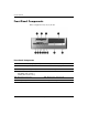
Product Features Rear Panel Components Rear Panel Components 1 Power Cord Connector 7 n RJ-45 Network Connector 2 Voltage Select Switch 8 l Parallel Connector PS/2 Mouse Connector 9 c Monitor Connector 3 b 4 a PS/2 Keyboard Connector - h Headphone/Line-Out Connector 5 o Universal Serial Bus (USB) q j Line-In Audio Connector 6 m w g Microphone Connector ✎ Serial Connector Arrangement and number of connectors may vary by model.
Product Features Keyboard Keyboard Components 1 Function Keys Perform special functions depending on the software application being used. 2 Editing Keys Includes the following: Insert, Home, Page Up, Delete, End, and Page Down. 3 Status Lights Indicate the status of the computer and keyboard settings (Num Lock, Caps Lock, and Scroll Lock). 4 Numeric Keys Work like a calculator keypad. 5 Arrow Keys Used to navigate through a document or Web site.
Product Features Keyboard Components (Continued) 8 Windows Logo Key* Used to open the Start menu in Microsoft Windows. Used in combination with other keys to perform other functions. 9 Alt Key Used in combination with another key; its effect depends on the application software you are using. *Keys available in select geographic regions. Windows Logo Key Use the Windows Logo key in combination with other keys to perform certain functions available in the Windows operating system.
Product Features Special Mouse Functions Most software applications support the use of a mouse. The functions assigned to each mouse button depend on the software applications you are using. Serial Number Location Each computer has a unique serial number that is located on the top cover or the back panel of the computer. Keep this number available for use when contacting customer service for assistance. Serial Number Location 1-6 www.hp.
2 Hardware Upgrades Serviceability Features This computer includes features that make it easy to upgrade and service. No tools are needed for most of the installation procedures described in this chapter. Warnings and Cautions Before performing upgrades be sure to carefully read all of the applicable instructions, cautions, and warnings in this guide.
Hardware Upgrades Using the Small Form Factor Computer in a Minitower Configuration The Small Form Factor computer can be used in either a minitower or desktop configuration. To use it in the minitower configuration, you must purchase a tower stand from HP (part number 316593-001). Ä CAUTION: If the computer is in the desktop configuration, ensure at least 4 inches (10.2 cm) of space on all sides of the computer remains clear and free of obstructions. To install the tower stand: 1.
Hardware Upgrades Removing the Computer Access Panel and Front Bezel To remove the computer access panel: 1. Turn off the computer properly through the operating system, then turn off any external devices. 2. Disconnect the power cord from the power outlet and the computer, and disconnect any external devices. Ä CAUTION: Before removing the computer access panel, ensure that the computer is turned off and that the power cord is disconnected from the electrical outlet. 3.
Hardware Upgrades 5. To remove the front bezel, gently pull up all three tabs 1 on the top of the bezel, then pull the bezel 2 away from the chassis. Removing the Front Bezel To reassemble the computer, reverse the above procedure. Press down while replacing the access panel. Refer to the label on the inside of the access panel for more information. the front bezel, insert the two bezel bottom tabs, then ✎ Torotatere-install the front bezel forward to snap the three tabs on the top of the bezel in place.
Hardware Upgrades Installing Additional Memory The computer comes with double data rate synchronous dynamic random access memory (DDR-SDRAM) dual inline memory modules (DIMMs). DIMMs The memory sockets on the system board can be populated with up to four industry-standard DIMMs. These memory sockets are populated with at least one preinstalled DIMM. To achieve the maximum memory support, you can populate the system board with up to 4GB of memory configured in a high-performing dual channel mode.
Hardware Upgrades The following processor bus frequencies are required for the system to run at the supported memory frequencies. Memory Frequency Required Processor Bus Frequency 266 MHz 400 MHz, 533 MHz, or 800 MHz 333 MHz 533 MHz or 800 MHz 400 MHz 800 MHz If a memory frequency is paired with an unsupported processor bus frequency, the system will run at the highest supported memory speed.
Hardware Upgrades There are four DIMM sockets on the system board, with two sockets per channel. The sockets are labeled XMM1, XMM2, XMM3, and XMM4. Sockets XMM1 and XMM2 operate in memory channel A. Sockets XMM3 and XMM4 operate in memory channel B. DIMM Socket Locations Item Hardware Reference Guide Description Socket Color 1 DIMM socket XMM4, Channel B Blue 2 DIMM socket XMM3, Channel B Black 3 DIMM socket XMM2, Channel A Blue 4 DIMM socket XMM1, Channel A Black www.hp.
Hardware Upgrades Installing DDR-SDRAM DIMMs Ä CAUTION: The memory module sockets have gold metal contacts. When upgrading the memory, it is important to use memory modules with gold metal contacts to prevent corrosion and/or oxidation resulting from having incompatible metals in contact with each other. Ä CAUTION: Static electricity can damage the electronic components of the computer or optional cards.
Hardware Upgrades 4. Rotate the Easy Access drive bay to an upright position. Rotating the Easy Access Drive Bay 5. Locate the memory module sockets. Å Hardware Reference Guide WARNING: To reduce risk of personal injury from hot surfaces, allow the internal system components to cool before touching. www.hp.
Hardware Upgrades 6. Open both latches of the memory module socket 1, then insert the memory module into the socket 2. Installing a DIMM module can be installed in only one way. Match the notch ✎ Aonmemory the module with the tab on the memory socket. you have one preinstalled DIMM in socket XMM1 and are adding a ✎ Ifsecond DIMM, it is recommended that you install an identical DIMM into the XMM3 socket. Otherwise, the computer will not operate in dual channel mode. 7.
Hardware Upgrades 8. Repeat steps 7 and 8 for any additional modules that you want to install. 9. Return the Easy Access drive bay to the down position. Be sure not to pinch the cables in the chassis when lowering the Easy Access drive bay. 10. Replace the front bezel and computer access panel. The computer automatically recognizes the additional memory the next time you power on the computer. Installing an Expansion Card The computer has three PCI expansion slots.
Hardware Upgrades 5. Release the slot cover retention latch 1 that secures the slot covers by pulling the latch up. 6. Remove the slot cover by sliding the slot cover up and pulling it toward the inside of the chassis 2. Removing the Expansion Slot Cover 2-12 www.hp.
Hardware Upgrades 7. Install the expansion card by carefully placing the expansion card under the slot cover retention latch 1, then firmly pushing the expansion card into the connector 2. Ensure that the expansion card is firmly and properly seated in the expansion card slot. sure not to scrape other components in the chassis when installing ✎ Be an expansion card. Installing an Expansion Card 8. Push the expansion slot latch down 3 to secure the expansion card in place. 9.
Hardware Upgrades Installing Additional Drives The computer has two external drive bays. When installing additional drives, follow these guidelines: ■ For optimal performance, connect hard drives to the primary controller. Connect expansion devices, such as optical, IDE tape, and diskette drives, to the secondary controller using an 80-conductor IDE cable. ■ Install guide screws to ensure the drive will line up correctly in the drive cage and lock in place.
Hardware Upgrades Locating Drive Positions Desktop Drive Positions 1 3.5-inch drive bay (optional 1.44-MB diskette drive shown)* 2 5.25-inch drive bay for optional drives 3 3.5-inch, internal, standard hard drive bay *If the computer has a 1.44-MB diskette drive installed, it will be configured with a diskette drive bezel as shown in the illustration. If the computer contains an empty 3.5-inch drive bay, then a bezel blank will be installed on the computer instead.
Hardware Upgrades Removing an Optical Drive or Diskette Drive Ä CAUTION: All removable media should be taken out of the drives before removing the drive from the computer. optical drive is a CD-ROM, CD-RW, DVD +R/RW or DVD-ROM ✎ An drive. 1. Turn off the computer properly through the operating system, then turn off any external devices. 2. Disconnect the power cord from the power outlet and disconnect any external devices. 3. Remove the computer access panel and front bezel. 4.
Hardware Upgrades 7. Push the drive release latch 1 toward the rear of the chassis and hold. 8. Slide the drive 2 toward the front of the drive cage, then lift the drive out of the computer. Removing the Optical Drive or Diskette Drive To replace the drive, reverse the removal procedures. replacing the drive, transfer the four screws from the old drive ✎ When to the new one. The screws take the place of drive rails. Hardware Reference Guide www.hp.
Hardware Upgrades Installing an Optional Optical Drive To install an optional optical drive: 1. Remove the optical drive if present. 2. Install two guide screws in the lower holes on each side of the drive. Ä CAUTION: Use only 3/16-inch or 5-mm long screws as guide screws. Longer screws can damage the internal components of the drive. replacing the drive, transfer the four screws from the old drive ✎ When to the new one. The screws take the place of drive rails.
Hardware Upgrades 3. Position the guide screws on the drive into the J-slots in the drive bay 1. Then, slide the drive toward the rear of the computer 2. Installing the Optical Drive drive release latch automatically locks in place when installing a ✎ The drive. Hardware Reference Guide www.hp.
Hardware Upgrades 4. Raise the Easy Access drive bay to the upright position and connect the flat ribbon cable and audio cable to the system board. Connecting the Power Cable, Flat Ribbon Cable and Audio Cable 5. Connect the power cable, flat ribbon cable, and audio cable to the rear of the optical drive. 6. Return the Easy Access drive bay to the down position. Be sure not to pinch the cables in the chassis when lowering the Easy Access drive bay. 7. Replace the front bezel and computer access panel.
Hardware Upgrades Upgrading the Hard Drive Removing and Replacing the Hard Drive parallel advanced technology attachment (PATA) hard drives ✎ Only can be installed on this computer. Make sure to back up the data on the old hard drive before removing it so that you can install the data onto the new hard drive. The preinstalled 3.5-inch hard drive is located on the right side of the computer. To remove and replace the hard drive: 1.
Hardware Upgrades 6. Press and hold the drive release latch 1. 7. Slide the drive to the right of the bay 2, then pull the drive from the bay 3. Removing the Hard Drive 8. To install a hard drive, reverse the above procedure. 2-22 www.hp.
Hardware Upgrades 9. Connect the power cable 1 and data cable 2 to the hard drive. Connecting the Data Cable and Power Cable Hardware Reference Guide www.hp.
Hardware Upgrades 10. Connect the opposite end of the data cable to the appropriate system board connector 1. Hard Drive Connector Locations replacing the hard drive, transfer the four screws from the old ✎ When drive to the new one. The screws take the place of drive rails. You will need a Torx T-15 screwdriver to remove and re-install the guide screws.
Hardware Upgrades Installing a Drive into the 3.5-inch Drive Bay Depending on the computer configuration, the 3.5-inch drive bay on the left side of the computer may be configured with a diskette drive or it may be an empty drive bay. The type of bezel covering the drive bay will vary depending on the original computer configuration. If the computer was not configured with the optional diskette drive, you can install a 3.5-inch device, such as a diskette drive or hard drive, into the drive bay at any time.
Hardware Upgrades Guide Screw Locations guide screws on a 3.5-inch diskette drive 1 are placed closer ✎ The together than on the hard drive 2. To install a drive into the bay: 1. Turn off the computer properly through the operating system, then turn off any external devices. 2. Disconnect the power cord from the power outlet and disconnect any external devices. 3. Remove the computer access panel and front bezel. 2-26 www.hp.
Hardware Upgrades 4. Remove the diskette drive bezel by pushing the tab inward 1 and pulling the diskette drive bezel 2 away from the front bezel. ✎ The type of bezel will vary depending on the computer configuration. Removing the Diskette Drive Bezel Hardware Reference Guide www.hp.
Hardware Upgrades 5. Insert the rear screws of the hard drive 1 into the rear J-slots. Slide the drive 2 toward the back of the drive cage until the front screws are aligned with the front J-slots. Then lower the front of the drive. Continue to slide the drive all the way back until it locks into place. a diskette drive, the guide screws (front and rear) will line ✎ Ifupreplacing on the J-slots.
Hardware Upgrades 6. Replace with the appropriate bezel by pushing the bezel into place. type of bezel you need will depend on the type of device you are ✎ The installing. If you are installing a diskette drive, you must install a diskette drive bezel (PN 316002-001). If you are installing a hard drive, you must install a bezel blank (PN 316006-001) as shown in the illustration below. If you are installing a 3.5-inch device other than a diskette drive or hard drive, you must install the 3.
Hardware Upgrades 2-30 www.hp.
A Specifications the computer is in the desktop configuration, ensure at least 4 ✎ Ifinches (10.2 cm) of space on all sides remains clear and free of obstructions. HP Compaq dc5000 Small Form Factor Desktop Dimensions Height 3.95 inches 10.3 cm Width 13.3 inches 33.78 cm Depth (depth will increase if the computer is equipped with a port security bracket) 15.1 inches 38.35 cm 21 lb 9.
Specifications HP Compaq dc5000 Small Form Factor Power Supply ✎ Operating Voltage Range 90–132 VAC 180–264 VAC Rated Voltage Range 100–127 VAC 200–240 VAC Rated Line Frequency 50–60 Hz 50–60 Hz This system utilizes a passive power factor corrected power supply when used in the 230V mode. This allows the system to pass the CE mark requirements for use in the countries of the European Union. Power Output 185 W 185 W Rated Input Current (maximum) 5 A @ 100 VAC 2.
B PATA Hard Drive Installation Guidelines Using the Cable-Select Feature with Parallel ATA (PATA) Devices Optional drives are available from HP in kits that include a special drive cable. The configuration of the drive employs a cable-select feature that identifies the drive as device 0 (primary drive) or device 1 (secondary drive). Device 1 is the drive connected to the cable’s middle connector. Device 0 is the drive connected to the cable’s end connector (applies only to 80-conductor ATA cables).
PATA Hard Drive Installation Guidelines ❏ 18 inches maximum total length, 80-conductor cable with maximum spacing of 6 inches between Device 0 and Device 1. 80-Conductor PATA Cable 1 Device 0 (primary drive) connector 2 Device 1 (secondary drive) connector 3 System board connector ■ For optimal performance, connect hard drives to the primary controller. Connect expansion devices, such as ATA optical drives and tape drives, to the secondary controller.
C Battery Replacement The battery that comes with the computer provides power to the real-time clock. When replacing the battery, use a battery equivalent to the battery originally installed in the computer. The computer comes with a 3-volt lithium coin cell battery. lifetime of the lithium battery can be extended by plugging the ✎ The computer into a live AC wall socket. The lithium battery is only used when the computer is NOT connected to AC power.
Battery Replacement Ä CAUTION: Static electricity can damage the electronic components of the computer or optional equipment. Before beginning these procedures, ensure that you are discharged of static electricity by briefly touching a grounded metal object. 1. Turn off the computer properly through the operating system, then turn off any external devices. Disconnect the power cord from the power outlet and disconnect any external devices. Then remove the computer access panel.
Battery Replacement b. Slide the replacement battery into position, positive side up. The battery holder automatically secures the battery in the proper position. Type 2 a. To release the battery from its holder, squeeze the metal clamp that extends above one edge of the battery. b. When the battery pops up, lift it out. Removing a Coin Cell Battery (Type 2) Hardware Reference Guide www.hp.
Battery Replacement c. To insert the new battery, slide one edge of the replacement battery under the holder’s lip with the positive side up. Push the other edge down until the clamp snaps over the other edge of the battery. Replacing a Coin Cell Battery (Type 2) the battery has been replaced, use the following steps to ✎ After complete this procedure. 4. Replace the computer access panel. 5. Plug in the computer and turn on power to the computer. 6.
D Security Lock Provisions Installing a Security Lock The security locks displayed below and on the following page can be used to secure the computer. present, insert the cable lock in the location shown below. The ✎ Ifcable lock can also be inserted in the secondary hole highlighted below. I Installing a Cable Lock Hardware Reference Guide www.hp.
Security Lock Provisions Installing a Padlock D-2 www.hp.
E Port Security Bracket Installing the Port Security Bracket 1. Insert the tabs on the bottom half of the port security bracket into the slots on the back of the chassis 1 and rotate the bracket toward the chassis 2. Hardware Reference Guide www.hp.
Port Security Bracket 2. Connect the cables to the computer. E-2 www.hp.
Port Security Bracket 3. On the top of the computer, locate the cover latch. Pull up and hold the latch 1 to release the computer access panel. 4. Slide the computer access panel back 2 about 0.5 inch (1.25 cm), then lift the access panel up and off the chassis. Hardware Reference Guide www.hp.
Port Security Bracket 5. Position the top of the port security bracket over the cables 1 and rotate the bracket into place 2. E-4 www.hp.
Port Security Bracket 6. Replace the computer access panel. Hardware Reference Guide www.hp.
Port Security Bracket Removing the Port Security Bracket 1. On the top of the computer, locate the cover latch. Pull up and hold the latch 1 to release the computer access panel. 2. Slide the computer access panel back 2 about 0.5 inch (1.25 cm), then lift the access panel up and off the chassis. E-6 www.hp.
Port Security Bracket 3. Rotate the top of the bracket away from the chassis. Hardware Reference Guide www.hp.
Port Security Bracket 4. Disconnect the cables from the computer. E-8 www.hp.
Port Security Bracket 5. Push on the tabs to release the bottom of the bracket from the chassis 1. Rotate the bracket away from the chassis 2. Hardware Reference Guide www.hp.
Port Security Bracket E-10 www.hp.
F Electrostatic Discharge A discharge of static electricity from a finger or other conductor may damage system boards or other static-sensitive devices. This type of damage may reduce the life expectancy of the device. Preventing Electrostatic Damage To prevent electrostatic damage, observe the following precautions: ■ Avoid hand contact by transporting and storing products in static-safe containers. ■ Keep electrostatic-sensitive parts in their containers until they arrive at static-free workstations.
Electrostatic Discharge ■ Use heelstraps, toestraps, or bootstraps at standing workstations. Wear the straps on both feet when standing on conductive floors or dissipating floor mats. ■ Use conductive field service tools. ■ Use a portable field service kit with a folding static-dissipating work mat. If you do not have any of the suggested equipment for proper grounding, contact an HP authorized dealer, reseller, or service provider.
G Routine Computer Care and Shipping Preparation Routine Computer Care Follow these suggestions to take care of the computer and monitor: Hardware Reference Guide ■ Operate the computer on a sturdy, level surface. Leave a 3-inch (7.6-cm) clearance at the back of the system unit and above the monitor to permit the required airflow. ■ Never operate the computer with the cover or side panel removed. ■ Never restrict the airflow into the computer by blocking the front vents or air intake.
Routine Computer Care and Shipping Preparation Optical Drive Precautions Be sure to observe the following guidelines while operating or cleaning the optical drive. Operation ■ Do not move the drive during operation. This may cause it to malfunction during reading. ■ Avoid exposing the drive to sudden changes in temperature, as condensation may form inside the unit. If the temperature suddenly changes while the drive is on, wait at least one hour before you turn off the power.
Routine Computer Care and Shipping Preparation Shipping Preparation Follow these suggestions when preparing to ship the computer: 1. Back up the hard drive files on PD discs, tape cartridges, CDs, or diskettes. Be sure that the backup media is not exposed to electrical or magnetic impulses while stored or in transit. hard drive locks automatically when the system power is ✎ The turned off. 2. Remove and store any program diskettes from the diskette drives. 3.
Routine Computer Care and Shipping Preparation G-4 www.hp.
Index 3.
Index guide screws 2–26 installing PATA 2–28, B–1 PATA cable B–1 removing 2–22 restoring 2–24 upgrading 2–21 headphone jack 1–2 headphone line-out connector 1–3 I installation guidelines 2–14 installing 3.
Index hard drive 2–22 optical drive 2–16 port security bracket E–6 RJ-45 connector 1–3 routine care G–1 S security lock provisions D–1 serial connector 1–3 Hardware Reference Guide serial number location 1–6 shipping preparation, guidelines G–3 status lights 1–4 U USB 1–2, 1–3 W Windows Logo key 1–5 www.hp.