
user manual

TM 11-6625-2958-14&P
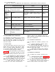
5-56 OVERALL TROUBLESHOOTING PROCEDURE
5-57 To locate the cause of trouble, follow Steps
1, 2, and 3 in sequence:
(1) Check for obvious troubles such as trip-
ped circuit breaker, defective power cord, incor-
rectly strapped rear terminals, input power failure
or defective meter.
Next, remove the top and bot-
tom covers and inspect for open connections,
charred components, etc. , paying particular atten-
tion to both sides of the main circuit board.
(Refer
to Paragraph 5-64 for the main circuit board remov-
al procedure. ) If the trouble source cannot be de-
tected by visual inspection, re-install the main
circuit board and proceed to Step (2).
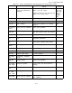
(2) In almost all cases, the trouble can be
caused by incorrect dc bias or reference voltages;
thus, it is a good practice to check the voltages
in Table 5-2 before proceeding with Step (3). Re-
fer to Figure 7-10 for the location of the test points
listed in Table 5-2.
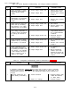
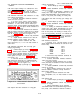
(3) Disconnect load and examine Table 5-3
to determine your symptom and its probable cause.
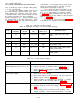
Table 5-2. Reference and Bias Voltages
(Refer to Schematic and Figure 7-10 for test point locations)
STEP
METER
METER
NORMAL
NORMAL
COMMON
POSITIVE
VDC RIPPLE (P-P)
PROBABLE CAUSE
1
+S
TP63
+12.4 ± 7%
2.0mV
CR61, CR62, Q60, Q61, Q62,
Q63
2
+S
TP64
+6.2 ±5%
0.5mV
VR60, VR61, Q62, Q63
3
+S
TP65
-6.2 ±5%
2.0mV
VR60, VR61, Q62, Q63
4
+S
TP66
+11 ±15%
2.0V
C44, CR53, CR54
5
+S
TP67
-4.0 ±12.5%
0.8V
C44, CR53, CR54, CR45, CR46,
CR47, CR48, CR49
6
+S
TP68
-2.4±12.5%
0.4V
CR54, CR45, CR46, CR47,
CR48, CR49
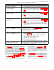
Table 5-3.
Overall Trouble shooting
SYMPTOM
Low or no output voltage
(Overvoltage lamp may be on or off)
High output voltage
High ripple
PROBABLE CAUSE
a.
Front panel meter defective.
b. Crowbar not reset or defective. Refer to Table 5-4.
c.
Series regulator or preregulator feedback loop defective.
Refer to Table 5-4.
a.
Front panel meter defective.
b. Open circuit between sensing terminals (*S) and output ter-
minals (*OUT).
Refer to Table 5-4.
c. Series regulator or preregulator loop defective. If crowbar
does not trip, it also is faulty. Refer to Table 5-4.
a.
Ground loops in operating setup. Refer to Paragraph 5-15.
b. Incorrect reference and\or bias voltages. Refer to Table
5-2.
c. Supply crossing over to constant current operation under
loaded conditions.
Check current limit setting or constant
.
5-10