
user manual

5-81 CONSTANT VOLTAGE PROGRAMMING
CURRENT
5-82 Zero Output Voltage. To calibrate the zero
voltage programming accuracy, proceed as direct-
ed in Paragraphs 5-83, 5-84, 5-85, or 5-86,
whichever applies to your particular instrument.
5-83 Standard instrument with resistance or unity-
gain voltage programming.
a. Connect differential voltmeter between
+OUT and -OUT bus bars.
b. If unit is to be used in local program-
ming mode, turn VOLTAGE controls fully counter-
clockwise. If unit is to be used in remote pro-
gramming mode, connect remote programming setup
(Figure 3-3 or 3-4) and adjust remote resistance or
voltage to zero (minimum).
c.
Connect decade resistance box between
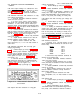
pads of position marked for resistor R110 in “ZERO
ADJUST” section of main circuit board (points “A”
and “B” in Figure 5-10; also see Figure 7-10).
d. Rotate CURRENT controls fully clockwise
and turn on supply.
e. Adjust decade resistance box until dif-
ferential voltmeter reads exactly zero volts.
f. Replace decade resistance box with
fixed, metal film, 1%, 1/4 or 1/8 watt resistor of
same value.
5-84 Standard instrument with non-unity gain
voltage programming.
a.
Perform Steps (a) and (b) in Paragraph
5-83.
b. Solder jumper between “wiper” pad and
“+12.4V” pad of position marked for potentiometer
R112 in “ZERO ADJUST” section of main circuit
board (points “C” and “ D“ in Figure 5-10; also
see Figure 7-10).
c. Connect decade resistance box between
pads marked for resistor R111 in “ZERO ADJUST”
section of main circuit board (points “ E“ and “ F“
in Figure 5-10; also see Figure 7-10).
d. Perform Steps (d) through (f) in Paragraph
5-83.
Figure 5-10. “ZERO ADJUST” Section of Main
circuit Board
5-85 Option 020 with resistance or unity-gain
TM 11-6625-2958-14&P
voltage programming.
a.
Perform Steps (a) and (b) in Paragraph
5-83.
b. Rotate CURRENT controls fully clockwise
and turn on supply.
c. If reading on differential 1 voltmeter is not
exactly zero volts, adjust potentiometer R113 (la-
beled "VOLTAGE ZERO" and accessible through
hole in’ rear panel) until reading is exactly zero.
5-86 Option 020 with non-unity gain voltage pro-
gramming.
a.
Perform Steps (a) and (b) in Paragraph
5-83.
b. Rotate CURRENT controls fully clockwise
and turn on supply.
c. If reading on differential voltmeter is not
exactly zero volts, adjust potentiometer R112 (la-
beled “VOLTAGE PROG” and accessible through
hole in rear panel) until reading is exactly zero.
5-87 CV Programming Accuracy. To caIibrate the
constant voltage programming current, proceed as
directed in Paragraphs 5-88 or 5-89, whichever
applies to your particular instrument.
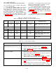
5-88 Standard instrument.
a. Connect 0.1%, 1/8 watt resistor of value
shown below between terminals -S and A3 on rear
barrier strip.
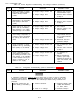
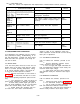
Model
Value
62596
2K Ω
62606
2K Ω
62616
4K Ω
6268B
8K Ω
62696
8K Ω
b. Disconnect strap between terminals Al
and A2 on rear barrier strip.
c. Connect differential voltmeter between
+OUT and -OUT bus bars.
d. Connect decade resistance box in place
of R3 (mounted on standoffs on main circuit board;
see Figure 7-10).
e.
Rotate CURRENT controls fully clockwise
and turn on supply.
f. Adjust decade resistance box until dif-
ferential voltmeter indicates exactly maximum
rated output voltage.
g. Replace decade resistance box with
fixed, composition, 5%, 1/2 watt resistor of same
vaIue.
5-89 Option 020.
a.
Perform Steps (a) through (c) in Paragraph
5-88.
b. Rotate CURRENT controls fully clockwise
and turn on supply.
c. Adjust potentiometer R112 (labeled
“VOLTAGE PROG” and accessible through hole in
rear panel) until differential voltmeter indicates
5-19