
user manual


(2 PLACES)
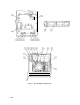
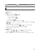
Figure 2.
A6Al
Coaxial Switch and
A6A17
300 MHz BPF Replacement
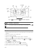
A6A2 RF Attenuator Replacement
Note
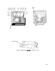
For location of hardware and cables referred to in this procedure, see Figure 3.
Removal
1. Remove front panel from RF Section. (See A5 Front Panel Section for front panel removal
procedure.)
2. Remove top and bottom covers from RF Section.
3. Disconnect attenuator cables
0.
4. Remove two screws
@
used to attach attenuator bracket to motherboard.
5. Remove two screws
@
used to attach attenuator bracket to “totem pole” assembly.
6. Remove RF Module PC board cover by removing six screws
@
and five cables
@
(three
from A6A9 and two from A6A12).
7. Remove A6A9 leaving remaining cables attached.
8. Disconnect attenuator ribbon cable connector
@
from motherboard.
9. Attenuator (attached to bracket) is now free. Remove from RF Module.
10. Remove attenuator bracket from attenuator by removing two screws
0.
4 A6