HP Pavilion dv6 Entertainment PC Maintenance and Service Guide
© Copyright 2008, 2009 Hewlett-Packard Development Company, L.P. Bluetooth is a trademark owned by its proprietor and used by HewlettPackard Company under license. Intel, Celeron, Core, and Pentium are trademarks of Intel Corporation in the U.S. and other countries. Microsoft, Windows, and Windows Vista are U.S. registered trademarks of Microsoft Corporation. SD Logo is a trademark of its proprietor. The information contained herein is subject to change without notice.
Safety warning notice WARNING! To reduce the possibility of heat-related injuries or of overheating the computer, do not place the computer directly on your lap or obstruct the computer air vents. Use the computer only on a hard, flat surface. Do not allow another hard surface, such as an adjoining optional printer, or a soft surface, such as pillows or rugs or clothing, to block airflow.
iv Safety warning notice
Table of contents 1 Product description 2 External component identification Top components ................................................................................................................................... 8 TouchPad ............................................................................................................................ 8 Lights ...................................................................................................................................
Drive handling ................................................................................................... 47 Grounding guidelines ......................................................................................................... 48 Electrostatic discharge damage ........................................................................ 48 Packaging and transporting guidelines ............................................. 49 Workstation guidelines ...............................................
Security menu .................................................................................................................. 106 System Configuration menu ............................................................................................ 106 Diagnostics menu ............................................................................................................ 107 6 Specifications Computer specifications .....................................................................................
9 Connector pin assignments 1394 ................................................................................................................................................. 144 Audio-in (microphone) ...................................................................................................................... 144 Audio-out (headphone) ..................................................................................................................... 145 External monitor .......................
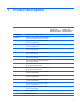
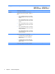
1 Product description Category Description Computer models equipped with graphics subsystems with discrete memory Computer models equipped with graphics subsystems with UMA memory Product Name HP Pavilion dv6 Entertainment PC √ √ Processors Intel® Core™2 Duo T9800 2.93-GHz with 6-MB L2 cache and 1066-MHz front side bus (FSB) √ √ Intel Core2 Duo T9600 2.80-GHz with 6-MB L2 cache and 1066-MHz FSB √ √ Intel Core2 Duo T9550 2.
Category Graphics Description Computer models equipped with graphics subsystems with discrete memory Computer models equipped with graphics subsystems with UMA memory Southbridge: Intel ICH9M √ √ nVIDIA GeForce 9200M GS with 512 MB of dedicated video memory (64 MB × 16 DDR2 × 4 PCs) √ ● Up to 767 MB video memory on computer models equipped with 1 GB of main system memory ● Up to 1279 MB video memory on computer models equipped with 2 GB of main system memory ● Up to 1791 MB video memory on co
Category Description Computer models equipped with graphics subsystems with discrete memory Unified memory architecture (UMA) with shared video memory: Panels Memory Computer models equipped with graphics subsystems with UMA memory √ ● Up to 270 MB of graphics subsystem memory on computer models equipped with 1024 MB of main system memory ● Up to 782 MB of graphics subsystem memory on computer models equipped with 2048 MB of main system memory ● Up to 1294 MB of graphics subsystem memory on comp
Category Hard drives Optical drives 4 Description Computer models equipped with graphics subsystems with discrete memory Computer models equipped with graphics subsystems with UMA memory Supports up to 8 GB system memory √ √ Supports all Serial ATA (SATA) 9.5 mm, 6.35-cm √ (2.5-inch) hard drives √ Supports one hard drive √ √ Support for HP ProtectSmart Hard Drive Protection √ √ Single hard drive configurations: √ √ 12.
Category Description Computer models equipped with graphics subsystems with discrete memory Computer models equipped with graphics subsystems with UMA memory Webcam Low-light VGA camera √ √ Fixed (no tilt) √ √ Activity LED √ √ 640 × 480 by 24 frames per second √ √ Microphone 2 omnidirectional microphones, dual-array with appropriate software (supports beam forming, echo cancellation, and noise suppression) √ √ Audio HD Audio (IDT) √ √ Supports Microsoft® Premium Requirements √ √
Category Description Computer models equipped with graphics subsystems with discrete memory Computer models equipped with graphics subsystems with UMA memory External media card One ExpressCard 54 slot √ √ Digital Media Slot, supports Secure Digital (SD ) √ Memory Card, Multi Media Card (MMC), Memory Stick (MS, Memory Stick Pro (MSP), xD Picture Card (XD) √ Two Mini Card slots √ Internal card expansion Ports ● One slot for WLAN ● One slot for TV tuner or other technologies VGA, 15-pin supp
Category Description Computer models equipped with graphics subsystems with discrete memory 6-cell, 55-Wh, 2.55-Ah Li-ion battery √ 12-cell, 95-Wh, 8.
2 External component identification Top components TouchPad Item Component Description (1) TouchPad light ● White: TouchPad is enabled. ● Amber: TouchPad is disabled. (2) TouchPad* Moves the pointer and selects or activates items on the screen. (3) Left TouchPad button* Functions like the left button on an external mouse. (4) TouchPad on/off button Enables/disables the TouchPad. (5) TouchPad vertical scroll zone Scrolls up or down.
Lights Item Component Description (1) Power lights* (2) ● On: The computer is on. ● Blinking: The computer is in the Sleep state. ● Off: The computer is off or in Hibernation. ● On: A battery is charging. ● Blinking: A battery that is the only available power source has reached a low battery level. When the battery reaches a critical battery level, the battery light begins blinking rapidly.
Item Component Description (11) Stop light On: The stop button has been pressed. (12) Wireless light ● Blue: An integrated wireless device, such as a wireless local area network (WLAN) device and/or a Bluetooth device, is turned on. ● Amber: All wireless devices are turned off. (13) Num lock light On: The integrated numeric keypad is enabled, or num lock is enabled on a connected optional keypad. *The 2 power lights display the same information.
Buttons, speakers and fingerprint reader Item Component Description (1) Speakers (2) Produce sound. (2) Power button* ● When the computer is off, press the button to turn on the computer. ● When the computer is on, press the button briefly to initiate Sleep. ● When the computer is in the Sleep state, press the button briefly to exit Sleep. ● When the computer is in Hibernation, press the button briefly to exit Hibernation.
Item Component Description (7) Next/fast forward button ● Plays the next track or chapter when the button is pressed once. ● Fast forwards media when pressed simultaneously with the fn key. (8) Stop button Stops playback. (9) Wireless button Turns the wireless feature on or off, but does not create a wireless connection. NOTE: A wireless network must be set up in order to establish a wireless connection.
Keys Item Component Description (1) esc key Displays system information about your computer when pressed in combination with the fn key. (2) fn key Executes frequently used system functions when pressed in combination with a function key or the esc key. (3) Windows logo key Displays the Windows Start menu. (4) Windows applications key Displays a shortcut menu for items beneath the pointer. (5) Integrated numeric keypad keys Can be used like the keys on an external numeric keypad.
Front components Item Component Description (1) Power light ● On: The computer is on. ● Blinking: The computer is in the Sleep state. ● Off: The computer is off or in Hibernation. ● On: A battery is charging. ● Blinking: A battery that is the only available power source has reached a low battery level. When the battery reaches a critical battery level, the battery light begins blinking rapidly.
Rear component Component Description Vent Enables airflow to cool internal components. NOTE: The computer fan starts up automatically to cool internal components and prevent overheating. It is normal for the internal fan to cycle on and off during routine operation. Right-side components Item Component Description (1) Optical drive Reads optical discs and, on select models, also writes to optical discs. (2) Optical drive light Blinking: The optical drive is being accessed.
Left-side components Item Component Description (1) External monitor port Connects an external VGA monitor or projector. (2) Expansion port 3 Connects the computer to an optional docking device or an optional expansion product. NOTE: The computer has only one expansion port. The term expansion port 3 describes the type of expansion port. (3) RJ-45 (network) jack Connects a network cable.
Bottom components Item Component Description (1) Hard drive bay Holds the hard drive. (2) Vents (8) Enable airflow to cool internal components. NOTE: The computer fan starts up automatically to cool internal components and prevent overheating. It is normal for the internal fan to cycle on and off during routine operation. (3) Battery bay Holds the battery. (4) Memory module compartment Contains the memory module slots.
Display components 18 Item Component Description (1) Internal display switch Turns off the display and initiates Sleep if the display is closed while the power is on. (2) Internal microphones (2) Record sound. (3) Integrated webcam light On: The integrated webcam is in use. (4) Integrated webcam Records audio and video and captures still photographs.
Wireless antennas (select models only) On select computer models, at least 2 antennas send and receive signals from one or more wireless devices. NOTE: The antennas are not visible from the outside of the computer. For optimal transmission, keep the areas immediately around the antennas free from obstructions. To see wireless regulatory notices, refer to the section of the Regulatory, Safety and Environmental Notices that applies to your country or region. These notices are located in Help and Support.
3 Illustrated parts catalog Service tag When ordering parts or requesting information, provide the computer serial number and model description provided on the service tag. (1) Product name: This is the product name affixed to the front of the computer. (2) Serial number (s/n): This is an alphanumeric identifier that is unique to each product. (3) Part number/Product number (p/n): This number provides specific information about the product's hardware components.
Computer major components Item Description (1) Display assembly (includes wireless antenna transceivers and cables) Spare part number 15.6-inch WXGA BrightView display assembly with webcam and 2 microphones, Onyx 511867-001 15.
Item Description Spare part number 15.6-inch WXGA BrightView display assembly with webcam and 2 microphones, Espresso Black 518776-001 15.6-inch WXGA AntiGlare display assembly with webcam and 2 microphones, Moonlight White 518775-001 15.6-inch WXGA AntiGlare display assembly with webcam and 2 microphones, Espresso Black 518777-001 16.0-inch WXGA BrightView display assembly with webcam and 2 microphones, Onyx 511865-001 16.
Item (4) Description Spare part number Latin America 511885-161 Portugal 511885-131 Russia 511885-251 Saudi Arabia 514115-171 South Korea 514115-AD1 Spain 511885-071 Switzerland 511885-BG1 Taiwan 511885-AB1 Thailand 514115-281 Turkey 511885-141 The United Kingdom 511885-031 The United States 511885-001 Keyboard, Moonlight White (includes keyboard cable) Belgium 517864-A41 The Czech Republic 517864-221 Denmark, Norway, and Sweden 517864-DH1 France 517864-051 French Canada
Item (4) (5) Description Spare part number Turkey 517864-141 The United Kingdom 517864-031 The United States 517864-001 Keyboard, Espresso Black (includes keyboard cable) Belgium 518965-A41 The Czech Republic 518965-221 Denmark, Norway, and Sweden 518966-DH1 France 518965-051 French Canada 518966-121 Germany 518965-041 Greece 518965-DJ1 Hungary 518965-211 International 518965-B31 Israel 518965-BB1 Italy 518965-061 Japan 518966-291 Latin America 518965-161 Portugal 51896
Item (6) Description Spare part number For use only with computer models not equipped with a fingerprint reader, Espresso Black 518789-001 Fingerprint reader board (select models only) Included with the top cover Plastics Kit, includes: 511890-001 ● (7a) Express card slot bezel ● (7b) Memory module cover ● (7c) Hard drive bay cover NOTE: (8) (9) See Plastics Kit on page 34 for more information.
Item (11) Description Spare part number Intel Celeron T1600 1.66-GHz with 1-MB L2 cache and 667-MHz FSB (for use only with computers equipped with UMA graphics memory subsystems) 501894-001 WLAN module: (Bluetooth supported) Intel Wi-Fi Link 5100 802.11a/b/g/n WLAN module for use with computer models in all countries and regions 480985-001 Intel Wi-Fi Link 5100 802.11a/b/g WLAN module for use with computer models in all countries and regions 482957-001 Broadcom 4322 802.
Item Description Spare part number Broadcom BCM4312 802.
Item Description Spare part number Broadcom BCM4312 802.11b/g WLAN module for use only with computer models in Antigua and Barbuda, Barbados, Belize, Canada, the Cayman Islands, Guam, Puerto Rico, Trinidad and Tobago, the U.S. Virgin Islands, and the United States 504664-001 Broadcom BCM4312 802.
Item Description (16) Power connector cable Spare part number NOTE: The power connector cable is available in the Cable Kit, spare part number 512832-001. For more information, see Cable Kit on page 35. (17) (18) (19) Battery 12-cell, 95-Wh, 8.8-Ah Li-ion battery for use with all computer models 511884-001 6-cell, 55-Wh, 2.55-Ah Li-ion battery for use with all computer models 511872-001 6-cell, 55-Wh, 2.55-Ah Li-ion battery for use only with computers for Germany 511872-002 6-cell, 47-Wh, 2.
Item 30 Description Spare part number 400 GB, 5400 rpm 511878-001 500 GB, 5400 rpm 511879-001 Hard Drive Hardware Kit (not illustrated, includes left and right bracket rails, connector cable, Mylar cover with tab, and 4 rubber isolators) 483862-001 Chapter 3 Illustrated parts catalog
Display assembly components The HP Pavilion dv6 Entertainment PC offers two types of display assemblies. Component spare parts are listed in this section for AntiGlare display assemblies and BrightView display assemblies.
BrightView display assembly spare parts Item Description (1) Display bezel (includes logo and display lid switch actuator magnet) For use with computer models equipped with 16-inch displays 512359-001 For use with computer models equipped with 15.
Item Description Spare part number DIsplay enclosure, Espresso Black (includes wireless antenna transceivers and cables and logo LED board and cable) 16-inch 518773-001 Display Rubber Kit (not illustrated, includes display bezel rubber screw covers) 15.
Plastics Kit Item 34 Description Spare part number Plastics Kit 511890-001 (1) ExpressCard slot bezel (2) Hard drive bay cover (includes 2 captive screws, secured by C-clips) (3) Memory module compartment cover (includes 1 captive screw, secured by a C-clip) Chapter 3 Illustrated parts catalog
Cable Kit Item Description Spare part number Cable Kit 512832-001 (1) Fingerprint reader cable (2) Audio/Infrared module cable (3) Modem module cable (includes RJ-11 jack) (4) USB cable (5) Power connector cable TV tuner module cable (not illustrated) Cable Kit 35
Miscellaneous parts Description Spare part number AC adapters 65-W AC adapter 463958-001 90-W AC adapter, PFC 463955-001 90-W AC adapter for use only in Germany 510485-005 Power cords, Black: Argentina 490371-D01 Australia and New Zealand 490371-011 Belgium, Europe, Finland, France, Germany, Greece, the Netherlands, Norway, Portugal, Spain, 490371-021 and Sweden Brazil 490371-201 Canada, French Canada, Latin America, Thailand, and the United States 490371-001 Denmark 490371-081 India 4903
Description Spare part number Headphone, black, with volume control and stereo/mono switch 371693–001 Screw Kit 516498-001 ● Phillips PM2.0×3.0 screw ● Phillips PM2.0×14.0 captive screw ● Phillips PM2.5×3.0 screw ● Phillips PM2.5×4.0 screw ● Phillips PM2.5×5.0 screw ● Phillips PM2.5×5.0 captive screw ● Phillips PM2.5×5.5 captive screw ● Phillips PM2.5×6.5 screw ● Phillips PM3.0×3.
38 Spare part number Description 463955-001 90-W AC adapter, PFC 463958-001 65-W AC adapter 465540-001 Full-function remote control 465541-001 Full-function remote control with teletext 480985-001 Intel Wi-Fi Link 5100 802.
Spare part number Description 490371-021 Power cord for use in Belgium, Europe, Finland, France, Germany, Greece, the Netherlands, Norway, Portugal, Spain, and Sweden 490371-031 Power cord for use in the United Kingdom and Hong Kong 490371-061 Power cord for use in Italy 490371-081 Power cord for use in Denmark 490371-111 Power cord for use in Switzerland 490371-201 Power cord for use in Brazil 490371–291 Power cord for use in Japan 490371-AA1 Power cord for use in the People's Republic of
40 Spare part number Description 504664-002 Broadcom BCM4312 802.
Spare part number Description 511872-002 6-cell, 55-Wh, 2.
42 Spare part number Description 511885-DJ1 Keyboard for use in Greece, Onyx 511887-001 Base enclosure (includes rubber feet) 511888-001 Top cover for use only with computer models not equipped with a fingerprint reader, Onyx (includes TouchPad and TouchPad buttons, and speaker assembly) 511890-001 Plastics Kit (see Plastics Kit on page 34) 511892-001 Audio/infrared board (for use with computer models equipped with UMA graphics subsystem memory) 512357-001 16.
Spare part number Description 513479-001 Display Rubber Kit for 15.6-inch AntiGlare displays (includes display bezel rubber screw covers) 513592-001 Intel Core2 Duo T6400 2.00-GHz with 2-MB L2 cache and 800-MHz FSB 513593-001 Intel Core2 Duo T6600 2.20-GHz processor with 2-MB L2 cache and 800-MHz FSB 513599-001 Intel Pentium Dual-Core T4200 2.
44 Spare part number Description 517864-251 Keyboard for use in Russia, Moonlight White 517864-281 Keyboard for use in Thailand, Moonlight White 517864-291 Keyboard for use in Japan, Moonlight White 517864-A41 Keyboard for use in Belgium, Moonlight White 517864-AB1 Keyboard for use in Taiwan, Moonlight White 517864-AD1 Keyboard for use in South Korea, Moonlight White 518764-B31 Keyboard for use Internationally, Moonlight White 517864-BB1 Keyboard for use in Israel, Moonlight White 517864-
Spare part number Description 518965-031 Keyboard for use in the United Kingdom, Espresso Black 518965-041 Keyboard for use in Germany, Espresso Black 518965-051 Keyboard for use in France, Espresso Black 518965-061 Keyboard for use in Italy, Espresso Black 518965-071 Keyboard for use in Spain, Espresso Black 518965-111 Keyboard for use in Switzerland, Espresso Black 518965-131 Keyboard for use in Portugal, Espresso Black 518965-141 Keyboard for use in Turkey, Espresso Black 518965-161 Ke
4 Removal and replacement procedures Preliminary replacement requirements Tools required You will need the following tools to complete the removal and replacement procedures: ● Magnetic screwdriver ● Phillips P0 and P1 screwdrivers ● Flat-bladed screwdriver Service considerations The following sections include some of the considerations that you must keep in mind during disassembly and assembly procedures.
Cables and connectors CAUTION: When servicing the computer, be sure that cables are placed in their proper locations during the reassembly process. Improper cable placement can damage the computer. Cables must be handled with extreme care to avoid damage. Apply only the tension required to unseat or seat the cables during removal and insertion. Handle cables by the connector whenever possible. In all cases, avoid bending, twisting, or tearing cables.
Grounding guidelines Electrostatic discharge damage Electronic components are sensitive to electrostatic discharge (ESD). Circuitry design and structure determine the degree of sensitivity. Networks built into many integrated circuits provide some protection, but in many cases, ESD contains enough power to alter device parameters or melt silicon junctions. A discharge of static electricity from a finger or other conductor can destroy static-sensitive devices or microcircuitry.
Packaging and transporting guidelines Follow these grounding guidelines when packaging and transporting equipment: ● To avoid hand contact, transport products in static-safe tubes, bags, or boxes. ● Protect ESD-sensitive parts and assemblies with conductive or approved containers or packaging. ● Keep ESD-sensitive parts in their containers until the parts arrive at static-free workstations. ● Place items on a grounded surface before removing items from their containers.
Equipment guidelines Grounding equipment must include either a wrist strap or a foot strap at a grounded workstation. ● When seated, wear a wrist strap connected to a grounded system. Wrist straps are flexible straps with a minimum of one megohm ±10% resistance in the ground cords. To provide proper ground, wear a strap snugly against the skin at all times. On grounded mats with banana-plug connectors, use alligator clips to connect a wrist strap.
Unknown user password If the computer you are servicing has an unknown user password, follow these steps to clear the password. NOTE: These steps also clear CMOS. Before disassembling the computer, follow these steps: 1. Shut down the computer. If you are unsure whether the computer is off or in Hibernation, turn the computer on, and then shut it down through the operating system. 2. Disconnect all external devices connected to the computer. 3.
Component replacement procedures This chapter provides removal and replacement procedures. There are as many as 89 screws, in 10 different sizes, that must be removed, replaced, or loosened when servicing the computer. Make special note of each screw size and location during removal and replacement. Service tag When ordering parts or requesting information, provide the computer serial number and model description provided on the service tag.
Computer feet The computer feet are adhesive-backed rubber pads. The feet are included in the Rubber Feet Kit, spare part number 516499-001. There are 4 rubber feet that attach to the base enclosure in the locations illustrated below.
Battery Description Spare part number 12-cell, 95-Wh, 8.8-Ah Li-ion battery for use with all computer models 511884-001 6-cell, 55-Wh, 2.55-Ah Li-ion battery for use with all computer models 511872-001 6-cell, 55-Wh, 2.55-Ah Li-ion battery for use only with computer for Germany 511872-002 6-cell, 47-Wh, 2.55-Ah Li-ion battery for use with all computer models 511883-001 Before disassembling the computer, follow these steps: 1. Shut down the computer.
Webcam/microphone module NOTE: This section applies only to computer models equipped with BrightView display assemblies. See Display assembly on page 75 for webcam/microphone module removal instructions for computer models equipped with AntiGlare display assemblies. NOTE: If it has been determined that the webcam/microphone module is the component that must be replaced to complete the computer repair, the display assembly does not have to be removed.
4. Release the display bezel top edge (3) from the display enclosure. 5. Release the webcam/microphone module (1) from the display enclosure as far as the webcam/ microphone module cable allows. 6. Disconnect the webcam/microphone module cable (2) from the webcam/microphone module. 7. Remove the webcam/microphone module. Reverse this procedure to install the webcam/microphone module.
Optical drive NOTE: The optical drive spare part kit includes an optical drive bezel and bracket. Description Spare part number Blu-ray ROM DVD±R/RW SuperMulti Double-Layer Drive 511881-001 Blu-ray ROM with LightScribe DVD±R/RW SuperMulti Double-Layer Drive 511882-001 DVD±RW SuperMulti Double-Layer Combo Drive 511880-001 Before removing the optical drive, follow these steps: 1. Shut down the computer.
7. Remove the two Phillips PM2.0×3.0 screws (1) that secure the optical drive bracket to the optical drive. 8. Remove the optical drive bracket (2). Reverse this procedure to reassemble and install the optical drive.
Memory module Description Spare part number DDR2, 800-MHz, PC2-6400, 1-DIMM: 4 GB 511871-001 2 GB 511870-001 1 GB 511869-001 Before removing the memory module, follow these steps: 1. Shut down the computer. If you are unsure whether the computer is off or in Hibernation, turn the computer on, and then shut it down through the operating system. 2. Disconnect all external devices connected to the computer. 3.
NOTE: If necessary, use a non-conductive pointed tool to spread the retaining tabs. 5. Remove the module (2) by pulling it away from the slot at an angle. NOTE: Memory modules are designed with a notch (3) to prevent incorrect insertion into the memory module slot. Reverse this procedure to install a memory module.
TV tuner module NOTE: The TV tuner module spare part kit does not include a TV tuner module cable. The TV tuner module cable is included in the Cable Kit, spare part number 512832-001. NOTE: The TV tuner external antenna cables are available using spare part numbers 482900-001 (with F-PAL jack) and 482900-002 (with PAL jack).
Reverse this procedure to install the TV tuner module. RTC battery NOTE: Removing the RTC battery and leaving it uninstalled for 5 or more minutes causes all passwords and CMOS settings to be cleared. Description Spare part number RTC battery 449729-001 Before removing the RTC battery, follow these steps: 1. Shut down the computer. If you are unsure whether the computer is off or in Hibernation, turn the computer on, and then shut it down through the operating system. 2.
Hard drive NOTE: The hard drive spare part kit includes left and right bracket rails, a connector cable, Mylar cover with tab, and 4 rubber isolators.
64 3. Lift the right side (2) of the hard drive bay cover, swing it up and to the left, and remove the cover(3). The hard drive bay cover is included in the Plastics Kit, spare part number 511890-001. 4. Use the Mylar tab (1) to lift the hard drive up, and then slide it to the left (2) to release it from the hard drive bay. 5. Disconnect the hard drive cable (3) from the system board. 6. Remove the hard drive from the hard drive bay.
7. If it is necessary to replace the hard drive bracket or any of the hard drive bracket components, remove the following: (1) Hard drive connector cable (2) Four rubber isolators (3) Four Phillips PM3.0×3.5 screws that secure the hard drive bracket rails and Mylar cover to the hard drive (4) Left and right hard drive bracket rails with mylar cover tabs Reverse this procedure to reassemble and install the hard drive.
WLAN module 66 Description Spare part number Intel Wi-Fi Link 5100 802.11a/b/g/n WLAN module for use with computer models in all countries and regions (Bluetooth supported) 480985-001 Intel Wi-Fi Link 5100 802.11a/b/g WLAN module for use with computer models in all countries and regions (Bluetooth supported) 482957-001 Broadcom 4322 802.
Description Spare part number Broadcom BCM4312 802.
Description Spare part number Broadcom BCM4312 802.11b/g WLAN module for use only with computer models in Antigua and Barbuda, Barbados, Belize, Canada, the Cayman Islands, Guam, Puerto Rico, Trinidad and Tobago, the U.S. Virgin Islands, and the United States (Bluetooth supported) 504664-001 Broadcom BCM4312 802.
3. Remove the WLAN module (3) by pulling it away from the slot at an angle. NOTE: WLAN modules are designed with a notch (4) to prevent incorrect insertion into the WLAN module slot. Reverse this procedure to install a WLAN module.
Switch cover and keyboard Description Spare part number Switch cover (includes LED board and cable), Onyx 512829-001 Switch cover (includes LED board and cable), Moonlight White 518110-001 Switch cover (includes LED board and cable), Espresso Black 518790-001 Keyboards For a list of all keyboards available for your country or region, see pages 23 to 25. Before removing the switch cover and keyboard, follow these steps: 1. Shut down the computer.
2. Remove the following screws: (1) Two Phillips PM2.5×6.5 screws that secure the switch cover to the computer (2) Three Phillips PM2.5×4.0 screws that secure the switch cover to the computer (these are inside the battery bay) (3) Four Phillips PM2.5×6.5 screws that secure the keyboard to the computer 3. Turn the computer display-side up, with the front toward you. 4. Open the computer as far as possible. 5. Lift the rear edge of the switch cover until it detaches from the computer.
72 6. Move the switch cover back so it rests on the display. 7. Remove the three Phillips PM2.0×3.0 screws that secure the keyboard to the computer. 8. Lift the rear edge (1) of the keyboard . 9. Slide the keyboard (2) back until the keyboard connector on the system board is accessible.
10. Release the zero insertion force (ZIF) connector (1) to which the keyboard cable is connected and disconnect the cable (2) from the system board. 11. Remove the keyboard. 12. Disconnect the power button board cable (1) from the low insertion force (LIF) connector on the system board. 13. Disconnect the LED board cable (2) from the LIF connector on the system board. 14. Remove the switch cover. Reverse this procedure to install the switch cover and keyboard.
Power button board Description Spare part number Power button board (includes cable) 512834-001 Before removing the power button board, follow these steps: 1. Shut down the computer. If you are unsure whether the computer is off or in Hibernation, turn the computer on, and then shut it down through the operating system. 2. Disconnect all external devices connected to the computer. 3.
Display assembly NOTE: The display assembly includes a webcam, 2 microphones, and 2 wireless antenna transceivers and cables. Description Spare part number 15.6-inch WXGA BrightView display assembly, Onyx 511867-001 15.6-inch WXGA BrightView display assembly, Moonlight White 517862-001 15.6-inch WXGA BrightView display assembly, Espresso Black 517866-001 15.6-inch WXGA AntiGlare display assembly, Moonlight White 518775-001 15.6-inch WXGA AntiGlare display assembly, Espresso Black 518777–001 16.
2. Remove the WLAN antenna cables from the clip (3) built into the top cover. CAUTION: Support the display assembly when removing the following screws. Failure to support the display assembly can result in damage to the display assembly and other computer components. 3. Remove the four Phillips PM2.5×6.5 screws (1) that secure the display assembly to the computer. 4. Remove the display assembly (2).
5. If it is necessary to replace the display enclosure or any of the display assembly internal components, remove the following screw covers and screws: a. (1) Four rubber screw covers on the display bezel bottom edge. The display rubber screw covers are included in the Display Rubber Kit, spare part number 513479-001 (15.6-inch displays) or 512361-001 (16.0-inch displays). b. (2) Four Phillips PM2.5×5.0 screws. 6. Turn the display assembly upside down, with the bottom edge toward you. 7.
11. Remove the display inverter cover (2) by lifting it straight up. NOTE: You must remove the display inverter cover to free the antenna cables. 12. Remove the display enclosure. The display enclosure table below identifies the correct part to use for each computer model.
14. Disconnect the webcam/microphone module cable (2) from the webcam/microphone module. 15. Remove the webcam/microphone module. The webcam/microphone module is available using spare part number 512827-001. 16. Release the display inverter (1) as far from the display bezel as the display panel cable and backlight cable allow. 17. Disconnect the backlight cables (2) and display panel cable (3) from the display bezel. 18. Remove the display inverter.
20. Remove the display hinge brackets (2). 21. Remove the two Phillips PM2.5×5.0 screws (1) that secure the display hinge to the display panel. 22. Remove the display hinge (2). The display hinge is available in the Display Hinge Kit, spare part number 513477-001 (16-inch display) or 519209-001 (15.6-inch display). NOTE: Steps 23 through 33 provide display assembly internal component removal information for computer models equipped with BrightView display assemblies.
23. If it is necessary to replace the display bezel or any of the display assembly internal components, remove the following screw covers and screws: (1) Two rubber screw covers on the display bezel bottom edge. The display rubber screw covers are included in the Display Rubber Kit, spare part number 512361-001. (2) Two Phillips PM2.5×6.5 screws. 24.
27. Disconnect the display panel cable (2) and the backlight cable (3) from the display inverter. 28. Remove the display inverter. The display inverter is available using spare part number 488317-001. 29. If it is necessary to replace the display panel, remove the two Phillips PM2.5×5.0 screws (1) from the top corners and the six Phillips PM2.5×5.0 screws (2) from the display hinges.
30. Flex the bottom (1) of the display panel back and release the display hinges. Disconnect the display LED cable (2) from the display panel cable. Remove the display panel (3). Display panels are available using spare part number 511868-001 (16-inch WXGA BrightView display panel) or 512363-001 (15.6-inch WXGA BrightView display panel). 31. If it is necessary to replace the display hinges, remove the two Phillips PM2.0×3.0 screws (1) that secure each display hinge to the display panel. 32.
33. If it is necessary to remove the display panel cable, remove the adhesive reinforcement strip (1) from the display panel cable, and disconnect the display panel cable from the top of the display panel (2). Remove the tape (3) that secures the cable to the display panel. The display panel cable is available using spare part number 512825-001. Reverse this procedure to reassemble and install the display assembly.
Top cover NOTE: The top cover spare part kit includes TouchPad and TouchPad buttons, and speaker assembly.
3. Remove one Phillips PM2.5×4.0 screw (2) that secures the top cover to the computer. This screw is in the battery bay. 4. Turn the computer right-side up, with the front toward you. 5. Disconnect the following cables from the system board: (1) TouchPad cable NOTE: On computer models equipped with a standard display assembly, this cable connects to a ZIF connector on the system board.
6. Remove the five Phillips PM2.5×4.0 screws that secure the top cover to the computer. 7. Lift the rear edge (1) of the top cover until it rests at an angle. 8. Remove the top cover (2) by lifting it straight up. Reverse this procedure to install the top cover.
Bluetooth module NOTE: The Bluetooth module spare part kit does not include a Bluetooth module cable. The Bluetooth module cable is available using spare part number 489822-001. Description Spare part number Bluetooth module 483113-001 Before removing the Bluetooth module, follow these steps: 1. Shut down the computer. If you are unsure whether the computer is off or in Hibernation, turn the computer on, and then shut it down through the operating system. 2.
Modem module NOTE: The modem module spare part kit does not include a modem module cable. The modem module cable is included in the Cable Kit, spare part number 501891-001. See Cable Kit on page 35 for more Cable Kit spare part number information. Description Spare part number Modem module for use in all countries and regions except Australia and New Zealand 461749-001 For use only in Australia and New Zealand 461749-011 Before removing the modem module, follow these steps: 1. Shut down the computer.
3. Lift the modem module (3) straight up to disconnect it from the system board. Reverse this procedure to install the modem module.
Audio/infrared board Description Spare part number Audio/infrared board for use with computer models equipped with discrete graphics memory (includes cable) 512836-001 Audio/infrared board for use with computer models equipped with UMA graphics memory (includes cable) 511892-001 Before removing the audio/infrared board, follow these steps: 1. Shut down the computer.
4. Lift the audio/infrared board (4) straight up to remove it from the base enclosure. Reverse this procedure to install the audio/infrared board. USB board Description Spare part number USB board for use with computer models equipped with graphics subsystems with UMA graphics memory (includes cable) 516497-001 USB board for use with computer models equipped with graphics subsystems with discrete graphics memory (includes cable) 516855-001 Before removing the USB board, follow these steps: 92 1.
Remove the USB board: 1. Disconnect the USB board cable (1) from the LIF connector on the system board. 2. Remove the Phillips PM2.5×6.5 screw (2) that secures the USB board to the base enclosure. 3. Remove the USB board (3) from the base enclosure. Reverse this procedure to install the USB board. Power connector cable NOTE: The power connector cable is available in the Cable Kit, spare part number 501891-001. Before removing the power connector cable, follow these steps: 1.
Remove the power connector cable: 1. Remove the power connector cable (1) from the clips and routing channel built into the base enclosure. 2. Remove the Phillips PM2.5×6.5 screw (2) that secures the power connector and bracket to the base enclosure. 3. Remove the power connector bracket (3). 4. Remove the power connector cable (4). Reverse this procedure to install the power connector cable.
System board NOTE: The system board spare kit includes replacement thermal material.
1. Disconnect the modem module cable (1) from the modem module. 2. Disconnect the following cables from the system board: (2) Audio/infrared board cable NOTE: The audio/infrared board cable connects to a LIF connector on the system board. (3) USB board cable NOTE: The USB board cable connects to a LIF connector on the system board. (4) Power connector cable 3. Remove the Phillips PM2.5×6.5 screw (1) that secures the system board to the base enclosure. 4.
TV tuner module cable NOTE: The TV tuner module cable is available in the Cable Kit, spare part number 512832-001. Before removing the TV tuner module cable, follow these steps: 1. Shut down the computer. If you are unsure whether the computer is off or in Hibernation, turn the computer on, and then shut it down through the operating system. 2. Disconnect all external devices connected to the computer. 3.
Modem module cable NOTE: The modem module cable is available in the Cable Kit, spare part number 512832-001. The modem module cable includes the RJ-11 jack. Before removing the modem module cable, follow these steps: 1. Shut down the computer. If you are unsure whether the computer is off or in Hibernation, turn the computer on, and then shut it down through the operating system. 2. Disconnect all external devices connected to the computer. 3.
Fan/heat sink assembly NOTE: The fan/heat sink assembly spare kit includes replacement thermal material. Description Spare part number For use only with computer models equipped with graphics subsystems with discrete memory 512837-001 For use only with computer models equipped with graphics subsystems with UMA memory 512830-001 For use only with computer models equipped with ATI Mobility Radeon HD4650 graphics subsystems 518435–001 NOTE: To properly ventilate the computer, allow at least a 7.
CAUTION: Remove the screws in the order indicated by the callouts to ensure consistent pressure over the processor board. 4. Loosen the three Phillips PM2.5×5.0 captive screws (5), (6), and (7) that secure the fan/heat sink assembly to the system board. CAUTION: Remove the screws in the order indicated by the callouts to ensure consistent pressure over the processor board. 5. Remove the fan/heat sink assembly (8).
Processor NOTE: The processor spare part kit includes thermal material. Description Spare part number Intel Core2 Duo T9800 2.93 GHz with 6-MB L2 cache and 1066-MHz FSB 507951-001 Intel Core2 Duo T9600 2.80 GHz with 6-MB L2 cache and 1066-MHz FSB 507955-001 Intel Core2 Duo T9550 2.66 GHz with 6-MB L2 cache and 1066-MHz FSB 507953-001 Intel Core2 Duo T9400 2.53 GHz with 6-MB L2 cache and 1066-MHz FSB 507954–001 Intel Core2 Duo T6600 2.
g. System board (see System board on page 95). h. Fan/heat sink assembly (see Fan/heat sink assembly on page 99). 1. Turn the processor locking screw (1) one-half turn counterclockwise until you hear a click. 2. Lift the processor (2) straight up and remove it. NOTE: The gold triangle (3) on the processor must be aligned with the triangle icon (4) embossed on the processor socket when you install the processor. Reverse this procedure to install the processor.
5 Setup Utility WARNING! Only authorized technicians trained by HP must repair this equipment. All troubleshooting and repair procedures are detailed to allow repair at only the subassembly or module level. Because of the complexity of the individual boards and subassemblies, do not attempt to make repairs at the component level or modify any printed wiring board. Improper repairs can create a safety hazard.
Using the Setup Utility Changing the language of the Setup Utility The following procedure explains how to change the language of the Setup Utility. If the Setup Utility is not already running, begin at step 1. If the Setup Utility is already running, begin at step 2. 1. Open the Setup Utility by turning on or restarting the computer. While the “Press the ESC key for Startup Menu” message is displayed in the lower-left corner of the screen, press f10.
Displaying system information The following procedure explains how to display system information in the Setup Utility. If the Setup Utility is not open, begin at step 1. If the Setup Utility is open, begin at step 2. 1. Open the Setup Utility by turning on or restarting the computer. While the “Press the ESC key for Startup Menu” message is displayed in the lower-left corner of the screen, press f10. – or – Open the Setup Utility by turning on or restarting the computer.
After either choice, the computer restarts in Windows. Setup Utility menus The menu tables in this section provide an overview of Setup Utility options. NOTE: Some of the Setup Utility menu items listed in this chapter may not be supported by your computer. Main menu Select To do this System information ● View and change the system time and date. ● View identification information about the computer.
Select To do this Fan Always On Enable/disable Fan Always On. When enabled, the computer fan will always be on. Boot Options Set the following boot options: ● f9 and f10 Delay (sec.)―Set the delay for the f9 and f10 functions of the Setup Utility in intervals of 5 seconds each (0, 5, 10, 15, 20). ● CD-ROM boot―Enable/disable boot from CD-ROM. ● Floppy boot―Enable/disable boot from diskette. ● Internal Network Adapter boot―Enable/disable boot from Internal Network Adapter.
6 Specifications Computer specifications Metric U.S. Width 37.85 cm 14.9 in Depth 25.8 cm 10.12 in Height (front to back) 3.4 to 4.2 cm 1.34 to 1.65 in Weight (with optical drive, hard drive, and battery) 3.14 kg 6.93 lbs Camera adds: 0.009 kg 0.02 lbs Dimensions Input power Operating voltage 18.5 V dc @ 3.5 A - 65 W Operating current 3.5 A or 4.
15.6-inch, WXGA BrightView display specifications Metric U.S. Height 21.0 cm 8.27 in Width 35.9 cm 14.1 in Diagonal 39.5 cm 15.6 in Number of colors Up to 262,000 Contrast ratio 500:1 (typical) Brightness 220 nits (typical) Dimensions Pixel resolution Pitch 0.255 × 0.255 mm Format 1366 × 768 Configuration RGB vertical stripe Backlight Edge lit Character display 80 × 25 Total power consumption 6.
16.0-inch WXGA BrightView display specifications Metric U.S. Height 21.4 cm 8.4 in Width 36.5 cm 14.4 in Diagonal 40.6 cm 16 in Number of colors Up to 262,000 Contrast ratio 600:1 (typical) Brightness 200 nits (typical) Dimensions Pitch resolution Pitch 0.259 × 0.259 mm Format 1366 × 768 Configuration RGB vertical stripe Backlight Edge lit Character display 80 × 25 Total power consumption 4.
15.6-inch WXGA AntiGlare display specifications Metric U.S. Height 21.0 cm 8.27 in Width 35.9 cm 14.1 in Diagonal 39.5 cm 15.6 in Number of colors Up to 262,000 Contrast ratio 500:1 (typical) Brightness 220 nits (typical) Dimensions Pixel resolution Pitch 0.255 × 0.255 mm Format 1366 × 768 Configuration RGB vertical stripe Backlight Edge lit Character display 80 × 25 Total power consumption 6.
16.0-inch WXGA AntiGlare display specifications Metric U.S. Height 21.4 cm 8.4 in Width 36.5 cm 14.4 in Diagonal 40.6 cm 16 in Number of colors Up to 262,000 Contrast ratio 600:1 (typical) Brightness 200 nits (typical) Dimensions Pitch resolution Pitch 0.259 × 0.259 mm Format 1366 × 768 Configuration RGB vertical stripe Backlight Edge lit Character display 80 × 25 Total power consumption 4.
Hard drive specifications 500-GB* 400-GB* 320-GB* 250-GB* 160-GB* Height 9.5 mm 9.5 mm 9.5 mm 9.5 mm 9.
Blu-ray ROM DVD±R/RW SuperMulti Double-Layer Drive specifications Applicable disc Read: Write: BD-ROM, BD-R, BD-RE, CD-DA, CD+ (E)G, CD-MIDI, CDTEXT, CD-ROM, CD-ROM XA, MIXED MODE CD, CD-I, CD-I Bridge (Photo-CD, Video CD), Multisession CD (Photo-CD, CDEXTRA, Portfolio, CD-R, CD-RW), CDR, CD-RW, DVDROM (DVD-5, DVD-9, DVD-10, DVD-18), DVD-R, DVD-RW, DVD+R, DVD+RW, DVD-RAM, HDROM (Single Layer), HD-ROM (Dual Layer), HD DVD-R, HD DVD-R for Dual Layer, HD DVD-RW CD-R and CD-RW DVD+R, DVD+R(9), DVD+RW, DVD-R
DVD±RW and CD-RW SuperMulti Double-Layer Combo Drive specifications Applicable disc Read: Write: BD-ROM, BD-R, BD-RE, CD-DA, CD+(E)G, CDMIDI, CD-TEXT, CD-ROM, CD-ROM XA, MIXED MODE CD, CD-I, CD-I Bridge (Photo-CD, Video CD), Multisession CD (Photo-CD, CD-EXTRA, Portfolio, CD-R, CD-RW), CD-R, CD-RW, DVDROM (DVD-5, DVD-9, DVD-10, DVD-18), DVDR, DVD-RW, DVD+R, DVD+RW, DVD-RAM CD-R and CD-RW Access time CD DVD Random < 175 ms < 230 ms Cache buffer 2 MB DVD+R, DVD+RW, DVD-R, DVDRW, DVD-RAM Data tra
System DMA specifications Hardware DMA System function DMA0 Not applicable DMA1* Not applicable DMA2* Not applicable DMA3 Not applicable DMA4 Direct memory access controller DMA5* Available for ExpressCard DMA6 Not assigned DMA7 Not assigned *ExpressCard controller can use DMA 1, 2, or 5.
System interrupt specifications Hardware IRQ System function IRQ0 System timer IRQ1 Standard 101-/102-Key or Microsoft Natural Keyboard IRQ2 Cascaded IRQ3 Intel 82801 DB/DBM USB2 Enhanced Host Controller—24CD IRQ4 COM1 IRQ5* Conexant AC—Link Audio Intel 82801 DB/DBM SMBus Controller—24C3 Data Fax Modem with SmartCP IRQ6 Diskette drive IRQ7* Parallel port IRQ8 System CMOS/real-time clock IRQ9* Microsoft ACPI-compliant system IRQ10* Intel USB UHCI controller—24C2 Intel 82852/82855 GM/GM
System I/O address specifications I/O address (hex) System function (shipping configuration) 00 - 1F DMA controller Channel 0-3 CF7 PCI Bus on MS ACPI-Compliant System 20 - 21 Programmable Interrupt Controller (Master Controller) 24 - 25 Programmable Interrupt Controller (Aliases) 28 - 29 Programmable Interrupt Controller (Aliases) 2C - 2D Programmable Interrupt Controller (Aliases) 2E - 2F M/B Resource (LPC Controller) 30 - 31 Programmable Interrupt Controller (Aliases) 34 - 35 Programma
I/O address (hex) System function (shipping configuration) BC - BD Programmable Interrupt Controller (Aliases) C0 - DF DMA Controller Channel 4 - 7 F0 Numeric Data Processor 380 - 383 ENE CIR Receiver 384 - 38E EC 3B0 - 3BB VGA 3C0 - 3DF VGA 400 - 47F LPC 4D0 - 4D1 Programmable Interrupt Controlller 500 - 53F LPC 600 - 60F LPC 610 LPC 800 - 80F LPC 810 - 817 LPC 820 - 823 LPC D00 - FFFF PCI Bus on MS ACPI-Compliant System 164E - 164F LPC 2000 - 2FFF ICH9 Family PCI Expre
I/O address (hex) System function (shipping configuration) 8080 - 809F USB UHCI Controller - 2935 80A0 - 80BF USB UHCI Controller - 2934 80C0 - 80DF USB UHCI Controller - 3938 80E0 - 80FF USB UHCI Controller - 2937 8100 - 8117 USB UHCI Controller - 2929 120 Chapter 6 Specifications
System memory map specifications Size Memory address System function 640 KB 00000000-0009FFFF Base memory 128 KB 000A0000-000BFFFF Video memory 48 KB 000C0000-000CBFFF Video BIOS 160 KB 000C8000-000E7FFF Unused 64 KB 000E8000-000FFFFF System BIOS 15 MB 00100000-00FFFFFF Extended memory 58 MB 04800000-07FFFFFF Super extended memory 58 MB 04800000-07FFFFFF Unused 2 MB 08000000-080FFFFF Video memory (direct access) 4 GB 08200000-FFFEFFFF Unused 64 KB FFFF0000-FFFFFFFF System
7 Screw listing This section provides specification and reference information for the screws used in the computer. All screws listed in this section are available in the Screw Kit, spare part number 516498-001, or the Display Screw Kit, spare part number 512362-001.
Phillips PM2.0×3.0 screw Color Quantity Length Thread Head diameter Black 6 3.0 mm 2.0 mm 4.5 mm Where used: One screw that secures the Bluetooth module to the top cover. Where used: Two screws that secure the optical drive bracket to the computer. Phillips PM2.0×3.
Where used: Three screws that secure the keyboard to the computer 124 Chapter 7 Screw listing
Phillips PM2.0×3.0 screw Color Quantity Length Thread Head diameter Silver 8 3.0 mm 2.0 mm 4.5 mm Where used: (1) One screw that secures the WLAN module to the system board (2) One screw that secures the TV tuner module to the system board Phillips PM2.0×3.
Where used: Four screws that secure the display hinge brackets to the display panel.
Phillips PM2.0×14.0 captive screw Color Quantity Length Thread Head diameter Silver 3 14.0 mm 2.0 mm 4.5 mm Where used: Three screws that secure the fan and heat sink to the system board Phillips PM2.0×14.
Phillips PM2.5×3.0 screw Color Quantity Length Thread Head diameter Black 3 3.0 mm 2.5 mm 4.
Phillips PM2.5×4.0 screw Color Quantity Length Thread Head diameter Black 10 4.0 mm 2.5 mm 4.5 mm Where used: One screw that secures the power button board to the switch cover Where used: Three screws that secure the switch cover to the keyboard Phillips PM2.5×4.
Where used: Five screws that secure the top cover to the computer Where used: One screw that secures the top cover to the computer 130 Chapter 7 Screw listing
Phillips PM2.5×5.0 screw Color Quantity Length Thread Head diameter Black 22 5.0 mm 2.5 mm 4.4 mm Where used: Four screws that secure the display inverter cover to the display bezel on computer models equipped with AntiGlare display assemblies Where used: Two screws that secure the display hinge bracket to the display bezel on computer models equipped with AntiGlare display assemblies Phillips PM2.5×5.
Where used: Four screws that secure the display hinges to the display bezel on computer models equipped with AntiGlare display assemblies Where used: Four screws that secure the display enclosure to the display bezel on computer models equipped with AntiGlare display assemblies Where used: Eight screws that secure the display panel to the display on computer models equipped with BrightView display assemblies 132 Chapter 7 Screw listing
Phillips PM2.5×5.0 captive screw Color Quantity Length Thread Head diameter Black 3 5.0 mm 2.5 mm 4.5 mm Where used: Three screws that secure the fan and heat sink to the system board Phillips PM2.5×5.
Phillips PM2.5×5.5 captive screw Color Quantity Length Thread Head diameter Black 6 5.5 mm 2.5 mm 4.
Phillips PM2.5×6.5 screw Color Quantity Length Thread Head diameter Black 25 6.5 mm 2.5 mm 4.4 mm Where used: (1) One screw that secures the USB board to the system board (2) One screw that secures the system board to the computer Where used: Four screws that secure the keyboard to the computer Phillips PM2.5×6.
Where used: Two screws that secure the switch cover to the keyboard Where used: Four screws that secure the display assembly to the computer Where used: One screw that secures the power connector bracket to the base enclosure 136 Chapter 7 Screw listing
Where used: One screw that secures the optical drive to the computer Where used: Nine screws that secure the top cover to the base enclosure Where used: Two screws that secure the display bezel to the display on computer models equipped with BrightView display assemblies Phillips PM2.5×6.
Phillips PM3.0×3.5 screw Color Quantity Length Thread Head diameter Silver 4 3.5 mm 3.0 mm 4.
8 Backup and Recovery Recovering system information Recovery after a system failure is as complete as your most current backup. HP recommends that you create recovery discs immediately after software setup. As you add new software and data files, you should continue to back up your system on a regular basis to maintain a reasonably current backup.
Creating recovery discs NOTE: HP recommends that you create recovery discs to be sure that you can restore your system to its original factory state if you experience serious system failure or instability. Create these discs after setting up the computer for the first time. NOTE: Handle these discs carefully and keep them in a safe place. The software allows the creation of only one set of recovery discs.
Backing up your information When to back up ● On a regularly scheduled basis NOTE: Set reminders to back up your information periodically. ● Before the computer is repaired or restored ● Before you add or modify hardware or software Backup suggestions ● Create a set of recovery discs using Recovery Manager. ● Create system restore points using the Windows System Restore feature, and periodically copy them to disc.
When to create restore points ● Before you add or extensively modify software or hardware ● Periodically, whenever the system is performing optimally NOTE: If you revert to a restore point and then change your mind, you can reverse the restoration. Create a system restore point 1. Select Start > Control Panel > System and Maintenance > System. 2. In the left pane, click System Protection. 3. Click the System Protection tab. 4.
Performing a recovery NOTE: You can recover only files that you have previously backed up. HP recommends that you use Recovery Manager to create an entire drive backup as soon as you set up your computer. Recovery Manager software allows you to repair or restore the system if you experience system failure or instability. Recovery Manager works from recovery discs or from a dedicated recovery partition (select models only) on the hard drive.
9 Connector pin assignments 1394 Pin Signal 1 Power 2 Ground 3 TPB- 4 TPB+ 5 TPA- 6 TPA+ Audio-in (microphone) Pin Signal 1 Audio signal in 2 Audio signal in 3 Ground 144 Chapter 9 Connector pin assignments
Audio-out (headphone) Pin Signal 1 Audio out, left channel 2 Audio out, right channel 3 Ground External monitor Pin Signal 1 Red analog 2 Green analog 3 Blue analog 4 Not connected 5 Ground 6 Ground analog 7 Ground analog 8 Ground analog 9 +5 VDC 10 Ground 11 Monitor detect 12 DDC 2B data 13 Horizontal sync 14 Vertical sync 15 DDC 2B clock Audio-out (headphone) 145
HDMI Pin Signal 1 Transition minimized differential signal (TMDS) data 2+ 2 TMDS data 2 shield 3 TMDS data 2– 4 TMDS data 1+ 5 TMDS data 1 shield 6 TMDS data 1– 7 TMDS data 0+ 8 TMDS data 0 shield 9 TMDS data 0– 10 TMDS clock+ 11 TMDS clock shield 12 TMDS clock- 13 Consumer electric control (CEC) 14 Not connected 15 DDC clock 16 DDC data 17 Ground 18 +5V power 19 Hot plug detect 146 Chapter 9 Connector pin assignments
RJ-11 (modem) Pin Signal 1 Unused 2 Tip 3 Ring 4 Unused 5 Unused 6 Unused RJ-45 (network) Pin Signal 1 Transmit + 2 Transmit - 3 Receive + 4 Unused 5 Unused 6 Receive - 7 Unused 8 Unused RJ-11 (modem) 147
Universal Serial Bus Pin Signal 1 +5 VDC 2 Data - 3 Data + 4 Ground 148 Chapter 9 Connector pin assignments
10 Power cord set requirements The wide range input feature of the computer permits it to operate from any line voltage from 100 to 120 volts AC or from 220 to 240 volts AC. The 3-conductor power cord set included with the computer meets the requirements for use in the country or region where the equipment is purchased. Power cord sets for use in other countries or regions must meet the requirements of the country or region where the computer is used.
Requirements for specific countries or regions Country or region Accredited agency Applicable note number Australia EANSW 1 Austria OVE 1 Belgium CEBC 1 Canada CSA 2 Denmark DEMKO 1 Finland FIMKO 1 France UTE 1 Germany VDE 1 Italy IMQ 1 Japan METI 3 The Netherlands KEMA 1 Norway NEMKO 1 The People's Republic of China CCC 5 South Korea EK 4 Sweden SEMKO 1 Switzerland SEV 1 Taiwan BSMI 4 The United Kingdom BSI 1 The United States UL 2 1.
11 Recycling Battery When a battery has reached the end of its useful life, do not dispose of the battery in general household waste. Follow the local laws and regulations in your area for computer battery disposal. Display WARNING! The backlight contains mercury. Caution must be exercised when removing and handling the backlight to avoid damaging this component and causing exposure to the mercury. CAUTION: The procedures in this chapter can result in damage to display components.
Perform the following steps to disassemble the display assembly: 1. Remove all screw covers (1) and screws (2) that secure the display bezel to the display assembly. 2. Lift up and out on the left and right inside edges (1) and the top and bottom inside edges (2) of the display bezel until the bezel disengages from the display assembly. 3. Remove the display bezel (3).
4. Disconnect all display panel cables (1) from the display inverter and remove the inverter (2). 5. Remove all screws (1) that secure the display panel assembly to the display enclosure. 6. Remove the display panel assembly (2) from the display enclosure. 7. Turn the display panel assembly upside down. 8. Remove all screws that secure the display panel frame to the display panel. 9. Use a sharp-edged tool to cut the tape (1) that secures the sides of the display panel to the display panel frame.
10. Remove the display panel frame (2) from the display panel. 11. Remove the screws (1) that secure the backlight cover to the display panel. 12. Lift the top edge of the backlight cover (2) and swing it outward. 13. Remove the backlight cover. 14. Turn the display panel right-side up.
15. Remove the backlight cables (1) from the clip (2) in the display panel. 16. Turn the display panel upside down. 17. Remove the backlight frame from the display panel. WARNING! The backlight contains mercury. Exercise caution when removing and handling the backlight to avoid damaging this component and causing exposure to the mercury.
18. Remove the backlight from the backlight frame. 19. Disconnect the display cable (1) from the LCD panel. 20. Remove the screws (2) that secure the LCD panel to the display rear panel. 21. Release the LCD panel (3) from the display rear panel. 22. Release the tape (4) that secures the LCD panel to the display rear panel. 23. Remove the LCD panel. 24. Recycle the LCD panel and backlight.
Index Symbols/Numerics 1394 port pin assignments 144 1394 port, identifying 16 1394 Power Saving 106 A AC adapter, spare part numbers 36, 38, 40 administrator password 106 antennas 19 applications key, Windows 13 audio board, spare part numbers 42 audio cable, illustrated 35 audio, product description 5 audio-in (microphone) jack identifying 14 pin assignments 144 audio-out (headphone) jack identifying 14 pin assignments 145 audio/infrared board removal 91 spare part number 28, 42, 91 B backing up customiz
Moonlight White spare part numbers 42, 43, 44, 75 Onyx spare part numbers 40, 75 removal 75 spare part numbers 21, 75 display assembly, Onyx spare part numbers 40 display bezel illustrated 32 release 55 spare part number 32, 42, 81 display cable, spare part numbers 32, 42 display components illustrated 31, 32 recycling 151 display enclosure Espresso Black spare part numbers 31, 44 illustrated 31, 32 Moonlight White spare part numbers 31, 43 removal 77 spare part numbers 32, 42, 78 display enclosure, Onyx sp
hinge illustrated 31, 32 removal 79, 83 spare part numbers 31, 32, 80, 83 I I/O address specifications 118 IEEE 1394 port, identifying 16 infrared lens, identifying 14 integrated webcam, identifying 18 internal microphone, identifying 18 interrupt specifications 117 J jacks audio-in (microphone) 14 audio-out (headphone) 14 RJ-11 (modem) 15 RJ-45 (network) 16 TV antenna/cable 15 K keyboard Espresso Black spare part numbers 44, 45 Moonlight White spare part numbers 43, 44 product description 6 removal 70 spar
network 147 RJ-11 147 RJ-45 147 Universal Serial Bus (USB) 148 plastic parts 46 Plastics Kit contents 34 spare part number 25, 34, 42 play/pause button, identifying 11 play/pause light, identifying 9 pointing device product description 6 ports 1394 16 eSATA/USB 16 expansion 16 external monitor 16 HDMI 16 product description 6 USB 15, 16 power button board removal 74 spare part number 22, 42, 74 power button, identifying 11 power connector cable illustrated 35 removal 93 spare part number 29 power connector,
specifications Blu-ray ROM DVD±R/RW SuperMulti DL Drive 114 computer 108 display 109, 110, 112 DVD±RW Combo Drive 115 hard drive 113 I/O addresses 118 interrupts 117 memory map 121 optical drive 114, 115 system DMA 116 static-shielding materials 50 stop button, identifying 12 stop light, identifying 10 supported discs 140 switch cover Espresso Black spare part number 22 Espresso Black spare part numbers 44 Moonlight White spare part number 22 Moonlight White spare part numbers 44 Onyx spare part numbers 22