
user manual


For more information about installing hardware options and performing
troubleshooting procedures, refer to the p-Class server blade setup and installation
guides on the Documentation CD and to the documentation that ships with the
interconnect switch.
Diagnostic Station Components
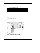
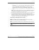
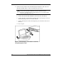
Use Figure 4 and Table 3 to identify diagnostic station components.
Figure 4: Diagnostic station components
Table 3: Diagnostic Station Components
Item Component Description
1 RJ-45 connector for NIC 1 (PXE default and data)
2 RJ-45 connector for NIC 2 (Data)*
3 RJ-45 connector for NIC 3 (Data)*
4 RJ-45 connector for NIC 4 (iLO)
continued
12 HP ProLiant BL p-Class System Diagnostic Station User Guide