
user manual
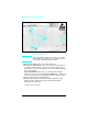
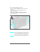
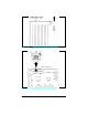

5 Remove the (4) Interface Connector Support Screws from the
rear of the Formatter Cover. The RS-232 connector is held
with 5mm hex-head cap screws (see Figure 6-25b, callout 1).
The parallel connector (see Figure 6-25b, callout 2.) is held in
place with Phillips screws.
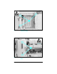
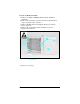
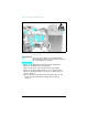
6 Remove the Formatter PCA.
Note When replacing the Formatter Assembly be sure
to reinstall all SIMM modules and MIO cards. Be
sure to reset the page count and the Cold Reset
paper size after replacing the Formatter.
(continued on next page)
Figure 6-25b Interface Connector Support Screws (LaserJet 4)
Removal and Replacement 6-31