
user manual

Fuser Assembly Thermoswitch Removal
Note
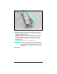
Six of the seven latches are accessed from the top
of the wire cover. These latches are beneath the
felt pad. The slot on the front left side of the wire
harness cover is the best place to begin removing
the cover.
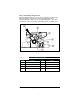
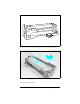
1 Remove the Wire Harness Cover as shown in Figure 6-42a
(LaserJet 4) or Figure 6-42b and c (LaserJet 4 Plus).
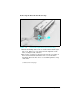
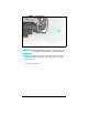
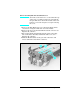
2 Remove the (2) screws from the Thermoswitch connector (see
Figure 6-46, callout 1).
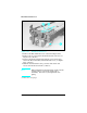
3 Release the thermoswitch latch from the paper sensor flag
side of the Fuser Assembly (behind the side cover). (See
Figure 6-46, callout 2).
4
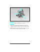
Slide the Thermoswitch to the gear side of the fuser and
release it from the fuser frame (callout 3).
Figure 1-46 Fuser Thermoswitch Connectors
6-55 Removal and Replacement