
user manual

Thermistor Removal
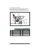
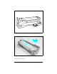
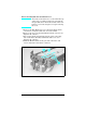
1 Remove the Wire Harness Cover as shown in Figure 6-47.
2 Remove the (2) screws from the thermoswitch connector (see
Figure 6-47, callout 1).
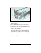
3
Release the thermoswitch latch from the paper sensor flag
side of the Fuser Assembly (behind the side cover, see Figure
6-47, callout 2).
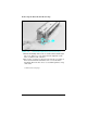
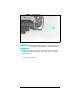
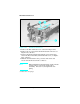
4 Slide the thermoswitch to the gear side of the fuser and
release it from the fuser frame (callout 3).
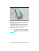
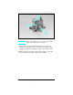
Note
When installing the thermoswitch, make sure the
sensing surface contacts the fusing roller
uniformly. If it does not, straighten the leaf
spring.
(continued on next page)
Figure 1-47 Thermistor Connector
6-56 Removal and Replacement