Service Manual HP OmniBook 2000, 5500, and 5700
Thank you for purchasing this Factory Service Manual CD/DVD from servicemanuals4u.com.
Notice In a continuing effort to improve the quality of our products, technical and environmental information in this document is subject to change without notice. Hewlett-Packard makes no warranty of any kind with regard to this material, including, but not limited to, the implied warranties of merchantability and fitness for a particular purpose.
Table of Contents List of Figures.............................................................................................................................iv List of Tables...............................................................................................................................v Introduction ................................................................................................................................vi Product Overview................................................
Battery (End User Replaceable).............................................................................................64 Memory (End User Replaceable) ...........................................................................................65 Hard Disk Drive (End User Replaceable) ..............................................................................67 Floppy Disk Drive (End User Replaceable) ............................................................................
List of Figures Figure 1 - OmniBook 2000 and 5700 External Features ............................................................11 Figure 2 - OmniBook 2000 and 5700 External Features - continued ..........................................12 Figure 3 - OmniBook 5500 External Features............................................................................13 Figure 4 - OmniBook 5500 External Features - continued..........................................................
List of Tables Table 1 - Additional Resources...................................................................................................vi Table 2 - OmniBook 2000 and 5700 Parts Identification ............................................................16 Table 3 - OmniBook 5500 Parts Identification............................................................................18 Table 4 - POST Beep Codes ...................................................................................................
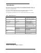
Introduction This document provides reference information for the HP OmniBook 2000, 5500, and 5700. It is intended to be used by HP-qualified service personnel to help with the installation, servicing, and repair of these HP OmniBook PCs. It is a self-paced guide designed to train you to install, configure, and repair the OmniBook Notebook PC. You can follow it without having any equipment available. The following table lists additional sources where supplementary information can be obtained.
vii
Part 1 Product Overview • • • • What’s New Product Features Product at a Glance Product Comparisons
What’s New The OmniBook 2000 is the newest OmniBook in the Desktop-to-Go Notebook PC series. It has many of the same features as the OmniBook 5700 while still maintaining a lower price. The following list compares and contrasts the OmniBook 2000 and OmniBook 5700. Feature Processor OmniBook 2000 133-MHz Intel Pentium with and without MMX technology Cache no L2 cache 16-KB or 32-KB L1 cache Memory Display expandable to 128MB 12.1” TFT SVGA up to 16.7M colors 12.
Product Features The first two illustrations (Figure 1 and Figure 2) point out the key external features of the OmniBook 2000 and 5700. The second two illustrations (Figure 3 and Figure 4) point out the key external features of the OmniBook 5500. Figure 5 on page 14 shows the accessories that can be used in the center bay of the OmniBook 2000, 5500, and 5700.
Kensington lock IR port Serial port VGA out MIDI/Joystick port Kensington lock AC adapter Mouse or Keyboard Docking port Tilt foot Reset button Off button Parallel port Figure 2 - OmniBook 2000 and 5700 External Features - continued 12
Video out IR port Serial port Kensington lock VHS out AC adapter VGA out MIDI/Joystick port Kensington lock Mouse or Keyboard Docking port Parallel port Tilt foot Reset button Latch Figure 3 - OmniBook 5500 External Features Status panel Microphone Pointing device Latch Speaker Display control On/Suspend/Of f button Hard drive Kensington lock Floppy drive Audio jacks (center bay accessory Figure slot) 4 - OmniBook 5500 External Features - continuedPC card slots Battery Speaker 13
PE NT IUM High-capacity battery CD-ROM drive Floppy disk drive Figure 5 - OmniBook 2000, 5500, and 5700 Center Bay Modules Product at a Glance 14
23 4 44 22 28 8 45 5 45 37 43 46 47 40 46 10 18 39 46 30 43 17 46 44 48 6 14 29 37 43 51 32 12 27 26 35 37 9 44 33 18 52 31 19 31 35 20 32 1 35 16 50 43 41 43 38 43 38 7 25 34 36 38 43 15 43 13 37 2 24 38 38 42 44 35 3 11 21 49 Figure 6 - OmniBook 2000 and 5700 Exploded Diagram 15
Table 2 - OmniBook 2000 and 5700 Parts Identification Description Part Number Exchange Part # User Replace.
36 36 36 22 36 36 13 21 40 41 28 41 26 36 40 39 2 42 43 5 15 42 17 17 30 39 42 16 42 44 3 9 29 36 39 34 47 7 27 26 17 32 35 4 40 33 31 18 31 35 19 32 25 35 11 46 39 38 39 37 37 39 24 34 39 10 23 37 1 37 39 40 37 35 8 36 6 20 12 14 45 Figure 7 - OmniBook 5500 Exploded Diagram 17
Table 3 - OmniBook 5500 Parts Identification 1 2 3 4 5 6 7 8 9 10 11 12 13 14 15 16 17 18 19 20 21 22 23 24 25 26 27 28 29 30 31 32 33 34 35 36 37 38 39 40 41 42 43 44 45 46 47 Description Bezel CPU Module CPU Module/100C CPU Module/120C CPU Module/133C Dock Grounding Spring Plate Expansion Door FFC Cable T/B to M/B 10 PIN 3.5" floppy disk drive HDD-FPC Flex Hard Disk Drive HDD Drive 810MB HDD Drive 1.35GB HDD Drive 2.
Product Comparisons HP OmniBook 5700 HP OmniBook 5500 HP OmniBook 2000 Size Closed 29.5 x 22.6 x 4.9 cm (11.6 x 8.9 x 1.93 in) 29.5 x 22.6 x 4.9 cm (11.6 x 8.9 x 1.93 in) 29.5 x 22.6 x 4.9 cm (11.6 x 8.9 x 1.93 in) Weight 3.27 kg (7.2 lb) 3.4 kg (7.5 lb) 3.27 kg (7.
Removable Modules Hard Disk Drive HP OmniBook 5700 HP OmniBook 5500 HP OmniBook 2000 your application or file instantly instantly instantly 2-minute low-battery warning 2-minute low-battery warning 2-minute low-battery warning • Floppy disk drive internal/external (can be replaced with a second battery or CD ROM drive) • Hard disk drive • RAM • Battery 810-MB, 1.35-GB, or 2.
HP OmniBook 5700 HP OmniBook 5500 HP OmniBook 2000 parallel, serial, XGA-out (up to 1024 x 768 x 64k), keyboard, PS/2 mouse, MIDI/joystick, audio and SCSI-2 ports. parallel, serial, XGA-out (up to 1024 x 768 x 256), keyboard, PS/2 mouse, MIDI/joystick, audio and SCSI-2 ports. parallel, serial, XGA-out (up to 1024 x 768 x 64K), keyboard, PS/2 mouse, MIDI/joystick, audio, and SCSI-2 ports.
Part 2 Troubleshooting • • • • • Power-On Self-Test OmniBook Diagnostics Desktop Management Interface System Configuration Utility Troubleshooting Tips
Power-On Self-Test The OmniBook 2000, 5500, and 5700 BIOS includes a Power-On Self-Test (POST) facility that tests a number of hardware and firmware items in the unit at each cold-start (BOOT or RESET). The OmniBook self-test alone should not be used to diagnose a hardware problem. If the selftest results are absolutely clear and repeatable, confirm the results with at least two other nonself-test troubleshooting tools.
Display Codes There are a number of Power On Self Test (POST) tests that are performed after the Beep Code tests. Failure of one or more of these tests will result in a displayed failure code (such as 03044). It is extremely important not to interpret a failure code immediately as a hardware failure. The failure should be confirmed with a clean boot.
Message Possible Cause sequence until you insert the key into the key lock and turn it. NO BOOTABLE FLOPPY DRIVE 0 INSTALLED No bootable floppy drive was detected. Possible solutions: 1) Power down the system and check all appropriate connections, cables, etc. 2) In configurations where no floppy drive is installed, run System Configuration Utility and make sure the diskette drive configuration item is set to "None". 3) Replace the diskette drive if necessary.
OmniBook Diagnostics The OmniBook diagnostics program provides a tool for diagnosing and isolating a hardware problem. The diagnostics software is intended for use in concert with additional troubleshooting methods to accurately determine the cause of trouble. The diagnostics program is not designed for unassisted customer use. Unless otherwise indicated, all diagnostic tests and features are available on the OmniBook 2000, 5500, and 5700.
tests also read the keyboard and discard unexpected key presses, this feature may not work as expected. When looping is enabled (count 0 or greater than 1), the date and time is displayed as each test is executed. The timestamp is displayed as the test begins and is over-written at completion. The DIAG.INI file, located in the c:\omnibook\diag directory, contains a “Loop” entry for each test. The value of the entry determines whether the test can be placed in looping mode as part of a group of tests.
Keys are accepted from the keyboard, an external keyboard, or the serial port. The Alt key, used in conjunction with the appropriate letter, will pop-up each menu on the screen. Refer to Table 6 for a description of each key that is available for use in the user interface. Table 6 - Dianostic Interface Available Keystrokes Space Description run the selected tests (marked or hightlighted) run the alternate selected tests (marked or highlighted). See list of individual tests.
Loop Back Connectors In order to run the RS232 serial port or parallel port self-test, a loop back connector is needed. The loop back may be placed on either the OmniBook port or at the end of the corresponding cable. This feature is also helpful in diagnosing a defective serial or parallel cable. Loop back connectors may be purchased or easily constructed. The following illustrations identify the correct pin-out configurations for the serial and parallel loop back connectors.
Details on Individual Diagnostic Tests This section explains each test within the diagnostics program. Each test is listed along with its command-line file name. A brief description of the test, command-line parameters, valid keystrokes available during the test, and corresponding failure messages with error codes are also given. Note, the term “flushed” that is used in the keystrokes sections indicates that the key is read from the key buffer and then discarded.
CPU - (CPU.EXE) The CPU test checks the general purpose registers by copying a bit pattern through each register. Then a test of the Translation Lookaside Buffer is performed. DOS Parameter none Explanation Valid Keystrokes n/a Action The CPU test ignores the keyboard. Failure Message User Aborted Failed Failed Error Code 1 2 3 Failed 4 Meaning User aborted test. The register test failed. The CPU is in protected mode, must clean boot. The Translate Lookaside Buffer test failed. RAM - (RAM.
Valid Keystrokes n/a Action The ROM test ignores the keyboard. Failure Message User Aborted Error Code 1 Meaning User aborted test. PCMCIA - (PCMCIA.COM) The PCMCIA test sets up the TI CardBus controller chip, tests IRQ 3, and restores the chip. DOS Parameter 0 1 (or any non-0 value) Explanation Test lower slot Test upper slot Valid Keystrokes n/a Action The PCMCIA test ignores the keyboard. Failure Message User Aborted Failed Error Code 1 2 Meaning User aborted test.
Full 2 Unit IR Test - (FIRTEST.EXE) The Full 2 Unit IR test is not available on the OmniBook 5500. This test requires two OmniBooks: one on which the IR is known to be good, and the computer to be tested. The computer that is being tested will transmit IR packets to the known good computer, which will transmit (reflect) the packets back. This method ensures both transmitting and receiving functions are checked on the computer under test. The test checks 115200 baud, 1.
the 3 speeds under test. Default = 3. Limits the test to just one speed which can be set with /BAUD. It also uses all null bytes rather than random data. Default speed = 115200 baud Phytest Valid Keystrokes any key Action Any keystroke will abort The Full 2 Unit IR test. Failure Message OK Must clean boot Explanation The test passed. A clean boot is required prior to the test (see step 1 above). The test was aborted. The test cannot run when the OmniBook is docked.
Printer Port - (LPT.COM) NOTE: This test requires a parallel loopback connector to be connected to the parallel port. The Printer Port test checks the data port by writing and reading different bytes 1000 times. The loopback connector is tested by toggling data bits 0 and 1 and seeing if the PE bit gets set. Finally, all of the loopback connections are tested. DOS Parameter none Explanation Valid Keystrokes n/a Action The Printer Port test ignores the keyboard.
Floppy Disk - (FDC.EXE) NOTE: This test requires a formatted floppy disk to be inserted in the floppy drive. The Floppy Disk test checks for the presence of a floppy drive with a floppy disk. If a floppy disk is not present in the drive, the test will prompt for one. At this point, a floppy disk must be inserted to continue (a reboot is necessary to abort at this stage). The sectors on the floppy disk are then tested. A complete test (100% of the sectors) takes about 1 minute and 38 seconds.
Valid Keystrokes n/a Action The Audio test ignores the keyboard. Failure Message User Aborted Failed Error Code 1 3 Meaning User aborted test. A sound chip configuration call failed Microphone - (MIKE.EXE) Within the user interface of DIAG, the Microphone test records for a short time and then plays back what was recorded (similar to the “Rec” parameter).
Valid Keystrokes Esc Action The Esc key will abort the Joystick test; all other keys are flushed. Failure Message User Aborted Error Code 1 Failed 2 Meaning Pointer movement test aborted with Esc Joystick button test aborted with Esc Icon LCD - (ICON.EXE) The Icon test illuminates each segment of the icons in the icon LCD, moving from left to right. The test then flashes the entire panel three times. This is a visual test; no error codes are returned.
DOS Parameter 1 any non-1 value Explanation Perform the short test Perform the full test Valid Keystrokes any key Action To abort the keyboard test, press five, consecutive, incorrect keys. Failure Message User Aborted Error Code 1 Meaning User aborted test. Pointing Device - (MOUSE.EXE) The Pointing Device test prompts the tester to move the mouse cursor to four points on the display. The left and right mouse buttons are then tested.
other keys flushed. Failure Message User Aborted CD Not Ready H/W Error Drive Not Present Read Error Error Code 1 2 3 4 5 Meaning User aborted test. CD not ready, no CD in drive Timeout waiting for IRQ CD drive not installed The read failed SCSI - (SCSI.EXE) NOTE: The OmniBook must be docked for this test to function properly. The SCSI test checks for the presence of the PCI BIOS and SCSI controller. The test then checks for the presence of a SCSI hard disk, resets it, and copies the file SCSI.
Failure Message User Aborted 44 Error Code 1 Meaning User aborted test.
Desktop Management Interface (DMI) The Desktop Management Task Force (DMTF) was founded in 1992 by a group of leading computer manufacturers, including Hewlett-Packard, to define a standard method of managing the physical and logical components of personal computers. The result of these efforts is the Desktop Management Interface (DMI). The DMI package is pre-installed on the OmniBook 2000 and 5700. Description of DMI DMI is basically a set of rules for accessing information about a personal computer.
The following software is supplied with the DMI package: • A Microsoft Windows utility, SETUP.EXE, to install and initialize the DMI software. • A Windows utility, HP TopTools. After DMI is installed, this utility can be used to display information about the computer through the DMI. • A Management Information Format (MIF) file. This file contains information about everything on the computer that can be controlled using DMI facilities, and is initialized during installation.
Installing the DMI Package from Windows 95 The DMI package is included with the OmniBook, but it must be properly installed before it can be used. The following steps explain how. Alternatively, to install the DMI from floppy disks: • Copy the DMI software from the \omnibook\dirvers\win95\dmi directory of either the hard disk or Recovery CD to two floppy diskettes (copy the contents of the \disk1 subdirectory to diskette #1 and the contents of the \disk2 subdirectory to diskette #2).
System Configuration Utility The System Configuration Utility (SCU) can be used to troubleshoot both software and hardware issues. Settings in the SCU may cause unexpected results in the operation of the OmniBook or installed applications. Battery charge and other system settings also can be verified with the SCU. The SCU settings are identical for the OmniBook 2000, 5500, and 5700, except where noted below.
System Menu The system menu of the SCU provides an interface to modify several system settings. See Figure 13 for an example of the system menu. An explanation of each system setting and the corresponding options are provided in Table 8.
Setting Parameters Default Docking Messages Selected; not selected Not selected Passwords See Figure 14 Passwords Menu Screen on page 50 PC Identification blank Internal Cache Selected; not selected Selected External Cache Selected; not selected Selected Comment changed since previous boot. A change could indicate a virus. Enables warning messages at DOCK and UNDOCK. The text entered here (maximum of 4 lines of 24 characters per line) will be displayed at BOOT time.
Table 9 - Password Menu Settings Setting Passwords… Password option… Admin Password required to: User Password required to: Disable hard disk drive lock2 Set Admin password Set User password Parameters Default Comment Save modifications to PC ID texts Save Setup changes none selected Turn ON, Always; Turn ON, after FN+Suspend; Undock; Save Setup changes none selected Selected; Not selected Not selected. Admin Password is required before proceeding beyond the selected actions.
Table 10 - Disks Menu Settings Setting Disks Floppy Disk Drive Hard Disk Drive Parameters Default None 1.44 Mb 2.88 Mb None Standard Custom Auto-ID 1.44 Mb Auto-ID Comment Select the configuration type of the hard disk. ‘Standard’ selects from a table of older drivers. ‘Custom’ allows manual modification of drive parameters. ‘Auto-ID’ will attempt to automatically type an IDE drive. (This screen also reports # cylinders, # heads, sectors/track, landing zone, write precomp, type code, and size).
Table 11 - Input/Output Menu Settings Setting COM Ports… Serial Port: Parameters Default None COM1, Addr 3F8, IRQ 4 COM2, Addr 2F8, IRQ 3 COM3, Addr 3E8, IRQ 4 COM4, Addr 2E8, IRQ 3 None COM1, Addr 3F8, IRQ 4 COM2, Addr 2F8, IRQ 3 COM3, Addr 3E8, IRQ 4 COM4, Addr 2E8, IRQ 3 COM1, Addr 3F8, IRQ 4 None LPT1, Addr 378 LPT2, Addr 278 LPT3, Addr 3BC LPT1, Addr 378 Standard AT (Centronics) Bidirectional (PS-2) Bidirectional (PS-2) ¼ sec; ½ sec; ¾ sec; 1 sec ½ sec 2 cps; 6 cps; 10 cps; 15 cps; 20 cps; 3
Setting Pointing Device Audio Port… Audio volume Beeper volume: Parameters Default Comment 0-7 0-7 7 3 . Power Menu The power menu of the SCU provides an interface to modify various power management and battery charging configurations3. See Figure 17 for an example of the password menu. An explanation of each power option is provided in Table 12.
Setting Parameters Default HDD power-down Disable/Time (1-30 minutes or never) 3 minutes CPU power-down Disable/Time (512 ms-8 seconds or never) 2 sec Enable hibernate (Save-to-Disk) Timeout during screen activity Selected; not selected Selected Selected; not selected Not selected HDD power-down when on AC Selected; not selected Selected Disable low battery Selected; not selected message2 Battery Charging None Most drained first Least drained first Battery #1 first Battery #2 first Not s
Exit Menu The exit menu of the SCU allows various methods of exiting the interface. See Figure 18 for an example of the exit menu. An explanation of each exit option is provided in Table 13. Figure 18 - Exit Menu Screen Table 13 - Exit Menu Settings Setting Save and Exit Parameters n/a Default n/a Save and Reboot n/a n/a Exit (No Save) n/a n/a Default Settings n/a n/a Restore Settings n/a n/a Version Info… n/a n/a 56 Comment Save current settings and return to previous work.
Troubleshooting Tips Presented below is a table showing general guidelines for repairing units with specific failure symptoms. The order of likely causes is based upon data gathered by HP from analysis of failed modules. The suggested order of investigation is not mandatory but reflects the priority HP would currently place on looking for the root cause. Swapping of easily replaced modules with known good reference modules is the ideal way to isolate the cause down to the module level.
Symptom Keyboard Keyboard errors — 2 characters on a keystroke instead of one Keyboard errors — no response from key(s) Keyboard doesn’t respond, audio slow, battery problems Unit Hangs or Won’t Boot up Won’t boot up & no display Unit hangs at Win95 screen during boot Unit locks up after 2-3 minutes Unit goes into suspend after “Bridge controller” message, won’t resume TrackPoint/Cursor Cursor pointer drifts slightly. Cursor pointer “flying” or drifting excessively.
Symptom Call Center • Send in for repair if still losing time. PCMCIA failure Slow audio and display Computer gets hot • Check device manager in Win95 for resource conflicts • Send in for repair • Send in for repair • It is normal for the computer to get warm/hot especially with 150 & 166 MHz MMX CPU and if charging the battery. Try using the fold down legs to raise the back of the machine to promote air flow. • On OB2000 and OB5700, ensure air vents are clear.
Part 3 Hardware Repair • • • • • • • • • • • • • CAUTION: Battery Memory Hard Disk Drive Floppy Disk Drive Small Parts Display Keyboard Icon Board CPU Module Logic PCA Board Programmable Flash BIOS IC Video Memory Other Components and Accessories Always provide proper grounding when performing any of the following repairs. An electrostatic discharge may cause irreparable damage to the OmniBook and its components.
Battery (End User Replaceable) The OmniBook 2000 and 5700 must use the F1193B (F1193-60902) Standard Lithium Ion battery or the F1194B (F1194-60902) Enhanced Lithium Ion battery. Both of these batteries are fully compatible with the OmniBook 5500. Do not use either the F1193A (F1193-60901) or F1194A (F1194-60901) battery in the OmniBook 2000 or 5700 as data corruption may occur on the hard disk drive. WARNING: Do not mutilate, puncture, or dispose of batteries in fire.
Memory (End User Replaceable) CAUTION: To avoid damage due to electrostatic discharge, handle the memory module by the edges only. The table below lists each of the available memory modules for the OmniBook 2000, 5500, and 5700. The check marks indicate which memory modules are compatible with each OmniBook.
Replacement Procedure 1. Align the memory module over the connector slots and firmly press into place. CAUTION: Avoid pressing the center of the memory module. This action could crack the board. 2. Replace cover and battery(ies) and reset the OmniBook.
Hard Disk Drive (End User Replaceable) Whereas all the hard disk drives are compatible between the OmniBook 2000, 5500, and 5700, the table below indicates which hard drives were originally shipped with each corresponding OmniBook. Table 17 - Hard Drive Availability Matrix Hard Drive Part Number Exchange p/n 810-MB 1.35-GB 2.1-GB 3.1-GB 1.
plastic portion of the hard drive may need to be removed to gain access to the screws of the plastic kit. See Figure 22. 6. Now, the hard drive can be slid out of the case. See Figure 23. Figure 22 - Hard Drive Case Hard Drive Hard Drive Plastic Kit F1350-60920 - OB2000 & OB5700 F1320-60947 - OB5500 only Figure 23 - Removing the Hard Drive Plastic Kit Replacement Procedure 1. Reverse the above Removal Procedure.
Floppy Disk Drive (End User Replaceable) CAUTION: Do not remove the floppy disk drive while the OmniBook is actively reading or writing to it. Wait until the disk is inactive. Required Equipment • none Removal Procedure 1. Slide the release switch on the floppy disk drive to the right. 2. Pull the pull-tab firmly to remove the floppy drive from the compartment. See Figure 24 note, this perspective is with the OmniBook upside down, which is not necessary.
Small Parts (End User Replaceable) The following small parts are all end user replaceable. The procedures are the same for the OmniBook 2000, 5500, and 5700, except where noted. Expansion Door - F1125-60920 Open the door and flex the center of the door until the side-tabs are released. Reverse to replace. Display Contrast/Brightness Slider Button - F1371-60917 Use a blunt probe to gently pry the slider button from the display.
Display (HP Authorized Service Providers Only) The below table summarizes the compatibility of displays between the OmniBook 2000, 5500, and 5700. Please note, that the proper Icon Board must be matched with the corresponding display type and manufacturer. Table 18 - Display Compatibility Matrix Display Part # F1320-69004 F1320-69005 F1320-69006 F1320-69094 F1350-69002 F1371-69006 OB2000 OB5500 OB5700 Icon Board1 PCA PT-ICON PCA PT-ICON PCA PT-ICON2 PCA PB-ICON/SVGA3 12.
Display/Chassis Screws F1081-60939 (qty 2) Figure 25 - Display Screws Figure 26 - Icon Assembly Removal 72
Display Grounding Cable Display Cables Display/Chassis Screws F1081-60939 (qty 2) Display Grounding Cable Figure 27 - Display Cables Replacement Procedure 1. To replace, reverse the above Removal Procedure. Take care to properly position the Display Flex Cable. It must be wrapped three times around the post. See Figure 28. CAUTION: To avoid crimping the icon assembly flex cable, ensure that it is tucked inside of the icon assembly “tunnel.
Display Labels The OmniBook replacement display must be affixed with four labels before it is suitable to return to the customer. The below table summarizes the proper labels for each OmniBook and display type. The illustrations that follow demonstrate the appropriate placement of the Windows 95, Intel, and OmniBook model labels for each of the three display sizes available. Table 19 - Display Label Compatibility Matrix Display Size/Type 12.1” DSTN SVGA 12.1” TFT SVGA 11.3” DSTN SVGA 10.4” TFT SVGA 12.
Windows 95 Label OmniBook Model Label Align top edge with edge of display opening. Intel Label Center vertically between brightness and bottom of display panel. Align with center of Windows 95 label. Figure 30 - 11.3" Display Label Placements Windows 95 Label OmniBook Model Label Intel Label Center vertically between latch opening top edge and rubber bumper bottom edge. Align bottom edge with bottom edge of display opening. Center both labels horizontally in space permitted. Figure 31 - 12.
Keyboard (HP Authorized Service Providers Only) Required Equipment • Small phillips screwdriver Removal Procedure 1. Exit all applications, including Windows. 2. Turn the OmniBook off and remove the battery and ac adapter. 3. Follow the Hard Disk Drive Removal Procedure on page 67 and the Floppy Disk Drive Removal Procedure on page 69 to remove these components. 4.
5. Flex the center of the Palmrest Assembly to release the side-tabs. Disconnect the Keyboard Flex cable. The other two cables can remain in place, or disconnect to fully remove the Palmrest Assembly. 6. Remove the four Keyboard Screws (see Figure 33 for the location of the screws). Keyboard Screws F1320-60920 (qty 4) Figure 33 - Keyboard Screws 7. Lift up the Keyboard – be sure to thread the Keyboard Flex Cable underneath the plastic of the Upper Chassis Case. 8.
DC Power Supply Board F1350-60909 - OB2000 & OB5700 F1320-60925 - OB5500 only Figure 34 - Keyboard Removal 9. Disconnect the two flex cables from the Power Board. Replacement Procedure 1. Reverse the above Removal Procedure. Take note to properly thread the Keyboard Flex Cable underneath the plastic of the Upper Chassis Case.
Icon Board (PCA PB-ICON) (HP Authorized Service Providers Only) The table below lists the icon boards compatible with the OmniBook 2000, 5500, and 5700. Note the column indicating the matching LCD type (the icon boards and LCD types must not be mismatched). There are no exchange part numbers for any of the icon boards.
Upper Chassis Case Screw F1320-60963 Microphone Cable On/Suspend Button Cable Upper Chassis Case F1350-60915 - OB2000 & OB5700 F1320-60931 - OB5500 only Figure 35 - Upper Chassis Case Removal 5. Remove the Icon Board Screw (see Figure 36). Gently rock the Icon Board back and forth to free it from the connector.
Icon Board Screw F1320-60963 Icon Board Figure 36 - Icon Board Removal Replacement Procedure 1. Reverse the above Removal Procedure.
CPU Module (HP Authorized Service Providers Only) The following table lists the various CPU modules for the OmniBook 2000, 5500, and 5700.
CPU Screws F1350-60927 (qty 2) CPU Fan F1350-60906 CPU Module CPU Fan Screw F1350-60925 CPU Fan Screw F1350-60926 Figure 37 - CPU and CPU Fan Removal (OB2000 & OB5700 only) 83
Heat Pipe Bracket Screw F1320-60963 Heat Pipe Bracket F1320-60972 Heat Spreader Screw (left) F1081-60942 CPU Screws (4) F1320-60963 Heat Spreader Screw (right) F1320-60963 Heat Spreader F1320-60921 CPU Module Heat Pipe F1320-60964 Heat Sink F1320-60954 Figure 38 - CPU and Heat Spreader Removal (OB5500 only) Replacement Procedure 1.
Logic PCA Board (PCA PB-586/IO Bracket) (HP Authorized Service Providers Only) The OmniBook 2000 and 5700 are shipped with an electronic serial number programmed in EEPROM on the Logic PCA Board. This built-in serial number will help MIS managers in tracking assets and software configuration. Serial numbers can also be used for security and in tracking lost or stolen notebooks.
The following table summarizes the different logic PCA boards for the OmniBook 2000, 5500, and 5700. Table 22 - Logic PCA Compatibility Matrix Logic PCA PCA PT-586 with I/O Bracket PCA PB-586 with I/O Bracket Part Number F1320-60926 Exchange Part # F1320-69026 F1350-60901 F1350-69001 OB2000 OB5500 OB5700 Required Equipment • Small phillips screwdriver • 5mm hexdriver Removal Procedure 1. Exit all applications, including Windows. 2. Turn the OmniBook off and remove the battery, ac adapter.
5. To remove the Logic PCA Board from the Lower Chassis Case, three screws, two standoffs, the FFC Cable T/B to M/B, and the HDD-FPC Flex must first be removed. See Figure 41 on page 88 for the location of these components. The IR Lens and Bezel are now accessible. CAUTION: Keyboard Shielding Plate Screws (qty 5) F1350-60924 Apply even pressure to both sides of the HDD FPC Flex when removing or replacing to avoid damage to the connector pins on the Logic PCA.
Screw F1350-60924 Standoff F1350-60928 FFC Cable T/B to M/B F1320-60950 Screw F1350-60924 Dock Grounding Spring Plate F1320-60962 Standoff F1350-60929 HDD to FPC Flex F1320-60961 and Bracket F1320-60965 Screw F1350-60924 Logic PCA Board IR Lens F1320-60952 Lower Chassis Case Figure 41 - Logic PCA Board Removal Replacement Procedure 1. Reverse the above Removal Procedure.
Programmable Flash BIOS IC (HP Authorized Service Providers Only) The replacement BIOS IC will contain enough basic BIOS programming to boot the OmniBook. However, after replacing the IC, the BIOS must be reprogrammed. Hewlett-Packard prefers that the system is programmed with the latest BIOS for the respective OmniBook. The latest BIOS can be downloaded from the WWW (see Table 1 - Additional Resources on page vi).
4. Use a BIOS Insertion/Removal Tool to extract the BIOS IC from the Logic PCA. See Figure 43 on page 90. BIOS Insertion/Removal Tool F1371-60904 Programmable Flash BIOS IC F1321-60907 (OB5500 only) F1371-60903 (OB2000 & OB5700) Figure 43 - Flash BIOS IC Removal Replacement Procedure 1. Align the Flash BIOS IC with the slot on the Logic PCA. The IC is keyed to fit correctly. 2. Press down firmly on the IC to ensure a proper connection. See Figure 44. 3. Replace the remainder of the OmniBook components.
Video Memory (OB2000 & OB5700 Only) (HP Authorized Service Providers Only) NOTE: Only the OmniBook 2000 and 5700 contain video memory that is replaceable. This repair procedure is not applicable for the OmniBook 5500. Also be aware that the Video Memory Board contains only 1MB of the total 2MB of video RAM on the system. The other 1MB of video RAM is integrated with the Logic PCA Board.
1. Reverse the above Removal Procedure.
Other Components and Accessories (HP Authorized Service Providers Only) The below table lists additional replaceable components and the disassembly procedure(s) necessary to gain access to each. The accessories require a unit exchange (no repairable parts), unless otherwise indicated.
Component I/O Bracket Grounding Clips Disassembly Procedure(s)/page# Logic PCA Board page 85 Icon Assembly Display - page 71 IR Lens Logic PCA Board page 85 Keyboard Shielding Plate Display - page 71 Keyboard - page 74 Lower Chassis Case Logic PCA Board page 85 Palmrest Assembly Keyboard - page 74 Equipment Special Notes Small phillips screwdriver, 5mm hexdriver Small phillips screwdriver Small phillips screwdriver, 5mm hexdriver Small phillips screwdriver The Clips easily slide off either si
Appendix A - Technical Specifications Mass Storage Specifications Hard Disk Drive The hard disk drive can be removed by the user for easy upgrades. Hard drive manufacturers are subject to change without notice. Table 24 - Hard Disk Drive Specifications 810-million-byte Average access (read) Track to track seek Full Track Average latency Rotational speed Media Transfer rate 13 ms 1.35-billion-byte 1.
Floppy Disk Drive The floppy disk drive can either be placed in the center bay slot or connected to the parallel port. It is hot-swappable and is configured as drive A by default. Floppy disk drive manufacturers are subject to change without notice.
System Resources Below are default values for system resources. To see other, non-default possibilities, use the System Configuration Utility (SCU) which lists port and audio device configurations in the Input/Output menu. For additional information on configuring system resources, refer to the System Configuration Utility section on page 48. The tables in this section show typical resource usage as set up by the OmniBook BIOS.
15 Internal CD-ROM (secondary IDE controller, free if no internal CD) System Memory The following tables list the memory maps for the OmniBook 2000, 5500, and 5700.
Table 32 - System I/O Addresses for the OmniBook 5500 170-178 1F0-1F7 220-22F 2F8-2FF 330-331 378-37A 388 3C0-3DF 3E0-3E1 3F0-3F5 3F6 3F8-3FF 3000-33FF 3400-347F 3E0H-3E1H Secondary HDD controller (internal CD-ROM) Internal hard disk Crystal sound COM2 (infrared port) MPU 401 (MIDI) LPT1 (printer port) Sound VGA adapter PC card bridge on PCI Floppy controller Primary HDD controller COM1 (serial port) VGA on PCI SCSI on PCI PC Card on ISA DMA Channels The following tables lists the available DMA channels f
Appendix B - Hewlett-Packard Password Removal Policy If the user forgets the system password, there is a master password that will unlock the OmniBook. The user calls Technical Support to determine this master password as follows: 1. Support will tell the user the keys to type at the password entry screen: [alt][shft][f10] 2. The OmniBook generates and displays an encoded master password. This is displayed under the normal password entry area.
law enforcement agencies. If you receive such a request, you should notify management and HP Corporate Legal immediately. (These requests may require a court order prior to our participation.) Further, you must log the name, serial number and date of the running of the descramble program, and file the written backup with the log. The log and backup are subject to standard record retention process and review.
Appendix C - Hewlett-Packard TFT Display Quality Statement TFT display manufacturing is a high precision but imperfect technology and manufacturers cannot currently produce large displays that are cosmetically perfect. Most, if not all, TFT displays will exhibit some level of cosmetic imperfection. These cosmetic imperfections may be visible to the customer under varying display conditions and can appear as bright, dim or dark spots.
Appendix D - Assembly Sub-Component Breakout The following pages contain a breakout of various sub-components of the major replaceable assemblies for the OmniBook 2000, 5500, and 5700. The chart indicates whether or not the subcomponent is included with the replacement assembly. For example, a replacement hard disk drive does not include a hard drive plastic kit. The plastic kit from the defective hard drive may be reused or a new plastic kit may be ordered separately.
Assembly LCD Assy - 11.3” DSTN/S LCD Assy - 12.1” TFT/S 1 OmniBook Sub-component(s) 200 550 570 0 0 0 F1320-60905 F1320-60906 Display Label 5500CT Label - Intel Pentium Label - Win95 Top Rubber Pad (2) Bottom Rubber Pad (2) Disp Panel Plastic 11.3” DSTN Disp Cover Plastic 11.3” DSTN Display Hook- Left Display Hook Right Display Hook Button (2) Display Contrast Btn (2) Flex Cable 11.
Assembly LCD Assy /SMG 12.1” TFT/S LCD Assy 12.1” DSTN LCD Assy 12.1” 2 OmniBook Sub-component(s) 200 550 570 0 0 0 F1320-60994 F1371-60906 F1350-60902 Label - Win95 Top Rubber Pad (2) Bottom Rubber Pad (2) Disp Panel Plastic /SMG 12.1” TFT Disp Cover Plastic /SMG 12.1” TFT Display Hook- Left Display Hook Right Display Hook Button (2) Display Contrast Btn (1) Flex Cable 12.
Assembly OmniBook Sub-component(s) 200 550 570 0 0 0 TFT/X 12.1” TFT Disp Cover Plastic 12.1” TFT Display Hook- Left Display Hook Right Display Hook Button (2) Display Contrast Btn (1) Cable 12.1” XGA Label - HP OmniBook Display Label 5700CTX Label - Intel MMX Label - Win95 Top Rubber Pad (2) Bottom Rubber Pad (2) Display Panel Plastic Display Panel F1320-60932 Plastic 12.1” TFT Display Panel F1320-60934 Plastic 10.4” TFT Display Panel Plastic 11.
Assembly Display Panel Plastic/ SMG 12.1” TFT Display Panel Plastic 12.
Assembly OmniBook Sub-component(s) 200 550 570 0 0 0 HDD Drive F1192-60901 1.35GB HDD Drive F1375-60901 1.44GB HDD Drive 2.1GB F1339-60901 HDD Drive 3.
Assembly OmniBook Sub-component(s) 200 550 570 0 0 0 F1081-60946 Microphone Palmrest Assembly F1320-60986 PCA PT-586 PCA-PT-586 w/IO F1320-60926 Bracket PCA-PB-586 w/IO F1350-60901 Bracket Upper Chassis Case Upper Chassis F1320-60931 Case Upper Chassis Case 4 F1350-60915 Overlay/Regulatory Memory Cover Door Printer Port Door Expansion Door I/O Door Door, Flash BIOS Bezel IR Lens Rubber Gasket TrackPoint Btns (2) TrackPoint PCB Speakers (2) Sub-battery Included (y/n) F1320-60927 No F1125-60918 F112
Assembly OmniBook Sub-component(s) 200 550 570 0 0 0 Sub Battery NiMH Suspend/Resume Btn Icon Assembly Keyboard Palmrest Assembly 110 Included (y/n) F1350-60921 No n/a Yes F1320-60918 No see footnote3 No F1320-60986 No
Appendix E - Part Numbers Part Number Exchange Part Number 5182-5113 5183-2257 5183-2258 5965-0241 5965-0262 7121-7353 7121-7455 F1065-80005 F1065-80017 F1081-60925 F1081-60939 F1081-60942 F1081-60946 F1125-60918 F1125-60920 F1125-60925 F1125-60929 F1134-60901 F1134-69001 F1135-60901 F1135-69001 F1136-60901 F1136-69001 F1189-90008 F1191-60901 F1192-60901 F1193-60902 F1194-60902 F1195-60901 F1320-40001 F1320-60901 F1320-60902 F1320-60903 F1320-60904 F1320-60905 F1191-69001 F1192-69001 F1320-69001 F1320-69
Part Number Exchange Part Number F1320-60921 F1320-60924 F1320-60925 F1320-60926 F1320-69026 F1320-60927 F1320-60928 F1320-60929 F1320-60930 F1320-60931 F1320-60932 F1320-60933 F1320-60934 F1320-60935 F1320-60936 F1320-60937 F1320-60938 F1320-60939 F1320-60940 F1320-60941 F1320-60942 F1320-60943 F1320-60947 F1320-60948 F1320-60949 F1320-60950 F1320-60951 F1320-60952 F1320-60954 F1320-60955 F1320-60957 F1320-60958 F1320-60960 F1320-60961 F1320-60962 F1320-60963 F1320-60964 F1320-60965 F1320-60966 112 Descr
Part Number Exchange Part Number F1320-60967 F1320-60968 F1320-60969 F1320-60970 F1320-60971 F1320-60972 F1320-60973 F1320-60974 F1320-60975 F1320-60976 F1320-60977 F1320-60978 F1320-60979 F1320-60980 F1320-60981 F1320-60982 F1320-60983 F1320-60984 F1320-60985 F1320-60986 F1320-60988 F1320-60989 F1320-60990 F1320-60991 F1320-60993 F1320-60994 F1320-69094 F1320-60995 F1320-60996 F1320-60997 F1321-60901 F1321-60902 F1321-60903 F1321-60904 F1321-60905 Description Thermal Tape PT-586 F65548 Screw ISOFS M3X
Part Number Exchange Part Number F1321-60906 F1321-60907 F1335-60901 F1335-69001 F1336-60901 F1336-69001 F1338-60901 F1339-60901 F1347-60901 F1348-60901 F1349-60901 F1339-69001 F1347-69001 F1348-69001 F1349-69001 F1350-60901 F1350-60902 F1350-60904 F1350-60905 F1350-60906 F1350-60907 F1350-60908 F1350-60909 F1350-60910 F1350-60911 F1350-60912 F1350-69001 F1350-69002 F1350-69004 F1350-69005 F1350-60913 F1350-60914 F1350-60915 F1350-60916 F1350-60917 F1350-60918 F1350-60919 F1350-60920 F1350-60921 F1350-
Part Number Exchange Part Number F1350-60934 F1350-60935 F1350-60936 F1350-90001 F1350-90002 F1350-90003 F1350-90016 F1371-60901 F1371-60902 F1371-60903 F1371-60904 F1371-60905 F1371-60906 F1371-69006 F1371-60908 F1371-69008 F1371-60909 F1371-69009 F1371-60911 F1371-60912 F1371-60913 F1371-60914 F1371-60915 F1371-60916 F1371-60917 F1375-60901 F1375-69001 Description Recovery Kit SPA Recovery Kit SWE OmniBook 5700 Training Video Setup Guide OB5700 English Setup Guide OB5700 E,F,I,G,S,P Setup Guide OB5700 E,
HP Part Number 5965-0262