
Manual
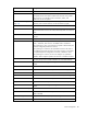
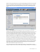
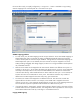
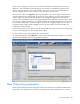
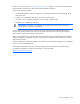
Table Of Contents
- HP Virtual Connect for c-Class BladeSystemVersion 3.01User Guide
- Notice
- Contents
- Introduction
- Overview
- HP Virtual Connect Manager
- Domain management
- Domain overview
- Firmware updates
- Domain Settings (Domain Configuration) screen
- Domain Settings (Domain IP Address) screen
- Domain Settings (Domain Enclosures) screen
- Domain Settings (Backup/Restore) screen
- Domain Settings (Local Users) screen
- Directory Settings (Directory Server) screen
- Directory Settings (Directory Groups) screen
- Directory Settings (Directory Certificate) screen
- Test LDAP authentication
- SNMP overview
- System Log screen
- System Log Configuration
- Network management
- Networks overview
- Define Ethernet Network screen
- Edit Ethernet Network screen
- Ethernet Networks (External Connections) screen
- Ethernet Networks (Server Connections) screen
- Ethernet Settings (MAC Addresses) screen
- Ethernet Settings (Port Monitoring) screen
- Ethernet Settings (Advanced Settings) screen
- Stacking Links screen
- Shared uplink sets and VLAN tagging
- Define Shared Uplink Set screen
- Shared Uplink Sets (External Connections) screen
- Shared Uplink Sets (Associated Networks) screen
- Storage management
- Server management
- Certificate Administration
- Hardware information screens
- Enclosure Information screen
- Enclosure Status screen
- Interconnect Bays Status and Summary screen
- Causes for INCOMPATIBLE status
- Interconnect Bay Summary screen (Ethernet module)
- Interconnect Bay Summary screen (VC-FC Module)
- Module removal and replacement
- Interconnect Bay Overall Status icon definitions
- Interconnect Bay OA Reported Status icon definitions
- Interconnect Bay VC Status icon definitions
- Interconnect Bay OA Communication Status icon definitions
- Server Bays Summary screen
- Server Bay Status screen
- Acronyms and abbreviations
- Glossary
- Index
Server management 106
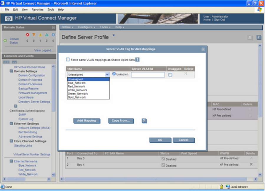
the server side. Finally, to simplify configuration, a "Copy From…" button is available to copy existing
network mappings from a shared uplink set or from other server ports.
VLAN ID mapping guidelines
• For each server port, all VLAN mappings must be unique. When the 'Force same VLAN mappings as
Shared Uplink Sets' option is selected, this setting is handled automatically because all networks
within a shared uplink set must have unique VLAN IDs. If the global 'Force same VLAN mappings as
Shared Uplink Sets' option is not selected, then each network can only be mapped to one server
VLAN (including untagged). After being mapped, a network is no longer available in the drop-down
list of available networks.
• Different server VLANs can be mapped to the same network between two different server ports. For
example, in server port 1, server VLAN 100 maps to the Purple network. In port 2, server VLAN 200
also maps to the Purple network. The result is that these different server VLANs can communicate
with each other directly, and a broadcast frame on VLAN 100 from server port 1 is sent into the VC
Domain and comes out to VLAN 200 on server port 2. This behavior extends to any number of
different server VLANs mapped to the same vNet in any given VC Domain.
• The same server VLAN can be mapped to two different networks. This action has a similar but
opposite effect to the above scenario. For example, server VLAN 300 is mapped to the Green
network on server port 1, but mapped to the Red network on server port 2. This mapping means that
server VLAN 300 is split into separate broadcast domains for different server ports.
• If an external VLAN is "Unassigned," packets with that tag are dropped, which is the same as if that
external VLAN was never specified. However, this setting allows users to pre-define or reserve a spot
for that VLAN and activate it later by connecting it to a VC Ethernet network.
Copying VLAN mappings