
Maintenance and Service Guide


Heat sink assembly
Table 6-15 Heat sink assembly descriptions and part numbers
Description Spare part number
Heat sink for use in models with discrete graphics L22531-001
Heat sink for use in models with integrated UMA graphics L22530-001
Heat plate for use in fanless models L22532-001
Before removing the heat sink, follow these steps:
1. Prepare the computer for disassembly (Preparation for disassembly on page 32).
2. Remove the optical drive (see Optical drive on page 33).
3. Remove the bottom cover (see Bottom cover on page 37).
4. Remove the battery (see Battery on page 40).
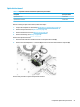
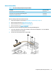
To remove the heat sink assembly from products with integrated UMA graphics:
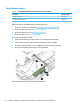
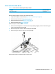
1. In the order indicated on the heat sink assembly, remove the four Phillips M2.0 × 3.0 screws (1) that
secure the heat sink to the computer.
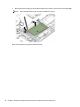
2. Lift the heat sink assembly from the computer (2).
Component replacement procedures 57