Perforate HP Customer Support Services How to get the latest software/firmware You can download any of the following: HP AdvanceStack SNMP firmware: HP Interconnect Manager: HP Stack Manager asfw.exe icmupdt.exe stkmgr.exe from the World Wide Web, HP BBS, HP FTP Library Service, and CompuServe. After you download the file, exact the file file by typing filename /x. For example asfw.exe /x World Wide Web http://www.hp.com/go/network_city HP BBS With your telecommunication program (e.g.
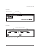
HP AdvanceStack Redundant Power Supply Installation and Reference Guide
©Copyright Hewlett-Packard Company 1995, 1998. All Rights Reserved. Reproduction, adaptation, or translation without prior written permission is prohibited, except as allowed under the copyright laws. Publication Number J2962-90001 April 1998 Printed in Singapore. Applicable Product HP J2962A Trademark Credits MS-DOS® and Microsoft® are U.S. registered trademarks of Microsoft Corporation. Ethernet is a registered trademark of Xerox Corporation.
Table of Contents Table of Contents At a Glance . . . . . . . . . . . . . . . . . . . . . . . . . . . . . . . . 2 Features . . . . . . . . . . . . . . . . . . . . . . . . . . . . . . . . . . 2 Front of the RPS . . . . . . . . . . . . . . . . . . . . . . . . . . . . . 3 Back of the RPS . . . . . . . . . . . . . . . . . . . . . . . . . . . . . . 3 Installation Summary . . . . . . . . . . . . . . Included Parts . . . . . . . . . . . . . . . . 1. Mount the RPS . . . . . . . . . . . . . . . 2.
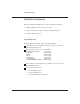
HP Redundant Power Supply HP Redundant Power Supply At A Glance The HP J2962A Redundant Power Supply (hereafter RPS) provides redundant DC power to HP products that contain a redundant power supply connector. Features Network Connections Provides fully redundant power to four devices. Modular, Easy-to-Use Design Nine LEDs to provide power, connectivity, and diagnostic information about the RPS. Also, each supported device has an RPS LED to report the status of the Redundant Power Supply.
HP Redundant Power Supply Front of the RPS LED Troubleshooting Key RPS status LEDs Back of the RPS DC power receptacles for four devices Two AC power receptacles 3
Installation Summary Installation Summary The basic hardware installation procedure for the RPS is as follows: 1. Mount the RPS in a rack or place it on a table. 2. Connect the RPS to the devices that need redundant power. 3. Verify the RPS’s operation.
Installation Summary 1. Mount the RPS For safe and reliable operation, the RPS can be placed on a table or mounted in a rack or cabinet only. Hewlett-Packard sells 19-inch free-standing equipment racks. To order a rack for your RPS and hubs, call HP at 1-800-538-8787 and request part number 46298D. Mounting Precautions Before mounting an RPS, plan its location and orientation relative to other devices and equipment. Also consider the cabling that will be attached to the RPS and ports that will be used.
Installation Summary Rack Mounting Warning The rack or cabinet should be adequately secured to prevent it from becoming unstable and/or falling over. 1. Using a Phillips (cross-head) screwdriver, attach the mounting brackets to the RPS with the 10-mm M4 screws included in the accessory kit (5063-8522). The top of each bracket should align with the top of the RPS. Be careful not to overtighten the screws. 2.
Installation Summary If you are stacking hubs and the RPS in a single rack and want them to fit tightly, the selection of the first screw holes is important. In a standard 19-inch telco rack, the screw hole pattern has repetitive pairs of holes separated by 0.5-inch or 0.625-inch. Insert these first screws in the upper hole of a close (0.5-inch) pair, as shown in the illustration. Insert a screw into the top hole of a close (0.5inch) pair—like one of these—one in each of the rack uprights.
Installation Summary 2. Connect the RPS to Supported Devices To connect the RPS to one or more devices, follow these steps: 1. Select up to four devices that need redundant power, for example, the HP J2601B AdvanceStack 10Base-T Hub-24 or the HP J2602B AdvanceStack 10Base-T Hub-48. 2. Notify the users on these devices that the network will be down temporarily. 3. Disconnect the AC power cord from the selected device and store the AC power cord. 4.
Installation Summary 5. Repeat step 1 through 4 for each device to receive redundant power. With four devices connected to the RPS, your rack would appear similar to the following illustration: Hub-24 Hub-24 Hub-48 Hub-48 RPS RPS AC power cords connected to an operating AC power source 3. Verify the RPS’s Operation To verify the operation of the RPS, follow these steps: 1. Connect both of the included RPS AC power cords from the RPS AC Power connector to a reliable AC power source.
How the RPS Works How the RPS Works The RPS is fully redundant at both the AC power and DC power connectors. AC Power Redundancy Each RPS contains two AC power supplies. Each AC power supply is connected to one AC power connector and converts AC to DC power. While the RPS is receiving power, the two power supplies load share a device (such as a hub). If one of the AC power supply components were to fail, the other AC power supply component will instantly supply power to all of the connected devices (e.g.
How the RPS Works Frequently Asked Questions The following table lists questions and answers about the Redundant Power Supply: Question What is the difference between a UPS and an RPS? Answer A UPS (Uninterruptible Power Supply) is an external power backup device. The UPS serves as a battery backup, so that if your AC power source fails (as in a brownout or blackout), the UPS will still provide power. To order an HP UPS, call 1-800-538-8787.
Troubleshooting Troubleshooting The front of the RPS provides a quick reference troubleshooting guide. For more details use the following table to diagnose your RPS. LED AC Power (green) State On The RPS is receiving power. Off The RPS is not receiving power on both AC inputs. Flash DC Power Out (green) A device is connected to the DC Power Out connector and is receiving redundant power. Off A device is not connected to one of the DC Output connectors. Verify the device is connected properly.
Troubleshooting HP Customer Support Services HP offers customer support services for the RPS: HP BBS and World Wide Web HP FTP Library Service CompuServe HP FIRST Fax Retrieval Service HP Network Phone-In Support HP Interconnect Manager (icmupdt.exe), HP Stack Manager (stkmgr.exe) and SNMP firmware for your AdvanceStack hubs (asfw.exe) are available through the HP BBS, World Wide Web, CompuServe, and the HP FTP Library Service. After you download the file(s) from one of these sources, you type filename /x.
Troubleshooting Hewlett-Packard FTP Library Service To access the HP FTP Library, follow these steps: 1. Enter the command: ftp ftp-boi.external.hp.com The ftp> prompt appears. 2. At the ftp > prompt, enter: anonymous 3. At the password prompt, enter your internet e-mail address. 4. At the ftp > prompt, set the file type to binary: binary 5. Retrieve the file by entering: get filename.exe (For example, icmupdt.exe) 6. Quit the FTP session by entering: quit 7. Extract the file (e.g.
Troubleshooting CompuServe CompuServe is an electronic information and communication service run by an independent company. The service is typically accessed with a computer and modem and uses standard voice telephone lines for transmitting and receiving data. CompuServe is available 24 hours-a-day, seven days per week. The participants pay a monthly fee as well as an hourly connect charge for this service. To get the latest HP software, follow these steps: 1. Login to CompuServe. 2. Type: go hpsys 3.
Specifications Specifications Physical Width: 29.7 cm (11.7 in) Height: 13.6 cm (5.3 in) Depth: 44.5 cm (17.5 in) Weight: 9.9 kg (22 lb) Electrical AC voltage: Maximum current: Frequency range: DC voltage: 100–127 volts 200-240 volts (Voltage tolerance of +/- 10%) (Voltage tolerance of +/- 10%) 5.0 A 9.0 A 50/60 Hz 50/60 Hz 65 watts per DC connector 5 volts, 12 volts, -12 volts 9.4 A at 5 volts 1.0 A at 12 volts 0.
Specifications Electromagnetic Emissions FCC part 15 Class A EN 55022 / CISPR-22 Class A VCCI Level I Immunity See the Declaration of Conformity for details at the end of the Regulatory Statements. Complies with Canadian EMC Class A requirements. Acoustic Noise 5.
Safety Information Safety Information Safety Symbols Documentation reference symbol. If the product is marked with this symbol, refer to the product documentation to get more information about the product. WARNING A WARNING in the manual denotes a hazard that can cause injury or death. CAUTION A CAUTION in the manual denotes a hazard that can damage equipment. Do not proceed beyond a WARNING or CAUTION notice until you have understood the hazardous conditions and have taken appropriate steps.
Informations concernant la sécurité Informations concernant la sécurité Symboles de sécurité Symbole de référence à la documentation. Si le produit est marqué de ce symbole, reportez-vous à la documentation du produit afin d’obtenir des informations plus détaillées. WARNING Dans la documentation, un WARNING indique un danger susceptible d’entraîner des dommages corporels ou la mort. CAUTION Un texte de mise en garde intitulé CAUTION indique un danger susceptible de causer des dommages à l’équipement.
Hinweise zur Sicherheit Hinweise zur Sicherheit Sicherheitssymbole Symbol für Dokumentationsverweis. Wenn das Produkt mit diesem Symbol markiert ist, schlagen Sie bitte in der Produktdokumentation nach, um mehr Informationen über das Produkt zu erhalten. WARNING Eine WARNING in der Dokumentation symbolisiert eine Gefahr, die Verletzungen oder sogar Todesfälle verursachen kann. CAUTION CAUTION in der Dokumentation symbolisiert eine Gefahr, die das Gerät beschädigen kann.
Considerazioni sulla sicurezza Considerazioni sulla sicurezza Simboli di sicurezza Simbolo di riferimento alla documentazione. Se il prodotto è contrassegnato da questo simbolo, fare riferimento alla documentazione sul prodotto per ulteriori informazioni su di esso. WARNING La dicitura WARNING denota un pericolo che può causare lesioni o morte. CAUTION La dicitura CAUTION denota un pericolo che può danneggiare le attrezzature.
Consideraciones sobre seguridad Consideraciones sobre seguridad Símbolos de seguridad Símbolo de referencia a la documentación. Si el producto va marcado con este símbolo, consultar la documentación del producto a fin de obtener mayor información sobre el producto. WARNING Una WARNING en la documentación señala un riesgo que podría resultar en lesiones o la muerte. CAUTION Una CAUTION en la documentación señala un riesgo que podría resultar en averías al equipo.
Safety Information Safety Information 23
Regulatory Statements Regulatory Statements FCC Statement (For U.S.A. Only) Federal Communications Commission Radio Frequency Interference Statement Warning: This equipment generates, uses, and can radiate radio frequency energy. If it is not installed and used in accordance with the instruction manual, it may cause interference to radio communications.
Declaration of Conformity Declaration of Conformity The following Declaration of Conformity for the HP AdvanceStack Redundant Power Supply complies with ISO/IEC Guide 22 and EN 45014. The declaration identifies the product, the manufacturer’s name and address, and the applicable specifications that are recognized in the European community.
26
Index Index A F AC power cords part numbers 4 AC Power LED 12 AC power redundancy description of Fan LED 12 FAQ (frequently asked questions) Fault LED 12 fax using to get HP product information frequently asked questions 11 ftp obtaining files from HP 14 10 B BBS obtaining software from bulletin board obtaining software from 13 H 13 Hourly support calling for 15 HP FIRST Fax Retrieval Service using 15 HP FTP Library Service using 14 hubs supporting the RPS 8 C CompuServe obtaining software from c
Index M S mounting the RPS on a table 5 mounting the RPS 5 into a rack or cabinet 6 precautions 5 O Safety information 18 self-test LED state 9 software updates downloading electronically specifications electrical 16 electromagnetic 17 environmental 16 physical 16 supported devices 8 Overtemp LED 12 T P table mounting 5 troubleshooting 12 - 15 N Network Phone-In Support phone number for 15 parts included with the RPS physical specifications of hubs power specifications 16 4 16 W World Wide Web
Copyright © 1995, 1998 Hewlett-Packard Company Printed in Singapore 04/98 Manual Part Number J2962-90001 *J2962-90001*